1993 VOLKSWAGEN CORRADO height
[x] Cancel search: heightPage 310 of 920

2.8L IN-LINE V6 (VR6)
Article Text (p. 19)
1993 Volkswagen Corrado
For Volkswagen Technical Site: http://vw.belcom.ru
Copyright © 1998 Mitchell Repair Information Company, LLC
Wednesday, March 22, 2000 08:47PM
VALVES SPECIFICATIONS
VALVES SPECIFICATIONS TABLEÄÄÄÄÄÄÄÄÄÄÄÄÄÄÄÄÄÄÄÄÄÄÄÄÄÄÄÄÄÄÄÄÄÄÄÄÄÄÄÄÄÄÄÄÄÄÄÄÄÄÄÄÄÄÄÄÄÄÄÄApplication Specification
Intake Valves
Face Angle .......................................... 45
ø Head Diameter ......................... 1.535" (39.00 mm)
Length ............................... 4.210" (106.95 mm)
Minimum Margin (1) .................................. (2)
Stem Diameter ........................... .274" (6.97 mm)
Exhaust Valves
Face Angle .......................................... 45
ø Head Diameter ......................... 1.346" (34.20 mm)
Length ............................... 4.210" (106.95 mm)
Minimum Margin (1) .................................. (2)
Stem Diameter ........................... .243" (6.95 mm)
(1) - DO NOT machine valves; hand lap only.
(2) - Information not available from manufacturer.
ÄÄÄÄÄÄÄÄÄÄÄÄÄÄÄÄÄÄÄÄÄÄÄÄÄÄÄÄÄÄÄÄÄÄÄÄÄÄÄÄÄÄÄÄÄÄÄÄÄÄÄÄÄÄÄÄÄÄÄÄ CYLINDER HEAD SPECIFICATIONS
CYLINDER HEAD SPECIFICATIONS TABLE
ÄÄÄÄÄÄÄÄÄÄÄÄÄÄÄÄÄÄÄÄÄÄÄÄÄÄÄÄÄÄÄÄÄÄÄÄÄÄÄÄÄÄÄÄÄÄÄÄÄÄÄÄÄÄÄÄÄÄÄÄApplication Specification
Cylinder Head Height ........................ 5.492-5.515"
Maximum Warpage .......................... .039" (1.00 mm)
Valve Seats
Intake Valve
Seat Angle ......................................... 45
ø Seat Width ......................................... (1)
Exhaust Valve
Seat Angle ......................................... 45
ø Seat Width ......................................... (1)
Valve Guides
Intake Valve
Valve Guide Installed Height ....................... (2)
Oil Clearance ...................... (3) .039" (1.0 mm)
Exhaust Valve
Valve Guide Installed Height ...................... (2)
Valve Stem-to-Guide
Oil Clearance ...................... (3) .051" (1.30 mm)
(1) - Information not available from manufacturer.
(2) - Valve guide shoulder flush with cylinder head.
(3) - New valve installed in cylinder head. Dial indicator
used to measure valve rock in guide.
Page 377 of 920

A/C-HEATER SYSTEM - MANUAL
Article Text (p. 2)
1993 Volkswagen Corrado
For Volkswagen Technical Site: http://vw.belcom.ru
Copyright © 1998 Mitchell Repair Information Company, LLC
Wednesday, March 22, 2000 08:49PM
* Disable air bag system before servicing any air bag system or
steering column component. See DISABLING & ACTIVATING AIR BAG
SYSTEM.
* Because of critical operating requirements of system, DO NOT
attempt to service any air bag system component.
* DO NOT leave air bag parts unattended. Install parts in vehicle
immediately after obtaining.
* DO NOT use air bag components that have been dropped from height
of more than 18 inches.
* DO NOT allow chemical cleaners, oil and grease to contact vinyl
covering on air bag unit.
* DO NOT place stickers or covers on steering wheel.
* Always disable air bag system before performing electric welding
on vehicle.
* Air bag system can only be tested using Diagnostic Tester (VAG
1551) and Multimeter (US-1119). Never use test light on air bag
system.
* DO NOT expose air bag unit to temperatures greater than 194øF
(90
øC).
DISABLING & ACTIVATING AIR BAG SYSTEM
WARNING: System voltage is retained for about 20 MINUTES after system
is deactivated. Wait about 20 MINUTES after system is
disabled before servicing, as air bag may accidentally
deploy, causing personal injury.
Disabling & Activating System
To disable system, disconnect negative battery cable. Wait 20
MINUTES before working on vehicle. To activate system, reconnect
negative battery cable. Verify system is functioning properly. See
SYSTEM OPERATION CHECK.
CAUTION: When battery is disconnected, radio will go into anti-theft
protection mode. Obtain radio anti-theft protection code
from owner prior to servicing vehicle.
DESCRIPTION
The air conditioning system is a cycling clutch type.
Compressor is cycled on and off by a thermostatic switch to maintain
constant cooling rate. System components include evaporator, expansion
valve, receiver-drier, control panel and condenser. A dual-pressure
switch includes a high-pressure cut-out switch and a low-pressure cut-
out switch.
Control panel includes 3 rotary knobs over 2 push buttons.
See Fig. 1. Left knob controls the fan and increases fan speed when
turned clockwise. Center knob is the temperature control and increases
heat by turning clockwise. Right knob controls air distribution.
The 2 push buttons are ON/OFF switches controlling A/C. Left
button controls normal A/C (outside air). Right button gives maximum
A/C using recirculating air. See Fig. 1.
Page 398 of 920

ABBREVIATIONS
Article Text (p. 6)
1993 Volkswagen Corrado
For Volkswagen Technical Site: http://vw.belcom.ru
Copyright © 1998 Mitchell Repair Information Company, LLC
Wednesday, March 22, 2000 08:49PM
"H" ABBREVIATION TABLEÚÄÄÄÄÄÄÄÄÄÄÄÄÄÄÄÄÄÂÄÄÄÄÄÄÄÄÄÄÄÄÄÄÄÄÄÄÄÄÄÄÄÄÄÄÄÄÄÄÄÄÄÄÄÄÄÄÄÄÄÄÄÄÄÄÄÄÄÄ¿
³ABBREVIATION
³DEFINITION ³
ÃÄÄÄÄÄÄÄÄÄÄÄÄÄÄÄÄÄÅÄÄÄÄÄÄÄÄÄÄÄÄÄÄÄÄÄÄÄÄÄÄÄÄÄÄÄÄÄÄÄÄÄÄÄÄÄÄÄÄÄÄÄÄÄÄÄÄÄÄ´
³H/D
³Heavy Duty ³
³HAC
³High Altitude Compensation ³
³HC
³Hydrocarbons ³
³HEDF
³High Speed Electro Drive Fan relay or circuit ³
³HEGO
³Heated Exhaust Gas Oxygen Sensor ³
³HEGOG
³HEGO Ground circuit ³
³HEI
³High Energy Ignition ³
³HLDT
³Headlight ³
³HO
³High Output ³
³HP
³High Performance ³
³HSC
³High Swirl Combustion ³
³HSO
³High Specific Output ³
³HTR
³Heater ³
³HVAC
³Heating ³
³Headlt.
³Headlight ³
³Hg
³Mercury ³
³Hgt.
³Height ³
³Htr.
³Heater ³
³Hz
³Hertz (Cycles Per Second) ³
ÀÄÄÄÄÄÄÄÄÄÄÄÄÄÄÄÄÄÁÄÄÄÄÄÄÄÄÄÄÄÄÄÄÄÄÄÄÄÄÄÄÄÄÄÄÄÄÄÄÄÄÄÄÄÄÄÄÄÄÄÄÄÄÄÄÄÄÄÄÙ "I" ABBREVIATION TABLE
"I" ABBREVIATION TABLE
ÚÄÄÄÄÄÄÄÄÄÄÄÄÄÄÄÄÄÂÄÄÄÄÄÄÄÄÄÄÄÄÄÄÄÄÄÄÄÄÄÄÄÄÄÄÄÄÄÄÄÄÄÄÄÄÄÄÄÄÄÄÄÄÄÄÄÄÄÄ¿
³ABBREVIATION
³DEFINITION ³
ÃÄÄÄÄÄÄÄÄÄÄÄÄÄÄÄÄÄÅÄÄÄÄÄÄÄÄÄÄÄÄÄÄÄÄÄÄÄÄÄÄÄÄÄÄÄÄÄÄÄÄÄÄÄÄÄÄÄÄÄÄÄÄÄÄÄÄÄÄ´
³I.D.
³Inside Diameter ³
³IAC
³Idle Air Control ³
³IACV
³Idle Air Control Valve ³
³IC
³Integrated Circuit ³
³ID
³Identification ³
³IDM
³Ignition Diagnostic Monitor ³
³IGN
³Ignition system or circuit ³
³ILC
³Idle Load Compensator ³
³In. Hg
³Inches of Mercury ³
³INCH Lbs.
³Inch Pounds ³
³INFL REST
³Inflatable Restraint ³
³INJ
³Injector or Injection ³
³IP
³Instrument Panel ³
³IPC
³Instrument Panel Cluster ³
³ISA
³Idle Speed Actuator ³
³ISC
³Idle Speed Control ³
³ISS
³Idle Stop Solenoid ³
³ITS
³Idle Tracking Switch ³
³IVSV
³Idle Vacuum Switching Valve ³
³Ign.
³Ignition ³
³In.
³Inches ³
Page 537 of 920

ENGINE OVERHAUL PROCEDURES - GENERAL INFORMATION
Article Text (p. 8)
1993 Volkswagen Corrado
For Volkswagen Technical Site: http://vw.belcom.ru
Copyright © 1998 Mitchell Repair Information Company, LLC
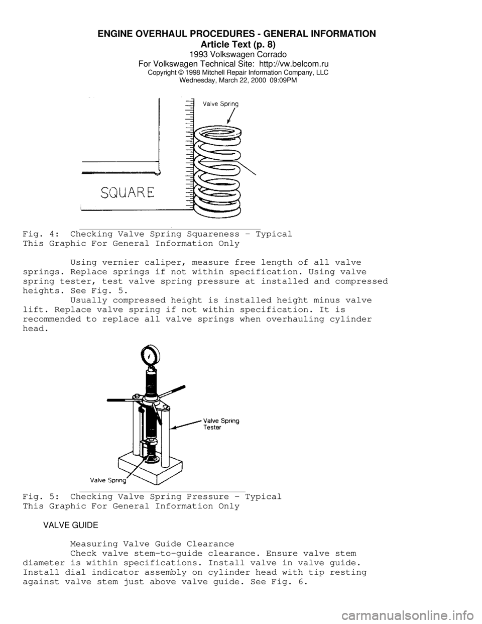
Wednesday, March 22, 2000 09:09PMFig. 4: Checking Valve Spring Squareness - Typical
This Graphic For General Information Only
Using vernier caliper, measure free length of all valve
springs. Replace springs if not within specification. Using valve
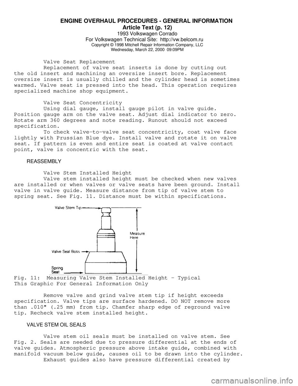
spring tester, test valve spring pressure at installed and compressed
heights. See Fig. 5.
Usually compressed height is installed height minus valve
lift. Replace valve spring if not within specification. It is
recommended to replace all valve springs when overhauling cylinder
head.Fig. 5: Checking Valve Spring Pressure - Typical
This Graphic For General Information Only
VALVE GUIDE
Measuring Valve Guide Clearance
Check valve stem-to-guide clearance. Ensure valve stem
diameter is within specifications. Install valve in valve guide.
Install dial indicator assembly on cylinder head with tip resting
against valve stem just above valve guide. See Fig. 6.
Page 541 of 920

ENGINE OVERHAUL PROCEDURES - GENERAL INFORMATION
Article Text (p. 12)
1993 Volkswagen Corrado
For Volkswagen Technical Site: http://vw.belcom.ru
Copyright © 1998 Mitchell Repair Information Company, LLC
Wednesday, March 22, 2000 09:09PM
Valve Seat Replacement
Replacement of valve seat inserts is done by cutting out
the old insert and machining an oversize insert bore. Replacement
oversize insert is usually chilled and the cylinder head is sometimes
warmed. Valve seat is pressed into the head. This operation requires
specialized machine shop equipment.
Valve Seat Concentricity
Using dial gauge, install gauge pilot in valve guide.
Position gauge arm on the valve seat. Adjust dial indicator to zero.
Rotate arm 360 degrees and note reading. Runout should not exceed
specification.
To check valve-to-valve seat concentricity, coat valve face
lightly with Prussian Blue dye. Install valve and rotate it on valve
seat. If pattern is even and entire seat is coated at valve contact
point, valve is concentric with the seat.
REASSEMBLY
Valve Stem Installed Height
Valve stem installed height must be checked when new valves
are installed or when valves or valve seats have been ground. Install
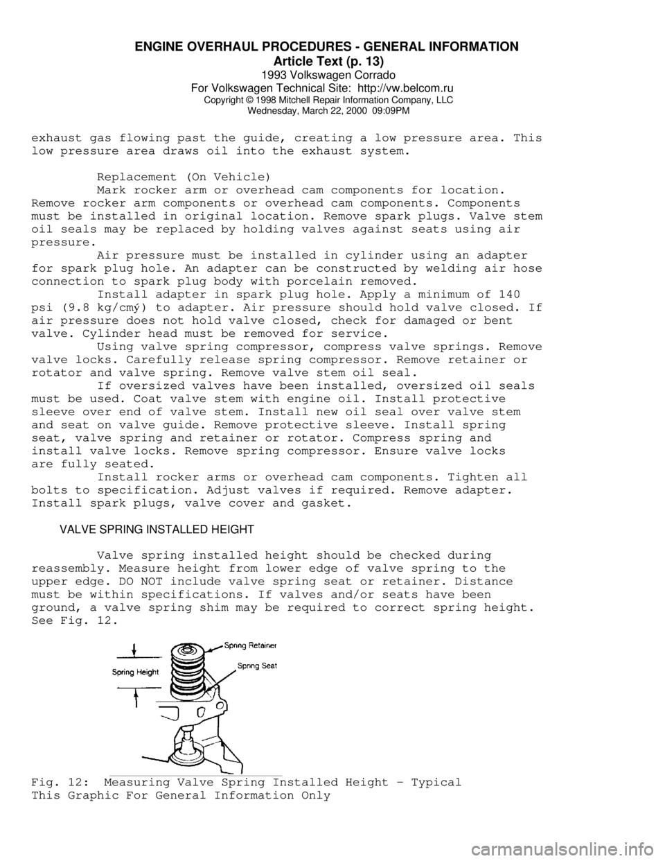
valve in valve guide. Measure distance from tip of valve stem to
spring seat. See Fig. 11. Distance must be within specifications.Fig. 11: Measuring Valve Stem Installed Height - Typical
This Graphic For General Information Only
Remove valve and grind valve stem tip if height exceeds
specification. Valve tips are surface hardened. DO NOT remove more
than .010" (.25 mm) from tip. Chamfer sharp edge of reground valve
tip. Recheck valve stem installed height.
VALVE STEM OIL SEALS
Valve stem oil seals must be installed on valve stem. See
Fig. 2. Seals are needed due to pressure differential at the ends of
valve guides. Atmospheric pressure above intake guide, combined with
manifold vacuum below guide, causes oil to be drawn into the cylinder.
Exhaust guides also have pressure differential created by
Page 542 of 920

ENGINE OVERHAUL PROCEDURES - GENERAL INFORMATION
Article Text (p. 13)
1993 Volkswagen Corrado
For Volkswagen Technical Site: http://vw.belcom.ru
Copyright © 1998 Mitchell Repair Information Company, LLC
Wednesday, March 22, 2000 09:09PM
exhaust gas flowing past the guide, creating a low pressure area. This
low pressure area draws oil into the exhaust system.
Replacement (On Vehicle)
Mark rocker arm or overhead cam components for location.
Remove rocker arm components or overhead cam components. Components
must be installed in original location. Remove spark plugs. Valve stem
oil seals may be replaced by holding valves against seats using air
pressure.
Air pressure must be installed in cylinder using an adapter
for spark plug hole. An adapter can be constructed by welding air hose
connection to spark plug body with porcelain removed.
Install adapter in spark plug hole. Apply a minimum of 140
psi (9.8 kg/cmý) to adapter. Air pressure should hold valve closed. If
air pressure does not hold valve closed, check for damaged or bent
valve. Cylinder head must be removed for service.
Using valve spring compressor, compress valve springs. Remove
valve locks. Carefully release spring compressor. Remove retainer or
rotator and valve spring. Remove valve stem oil seal.
If oversized valves have been installed, oversized oil seals
must be used. Coat valve stem with engine oil. Install protective
sleeve over end of valve stem. Install new oil seal over valve stem
and seat on valve guide. Remove protective sleeve. Install spring
seat, valve spring and retainer or rotator. Compress spring and
install valve locks. Remove spring compressor. Ensure valve locks
are fully seated.
Install rocker arms or overhead cam components. Tighten all
bolts to specification. Adjust valves if required. Remove adapter.
Install spark plugs, valve cover and gasket.
VALVE SPRING INSTALLED HEIGHT
Valve spring installed height should be checked during
reassembly. Measure height from lower edge of valve spring to the
upper edge. DO NOT include valve spring seat or retainer. Distance
must be within specifications. If valves and/or seats have been
ground, a valve spring shim may be required to correct spring height.
See Fig. 12.Fig. 12: Measuring Valve Spring Installed Height - Typical
This Graphic For General Information Only
Page 555 of 920

ENGINE OVERHAUL PROCEDURES - GENERAL INFORMATION
Article Text (p. 26)
1993 Volkswagen Corrado
For Volkswagen Technical Site: http://vw.belcom.ru
Copyright © 1998 Mitchell Repair Information Company, LLC
Wednesday, March 22, 2000 09:10PM
CYLINDER BORE INSPECTION
Inspect the bore for scuffing or roughness. Cylinder bore
is dimensionally checked for out-of-round and taper using dial bore
gauge. For determining out-of-round, measure cylinder parallel and
perpendicular to the block centerline. Difference in the 2 readings
is the bore out-of-round. Cylinder bore must be checked at top, middle
and bottom of piston travel area.
Bore taper is obtained by measuring bore at the top and
bottom. If wear has exceeded allowable limits, block must be honed
or bored to next available oversize piston dimension.
CYLINDER HONING
Cylinder must be properly honed to allow new piston rings to
properly seat. Cross-hatching at correct angle and depth is critical
to lubrication of cylinder walls and pistons.
A flexible drive hone and power drill are commonly used.
Drive hone must be lubricated during operation. Mix equal parts of
kerosene and SAE 20w engine oil for lubrication.
Apply lubrication to cylinder wall. Operate cylinder hone
from top to bottom of cylinder using even strokes to produce 45 degree
cross-hatch pattern on the cylinder wall. DO NOT allow cylinder hone
to extend below cylinder during operation.
Recheck bore dimension after final honing. Wash cylinder
wall with hot soapy water to remove abrasive particles. Blow dry with
compressed air. Coat cleaned cylinder walls with lubricating oil.
DECK WARPAGE
Check deck for damage or warped head sealing surface. Place
a straightedge across gasket surface of the deck. Using feeler gauge,
measure clearance at center of straightedge. Measure across width and
length of cylinder block at several points.
If warpage exceeds specifications, deck must be resurfaced.
If warpage exceeds manufacturer's maximum tolerance for material
removal, replace block.
DECK HEIGHT
Distance from the crankshaft centerline to the block
deck is termed the deck height. Measure and record front and rear main
journals of crankshaft. To compute this distance, install crankshaft
and retain with center main bearing and cap only. Measure distance
from the crankshaft journal to the block deck, parallel to the
cylinder centerline.
Add one half of the main bearing journal diameter to distance
from crankshaft journal to block deck. This dimension should be
checked at front and rear of cylinder block. Both readings should be
the same.
If difference exceeds specifications, cylinder block must be
repaired or replaced. Deck height and warpage should be corrected at
Page 608 of 920

HOW TO USE SYSTEM WIRING DIAGRAMS
Article Text (p. 5)
1993 Volkswagen Corrado
For Volkswagen Technical Site: http://vw.belcom.ru
Copyright © 1998 Mitchell Repair Information Company, LLC
Wednesday, March 22, 2000 09:11PM
Body Control Module .......................... Body Control Computer
Anti-Theft System
Daytime Running Lights
Engine Performance
Headlight Systems
Warning Systems
Boost Control Solenoid .......................... Engine Performance
Boost Sensor .................................... Engine Performance
Brake Fluid Level Switch .................. Analog Instrument Panels
Brake On/Off (BOO) Switch ................... Cruise Control Systems
Engine Performance
Shift Interlock Systems
Buzzer Module ...................................... Warning Systems
Camshaft Position (CMP) Sensor .................. Engine Performance
Central Control Module ........................... Anti-Theft System
Clockspring ............................... Air Bag Restraint System
Cruise Control Systems
Steering Column Switches
Clutch Pedal Position Switch .............................. Starters
Clutch Start Switch ....................................... Starters
Combination Meter ......................... Analog Instrument Panels
Constant Control Relay Module (CCRM) ............ Engine Performance
Electric Cooling Fans
Convenience Center .............................. Power Distribution
Illumination/Interior Lights
Convertible Top Motor ........................ Power Convertible Top
Convertible Top Switch ....................... Power Convertible Top
Crankshaft Position (CKP) Sensor ................ Engine Performance
Cruise Control Module ....................... Cruise Control Systems
Cruise Control Switch ....................... Cruise Control Systems
Condenser Fan Relay(s) ....................... Electric Cooling Fans
Data Link Connector (DLC) ....................... Engine Performance
Daytime Running Lights Module ............... Daytime Running Lights
Exterior Lights
Defogger Relay ................................ Rear Window Defogger
Diagnostic Energy Reserve Module (DERM) ... Air Bag Restraint System
Discriminating Sensor (Air Bag) ........... Air Bag Restraint System
Distributor ..................................... Engine Performance
Door Lock Actuators ............................... Power Door Locks
Remote Keyless Entry
Door Lock Relay(s) ................................ Power Door Locks
Electrochromic Mirror ................................ Power Mirrors
Electronic Level Control (ELC)
Height Sensor .............................. Electronic Suspension
Electronic Level Control (ELC) Module ........ Electronic Suspension
Engine Coolant Temperature (ECT)
Sending Unit ............................ Analog Instrument Panels
Engine Coolant Temperature (ECT) Sensor ......... Engine Performance
Engine Control Module ........................... Engine Performance
Generators & Regulators
Starters
ETACS ECU .......................................... Warning Systems