1993 FORD MONDEO steering
[x] Cancel search: steeringPage 73 of 279
31Where the vehicle is fitted with manual
transmission, disconnect the driveshafts from
the transmission as follows, referring to
Chapter 8 for further details when required:
(a) Unscrew the nuts securing the right-hand
driveshaft support bearing, and withdraw
the heat shield.
(b) Pull the right-hand driveshaft out of the
transmission; be prepared to catch any
spilt oil.
(c) Secure the driveshaft clear of the
engine/transmission - remember that the
unit is to be lowered out of the vehicle -
and ensure that the inner joint is not
turned through more than 18°.
(d) Prise the left-hand driveshaft out of the
transmission - again, be prepared for oil
spillage. Secure the driveshaft clear of the
engine/transmission, and ensure that its
inner joint is not turned through more than
18°.
32Where the vehicle is fitted with automatic
transmission, proceed as follows, referring to
Chapter 7, Part B and to Chapter 8 for further
details when required:
(a) Unscrew its centre bolt, then unbolt the
engine/transmission rear mounting
bracket from the transmission.
(b) Disconnect the fluid cooler pipe from the
rear of the transmission, and secure it
clear of the unit.
(c) Prise the left-hand driveshaft out of the
transmission; be prepared to catch any
spilt oil.
(d) Secure the driveshaft clear of the
engine/transmission - remember that the
unit is to be lowered out of the vehicle -
and ensure that the inner joint is not
turned through more than 18°.
(e) Unscrew the nuts securing the right-hand
driveshaft support bearing, and withdraw
the heat shield.
(f) Pull the right-hand driveshaft out of the
transmission - again, be prepared for oil
spillage. Secure the driveshaft clear of the
engine/transmission, and ensure that its
inner joint is not turned through more than
18°.
(g) Disconnect the fluid cooler pipe from the
front of the transmission, and secure it
clear of the unit.
33The engine/transmission unit should now
be hanging on the right- and left-hand
mountings only, with all components which
connect it to the rest of the vehicle
disconnected or removed and secured well
clear of the unit. Make a final check that this is
the case, then ensure that the body is
securely supported, high enough to permit the
withdrawal of the engine/transmission unit
from underneath; allow for the height of the
engine dolly, if used.
34Take the weight of the engine/
transmission unit, using the lifting eyes
provided on the cylinder head. Unscrew the
six nuts securing the right-hand mounting
bracket, then the three nuts securing the left-
hand bracket. Warning: Do not put any part of
your body under the vehicle, or
under the engine/transmission
unit, when they are supported only by a
hoist or other lifting equipment.
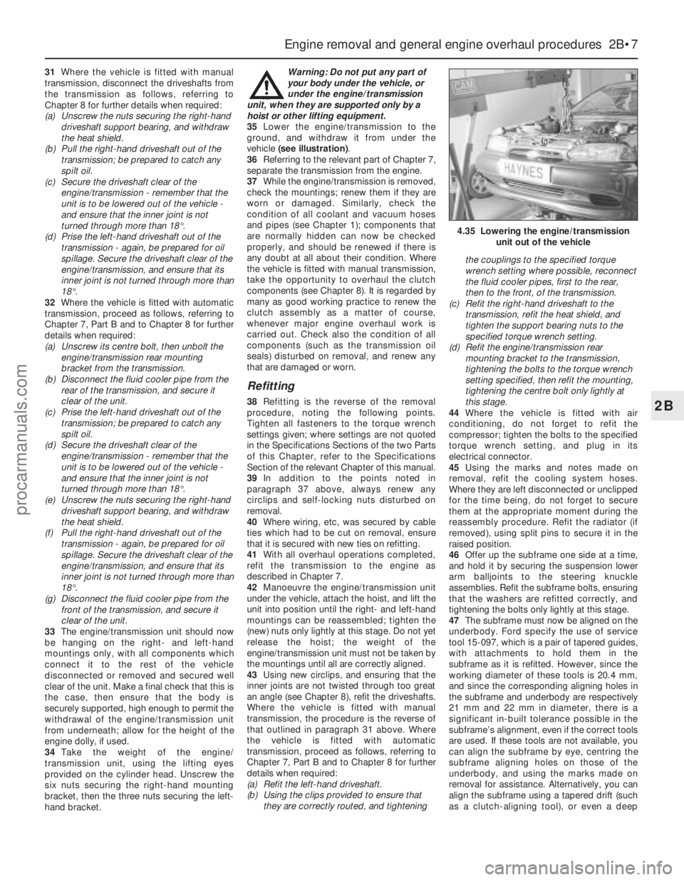
35Lower the engine/transmission to the
ground, and withdraw it from under the
vehicle (see illustration).
36Referring to the relevant part of Chapter 7,
separate the transmission from the engine.
37While the engine/transmission is removed,
check the mountings; renew them if they are
worn or damaged. Similarly, check the
condition of all coolant and vacuum hoses
and pipes (see Chapter 1); components that
are normally hidden can now be checked
properly, and should be renewed if there is
any doubt at all about their condition. Where
the vehicle is fitted with manual transmission,
take the opportunity to overhaul the clutch
components (see Chapter 8). It is regarded by
many as good working practice to renew the
clutch assembly as a matter of course,
whenever major engine overhaul work is
carried out. Check also the condition of all
components (such as the transmission oil
seals) disturbed on removal, and renew any
that are damaged or worn.
Refitting
38Refitting is the reverse of the removal
procedure, noting the following points.
Tighten all fasteners to the torque wrench
settings given; where settings are not quoted
in the Specifications Sections of the two Parts
of this Chapter, refer to the Specifications
Section of the relevant Chapter of this manual.
39In addition to the points noted in
paragraph 37 above, always renew any
circlips and self-locking nuts disturbed on
removal.
40Where wiring, etc, was secured by cable
ties which had to be cut on removal, ensure
that it is secured with new ties on refitting.
41With all overhaul operations completed,
refit the transmission to the engine as
described in Chapter 7.
42Manoeuvre the engine/transmission unit
under the vehicle, attach the hoist, and lift the
unit into position until the right- and left-hand
mountings can be reassembled; tighten the
(new) nuts only lightly at this stage. Do not yet
release the hoist; the weight of the
engine/transmission unit must not be taken by
the mountings until all are correctly aligned.
43Using new circlips, and ensuring that the
inner joints are not twisted through too great
an angle (see Chapter 8), refit the driveshafts.
Where the vehicle is fitted with manual
transmission, the procedure is the reverse of
that outlined in paragraph 31 above. Where
the vehicle is fitted with automatic
transmission, proceed as follows, referring to
Chapter 7, Part B and to Chapter 8 for further
details when required:
(a) Refit the left-hand driveshaft.
(b) Using the clips provided to ensure that
they are correctly routed, and tighteningthe couplings to the specified torque
wrench setting where possible, reconnect
the fluid cooler pipes, first to the rear,
then to the front, of the transmission.
(c) Refit the right-hand driveshaft to the
transmission, refit the heat shield, and
tighten the support bearing nuts to the
specified torque wrench setting.
(d) Refit the engine/transmission rear
mounting bracket to the transmission,
tightening the bolts to the torque wrench
setting specified, then refit the mounting,
tightening the centre bolt only lightly at
this stage.
44Where the vehicle is fitted with air
conditioning, do not forget to refit the
compressor; tighten the bolts to the specified
torque wrench setting, and plug in its
electrical connector.
45Using the marks and notes made on
removal, refit the cooling system hoses.
Where they are left disconnected or unclipped
for the time being, do not forget to secure
them at the appropriate moment during the
reassembly procedure. Refit the radiator (if
removed), using split pins to secure it in the
raised position.
46Offer up the subframe one side at a time,
and hold it by securing the suspension lower
arm balljoints to the steering knuckle
assemblies. Refit the subframe bolts, ensuring
that the washers are refitted correctly, and
tightening the bolts only lightly at this stage.
47The subframe must now be aligned on the
underbody. Ford specify the use of service
tool 15-097, which is a pair of tapered guides,
with attachments to hold them in the
subframe as it is refitted. However, since the
working diameter of these tools is 20.4 mm,
and since the corresponding aligning holes in
the subframe and underbody are respectively
21 mm and 22 mm in diameter, there is a
significant in-built tolerance possible in the
subframe’s alignment, even if the correct tools
are used. If these tools are not available, you
can align the subframe by eye, centring the
subframe aligning holes on those of the
underbody, and using the marks made on
removal for assistance. Alternatively, you can
align the subframe using a tapered drift (such
as a clutch-aligning tool), or even a deep
Engine removal and general engine overhaul procedures 2B•7
2B
4.35 Lowering the engine/transmission
unit out of the vehicle
procarmanuals.com
Page 74 of 279
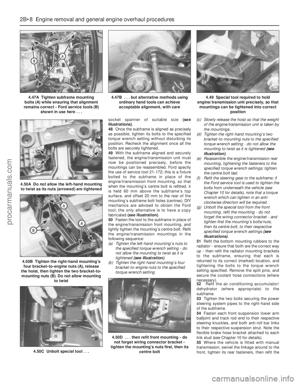
socket spanner of suitable size (see
illustrations).
48Once the subframe is aligned as precisely
as possible, tighten its bolts to the specified
torque wrench setting without disturbing its
position. Recheck the alignment once all the
bolts are securely tightened.
49With the subframe aligned and securely
fastened, the engine/transmission unit must
now be positioned precisely, before the
mountings can be reassembled. Ford specify
the use of service tool 21-172; this is a fixture
bolted to the subframe in place of the
engine/transmission front mounting, so that
when the mounting’s centre bolt is refitted, it
is held 60 mm above the subframe’s top
surface, and offset 20 mm to the rear of the
mounting’s subframe bolt holes (centres). DIY
mechanics are advised to obtain the Ford
tool; the only alternative is to have a copy
fabricated (see illustration).
50Fasten the tool to the subframe in place of
the engine/transmission front mounting, and
lightly tighten the mounting’s centre bolt. Refit
the engine/transmission mountings in the
following sequence:
(a) Tighten the left-hand mounting’s nuts to
the specified torque wrench setting - do
not allow the mounting to twist as it is
tightened (see illustration).
(b) Tighten the right-hand mounting’s four
bracket-to-engine nuts to the specified
torque wrench setting.(c) Slowly release the hoist so that the weight
of the engine/transmission unit is taken by
the mountings.
(d) Tighten the right-hand mounting’s two
bracket-to-mounting nuts to the specified
torque wrench setting - do not allow the
mounting to twist as it is tightened (see
illustration).
(e) Reassemble the engine/transmission rear
mounting, tightening the fasteners to the
specified torque wrench settings; tighten
the centre bolt last.
(f) Refit the steering gear to the subframe; if
the Ford service tool is used to tighten the
bolts from underneath the vehicle (see
Chapter 10 for details), note that a torque
wrench which can tighten in an anti-
clockwise direction will be required.
(g) Unbolt the special tool from the front
mounting, refit the mounting - do not
forget the wiring connector bracket - and
tighten first the mounting’s bolts/nuts,
then its centre bolt, to their respective
specified torque wrench settings (see
illustrations).
51Refit the bottom mounting rubbers to the
radiator - ensure that both are the correct way
up - then refit the radiator mounting brackets
to the subframe, ensuring that each is
returned to its correct (marked) location, and
tightening the bolts to the torque wrench
setting specified. Remove the split pins, and
secure the coolant hose connections (where
necessary).
52Refit the air conditioning accumulator/
dehydrator (where appropriate) to the
subframe.
53Tighten the two bolts securing the power
steering system pipes to the right-hand side
of the subframe.
54Fasten each front suspension lower arm
balljoint and track rod end to their respective
steering knuckles, and both anti-roll bar links
to their respective suspension strut. Note the
flexible brake hose bracket attached to each
link stud (see Chapter 10 for details).
55Where the vehicle is fitted with manual
transmission, swivel the linkage around to the
front, tighten its rear fasteners, then refit the
2B•8 Engine removal and general engine overhaul procedures
4.47A Tighten subframe mounting
bolts (A) while ensuring that alignment
remains correct - Ford service tools (B)
shown in use here . . .4.47B . . . but alternative methods using
ordinary hand tools can achieve
acceptable alignment, with care4.49 Special tool required to hold
engine/transmission unit precisely, so that
mountings can be tightened into correct
position
4.50B Tighten the right-hand mounting’s
four bracket-to-engine nuts (A), release
the hoist, then tighten the two bracket-to-
mounting nuts (B). Do not allow mounting
to twist
4.50A Do not allow the left-hand mounting
to twist as its nuts (arrowed) are tightened
4.50C Unbolt special tool . . .
4.50D . . . then refit front mounting - do
not forget wiring connector bracket -
tighten the mounting’s nuts first, then its
centre bolt
procarmanuals.com
Page 75 of 279
gear linkage heat shield. Reconnect the
gearchange linkage and transmission support
rods to the transmission, adjusting the linkage
using the marks made on removal (see
Chapter 7, Part A, for details).
56Re-install the remaining components and
fasteners in the reverse order of removal.
57Add coolant, engine oil and transmission
fluids as needed (see Chapter 1).
58Run the engine, and check for proper
operation and the absence of leaks. Shut off
the engine, and recheck the fluid levels.
59Remember that, since the front suspension
subframe and steering gear have been
disturbed, the wheel alignment and steering
angles must be checked fully and carefully as
soon as possible, with any necessary
adjustments being made. This operation is best
carried out by an experienced mechanic, using
proper checking equipment; the vehicle should
therefore be taken to a Ford dealer or similarly-
qualified person for attention.
1It is much easier to dismantle and work on
the engine if it is mounted on a portable engine
stand. These stands can often be hired from a
tool hire shop. Before the engine is mounted
on a stand, the flywheel/driveplate should be
removed (Part A of this Chapter, Section 21)
so that the stand bolts can be tightened into
the end of the cylinder block/crankcase.
2If a stand is not available, it is possible to
dismantle the engine with it mounted on
blocks, on a sturdy workbench or on the floor.
Be extra-careful not to tip or drop the engine
when working without a stand.
3If you are going to obtain a reconditioned
engine, all external components must be
removed first, to be transferred to the
replacement engine (just as they will if you are
doing a complete engine overhaul yourself).
Note:When removing the external
components from the engine, pay close
attention to details that may be helpful or
important during refitting. Note the fitted
position of gaskets, seals, spacers, pins,
washers, bolts and other small items.These
external components include the following:
(a) Alternator and brackets (Chapter 5).
(b) HT leads and spark plugs (Chapter 1).
(c) Thermostat and housing (Chapter 3).
(d) Dipstick tube.
(e) Fuel injection system components
(Chapter 4).
(f) All electrical switches and sensors - refer
to the appropriate Chapter.
(g) Inlet and exhaust manifolds (Part A of this
Chapter).
(h) Oil filter (Chapter 1).
(i) Engine/transmission mounting brackets
(Part A of this Chapter, Section 22).
(j) Flywheel/driveplate (Part A of this
Chapter, Section 21).
4If you are obtaining a “short” engine (whichconsists of the engine cylinder
block/crankcase, crankshaft, pistons and
connecting rods all assembled), then the
cylinder head, sump, oil pump, and timing belt
will have to be removed also.
5If you are planning a complete overhaul, the
engine can be dismantled and the internal
components removed in the following order.
(a) Inlet and exhaust manifolds (Part A of this
Chapter).
(b) Timing belt, toothed pulleys and
tensioner, and timing belt inner cover
(Part A of this Chapter).
(c) Cylinder head (Part A of this Chapter,
Section 14).
(d) Flywheel/driveplate (Part A of this
Chapter, Section 21).
(e) Sump (Part A of this Chapter, Section 15).
(f) Oil pump (Part A of this Chapter, Sec-
tion 16).
(g) Piston/connecting rod assemblies
(Section 9).
(h) Crankshaft (Section 10).
6Before beginning the dismantling andoverhaul procedures, make sure that you have
all of the correct tools necessary. Refer to the
introductory pages at the beginning of this
manual for further information.
Note:New and reconditioned cylinder heads
are available from the manufacturers, and
from engine overhaul specialists. Due to the
fact that some specialist tools are required for
the dismantling and inspection procedures,
and new components may not be readily
available (refer to Section 1 of this Part), it may
be more practical and economical for the
home mechanic to purchase a reconditioned
head, rather than to dismantle, inspect and
recondition the original head.
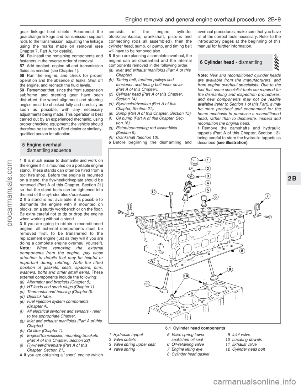
1Remove the camshafts and hydraulic
tappets (Part A of this Chapter, Section 13),
being careful to store the hydraulic tappets as
described (see illustration).
6 Cylinder head - dismantling
5 Engine overhaul-
dismantling sequence
Engine removal and general engine overhaul procedures 2B•9
2B
6.1 Cylinder head components
1 Hydraulic tappet
2 Valve collets
3 Valve spring upper seat
4 Valve spring5 Valve spring lower
seat/stem oil seal
6 Oil-retaining valve
7 Engine lifting eye
8 Cylinder head gasket9 Inlet valve
10 Locating dowels
11 Exhaust valve
12 Cylinder head bolt
procarmanuals.com
Page 94 of 279
Warning: Do not disconnect any
of the refrigerant hoses.
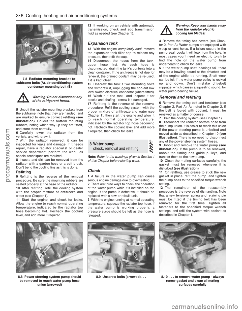
5Unbolt the radiator mounting brackets from
the subframe; note that they are handed, and
are marked to ensure correct refitting (see
illustration). Collect the bottom mounting
rubbers, noting which way up they are fitted,
and store them carefully.
6Carefully lower the radiator from the
vehicle, and withdraw it.
7With the radiator removed, it can be
inspected for leaks and damage. If it needs
repair, have a radiator specialist or dealer
service department perform the work, as
special techniques are required.
8Insects and dirt can be removed from the
radiator with a garden hose or a soft brush.
Don’t bend the cooling fins as this is done.
Refitting
9Refitting is the reverse of the removal
procedure. Be sure the mounting rubbers are
seated properly at the base of the radiator.
10After refitting, refill the cooling system
with the proper mixture of antifreeze and
water (see Chapter 1).
11Start the engine, and check for leaks.
Allow the engine to reach normal operating
temperature, indicated by the radiator top
hose becoming hot. Recheck the coolant
level, and add more if required.12If working on an vehicle with automatic
transmission, check and add transmission
fluid as needed (see Chapter 1).
Expansion tank
13With the engine completely cool, remove
the expansion tank filler cap to release any
pressure, then refit the cap.
14Disconnect the hoses from the tank,
upper hose first. As each hose is
disconnected, drain the tank’s contents into a
clean container. If the antifreeze is not due for
renewal, the drained coolant may be re-used,
if it is kept clean.
15Unscrew the tank’s two mounting bolts
and withdraw it, unplugging the coolant low
level switch electrical connector (where fitted).
16Wash out the tank, and inspect it for
cracks and chafing - renew it if damaged.
17Refitting is the reverse of the removal
procedure. Refill the cooling system with the
proper mixture of antifreeze and water (see
Chapter 1), then start the engine and allow it
to reach normal operating temperature,
indicated by the radiator top hose becoming
hot. Recheck the coolant level and add more
if required, then check for leaks.
Note:Refer to the warnings given in Section 1
of this Chapter before starting work.
Check
1A failure in the water pump can cause
serious engine damage due to overheating.
2There are three ways to check the operation
of the water pump while it’s installed on the
engine. If the pump is defective, it should be
replaced with a new or rebuilt unit.
3With the engine running at normal operating
temperature, squeeze the radiator top hose. If
the water pump is working properly, a
pressure surge should be felt as the hose is
released. Warning: Keep your hands away
from the radiator electric
cooling fan blades!
4Remove the timing belt covers (see Chap-
ter 2, Part A). Water pumps are equipped with
weep or vent holes. If a failure occurs in the
pump seal, coolant will leak from the hole. In
most cases you’ll need an electric torch to
find the hole on the water pump from
underneath to check for leaks.
5If the water pump shaft bearings fail, there
may be a howling sound at the drivebelt end
of the engine while it’s running. Shaft wear
can be felt if the water pump pulley is rocked
up and down. Don’t mistake drivebelt
slippage, which causes a squealing sound, for
water pump bearing failure.
Removal and refitting
6Remove the timing belt and tensioner (see
Chapter 2, Part A). As noted in Chapter 2, if
the belt is fouled with coolant, it must be
renewed as a matter of course.
7Drain the cooling system (see Chapter 1).
8Disconnect the radiator bottom hose from
the pump union. It is easier to reach this union
if the power steering pump is unbolted and
moved aside as described in Chapter 10 (see
illustration). There is no need to disconnect
any of the power steering system hoses.
9Unbolt and remove the water pump (see
illustration). If the pump is to be renewed,
unbolt the timing belt guide pulleys, and
transfer them to the new pump.
10Clean the mating surfaces carefully; the
gasket must be renewed whenever it is
disturbed (see illustration).
11On refitting, use grease to stick the new
gasket in place, refit the pump, and tighten
the pump bolts to the specified torque wrench
setting.
12The remainder of the reassembly
procedure is the reverse of dismantling. Note
that a new tensioner spring and retaining pin
must be fitted if the timing belt has been
removed for the first time. Tighten all
fasteners to the specified torque wrench
settings, and refill the system with coolant as
described in Chapter 1.
8 Water pump -
check, removal and refitting
3•6 Cooling, heating and air conditioning systems
7.5 Radiator mounting bracket-to-
subframe bolts (A), air conditioning system
condenser mounting bolt (B)
8.8 Power steering system pump should
be removed to reach water pump hose
union (arrowed)8.9 Unscrew bolts (arrowed) . . .8.10 . . . to remove water pump - always
renew gasket and clean all mating
surfaces carefully
procarmanuals.com
Page 115 of 279
5Undo the sensor’s retaining screw and
withdraw the sensor. The sensor’s bracket
cannot be unbolted from the cylinder
block/crankcase unless the transmission and
flywheel/driveplate have been removed (see
Chapter 2).
6Refitting is the reverse of the removal
procedure.
General information
The charging system includes the
alternator, an internal voltage regulator, a no-
charge (or “ignition”) warning light, the
battery, and the wiring between all the
components. The charging system supplies
electrical power for the ignition system, the
lights, the radio, etc. The alternator is driven
by the auxiliary drivebelt at the front (right-
hand end) of the engine.
The purpose of the voltage regulator is to
limit the alternator’s voltage to a preset value.
This prevents power surges, circuit overloads,
etc., during peak voltage output.
The charging system doesn’t ordinarily
require periodic maintenance. However, the
drivebelt, battery and wires and connections
should be inspected at the intervals outlined
in Chapter 1.
The dashboard warning light should come
on when the ignition key is turned to positions
“II” or “III”, then should go off immediately the
engine starts. If it remains on, or if it comes on
while the engine is running, there is a
malfunction in the charging system (see
Section 11). If the light does not come on
when the ignition key is turned, and the bulb is
sound (see Chapter 12), there is a fault in the
alternator.
Precautions
Be very careful when making electrical
circuit connections to a vehicle equipped with
an alternator, and note the following:
(a) When reconnecting wires to the alternator
from the battery, be sure to note the
polarity.
(b) Before using arc-welding equipment to
repair any part of the vehicle, disconnect
the wires from the alternator and the
battery terminals.
(c) Never start the engine with a battery
charger connected.
(d) Always disconnect both battery leads
before using a battery charger.
(e) The alternator is driven by an engine
drivebelt which could cause serious injury
if your hand, hair or clothes become
entangled in it with the engine running.
(f) Because the alternator is connected
directly to the battery, it could arc or
cause a fire if overloaded or shorted-out.
(g) Wrap a plastic bag over the alternator,
and secure it with rubber bands, beforesteam-cleaning or pressure-washing the
engine.
(h) Never disconnect the alternator terminals
while the engine is running.
1If a malfunction occurs in the charging
circuit, don’t automatically assume that the
alternator is causing the problem. First check
the following items:
(a) Check the tension and condition of the
auxiliary drivebelt - renew it if it is worn or
deteriorated (see Chapter 1).
(b) Ensure the alternator mounting bolts and
nuts are tight.
(c) Inspect the alternator wiring harness and
the electrical connections at the
alternator; they must be in good
condition, and tight.
(d) Check the large main fuses in the engine
compartment (see Chapter 12). If any is
blown, determine the cause, repair the
circuit and renew the fuse (the vehicle
won’t start and/or the accessories won’t
work if the fuse is blown).
(e) Start the engine and check the alternator
for abnormal noises - for example, a
shrieking or squealing sound may indicate
a badly-worn bearing or brush.
(f) Make sure that the battery is fully-charged
- one bad cell in a battery can cause
overcharging by the alternator.
(g) Disconnect the battery leads (negative
first, then positive). Inspect the battery
posts and the lead clamps for corrosion.
Clean them thoroughly if necessary (see
Section 3 and Chapter 1). Reconnect the
lead to the negative terminal.
(h) With the ignition and all accessories
switched off, insert a test light between
the battery negative post and the
disconnected negative lead clamp:
(1) If the test light does not come on, re-
attach the clamp and proceed to the next
step.
(2) If the test light comes on, there is a short
in the electrical system of the vehicle. The
short must be repaired before the
charging system can be checked.
(3) To find the short, disconnect the
alternator wiring harness:
(a) If the light goes out, the alternator is
at fault.
(b) If the light stays on, remove each fuse
until it goes out - this will tell you
which component is short-circuited.
2Using a voltmeter, check the battery
voltage with the engine off. It should be
approximately 12 volts.
3Start the engine and check the battery
voltage again. Increase engine speed until the
voltmeter reading remains steady; it should
now be approximately 13.5 to 14.6 volts.
4Switch on as many electrical accessories
(eg the headlights, heated rear window andheater blower) as possible, and check that the
alternator maintains the regulated voltage at
around 13 to 14 volts. The voltage may drop
and then come back up; it may also be
necessary to increase engine speed slightly,
even if the charging system is working
properly.
5If the voltage reading is greater than the
specified charging voltage, renew the voltage
regulator (see Section 13).
6If the voltmeter reading is less than that
specified, the fault may be due to worn
brushes, weak brush springs, a faulty voltage
regulator, a faulty diode, a severed phase
winding, or worn or damaged slip rings. The
brushes and slip rings may be checked (see
Section 13), but if the fault persists, the
alternator should be renewed or taken to an
auto-electrician for testing and repair.
1Disconnect the battery negative (earth) lead
- see Section 1.
2Remove the plenum chamber (see Chap-
ter 4).
3Unscrew the nuts to disconnect the wiring
from the alternator (see illustration). If
additional working clearance is required, undo
the right-hand of the three screws securing
the wiring “rail” to the rear of the inlet
manifold.
4Jack up and support the front right-hand
corner of the vehicle. Remove the auxiliary
drivebelt and the engine oil filter - place a wad
of rag to soak up the spilled oil (see Chap-
ter 1). Rather than refit a used filter, you are
advised to drain the engine oil, and then to fit
a new filter and refill the engine with clean oil
on reassembly. Where an engine oil cooler is
fitted, it may prove necessary to remove this
as well, to provide the clearance necessary to
remove the alternator (see Chapter 2, Part A).
5Unscrew the two bolts securing the power
steering system pipes to the right-hand side
of the front suspension subframe. With the
front wheels in the straight-ahead position,
disconnect the right-hand track rod end from
the steering knuckle (see Chapter 10).
6Remove the mounting bolts and nuts (one
12 Alternator-
removal and refitting
11 Charging system- testing
10 Charging system - general
information and precautions
Engine electrical systems 5•5
5
12.3 Disconnecting alternator wiring
procarmanuals.com
Page 123 of 279
5Support the caliper in one hand, and
prevent the hydraulic hose from turning with
the other hand. Unscrew the caliper from the
hose, making sure that the hose is not twisted
unduly or strained. Once the caliper is
detached, plug the open hydraulic unions in
the caliper and hose, to keep out dust and
dirt.
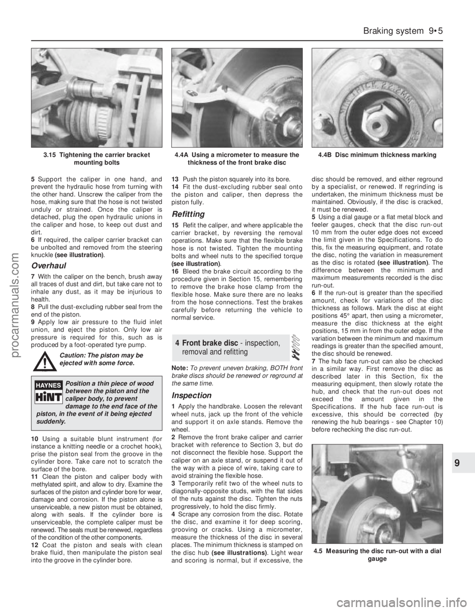
6If required, the caliper carrier bracket can
be unbolted and removed from the steering
knuckle (see illustration).
Overhaul
7With the caliper on the bench, brush away
all traces of dust and dirt, but take care not to
inhale any dust, as it may be injurious to
health.
8Pull the dust-excluding rubber seal from the
end of the piston.
9Apply low air pressure to the fluid inlet
union, and eject the piston. Only low air
pressure is required for this, such as is
produced by a foot-operated tyre pump.
Caution: The piston may be
ejected with some force.
10Using a suitable blunt instrument (for
instance a knitting needle or a crochet hook),
prise the piston seal from the groove in the
cylinder bore. Take care not to scratch the
surface of the bore.
11Clean the piston and caliper body with
methylated spirit, and allow to dry. Examine the
surfaces of the piston and cylinder bore for wear,
damage and corrosion. If the piston alone is
unserviceable, a new piston must be obtained,
along with seals. If the cylinder bore is
unserviceable, the complete caliper must be
renewed. The seals must be renewed, regardless
of the condition of the other components.
12Coat the piston and seals with clean
brake fluid, then manipulate the piston seal
into the groove in the cylinder bore.13Push the piston squarely into its bore.
14Fit the dust-excluding rubber seal onto
the piston and caliper, then depress the
piston fully.
Refitting
15Refit the caliper, and where applicable the
carrier bracket, by reversing the removal
operations. Make sure that the flexible brake
hose is not twisted. Tighten the mounting
bolts and wheel nuts to the specified torque
(see illustration).
16Bleed the brake circuit according to the
procedure given in Section 15, remembering
to remove the brake hose clamp from the
flexible hose. Make sure there are no leaks
from the hose connections. Test the brakes
carefully before returning the vehicle to
normal service.
Note:To prevent uneven braking, BOTH front
brake discs should be renewed or reground at
the same time.
Inspection
1Apply the handbrake. Loosen the relevant
wheel nuts, jack up the front of the vehicle
and support it on axle stands. Remove the
wheel.
2Remove the front brake caliper and carrier
bracket with reference to Section 3, but do
not disconnect the flexible hose. Support the
caliper on an axle stand, or suspend it out of
the way with a piece of wire, taking care to
avoid straining the flexible hose.
3Temporarily refit two of the wheel nuts to
diagonally-opposite studs, with the flat sides
of the nuts against the disc. Tighten the nuts
progressively, to hold the disc firmly.
4Scrape any corrosion from the disc. Rotate
the disc, and examine it for deep scoring,
grooving or cracks. Using a micrometer,
measure the thickness of the disc in several
places. The minimum thickness is stamped on
the disc hub (see illustrations). Light wear
and scoring is normal, but if excessive, thedisc should be removed, and either reground
by a specialist, or renewed. If regrinding is
undertaken, the minimum thickness must be
maintained. Obviously, if the disc is cracked,
it must be renewed.
5Using a dial gauge or a flat metal block and
feeler gauges, check that the disc run-out
10 mm from the outer edge does not exceed
the limit given in the Specifications. To do
this, fix the measuring equipment, and rotate
the disc, noting the variation in measurement
as the disc is rotated (see illustration). The
difference between the minimum and
maximum measurements recorded is the disc
run-out.
6If the run-out is greater than the specified
amount, check for variations of the disc
thickness as follows. Mark the disc at eight
positions 45° apart, then using a micrometer,
measure the disc thickness at the eight
positions, 15 mm in from the outer edge. If the
variation between the minimum and maximum
readings is greater than the specified amount,
the disc should be renewed.
7The hub face run-out can also be checked
in a similar way. First remove the disc as
described later in this Section, fix the
measuring equipment, then slowly rotate the
hub, and check that the run-out does not
exceed the amount given in the
Specifications. If the hub face run-out is
excessive, this should be corrected (by
renewing the hub bearings - see Chapter 10)
before rechecking the disc run-out.
4 Front brake disc - inspection,
removal and refitting
Braking system 9•5
9
4.5 Measuring the disc run-out with a dial
gauge
3.15 Tightening the carrier bracket
mounting bolts4.4A Using a micrometer to measure the
thickness of the front brake disc4.4B Disc minimum thickness marking
Position a thin piece of wood
between the piston and the
caliper body, to prevent
damage to the end face of the
piston, in the event of it being ejected
suddenly.
procarmanuals.com
Page 130 of 279
Repeat the procedure at the other end of the
pipe, then release the pipe by pulling out the
clips attaching it to the body (see
illustrations). Where the union nuts are
exposed to the full force of the weather, they
can sometimes be quite tight. If an open-
ended spanner is used, burring of the flats on
the nuts is not uncommon, and for this
reason, it is preferable to use a split ring
(brake) spanner, which will engage all the
flats. If such a spanner is not available, self-
locking grips may be used as a last resort;
these may well damage the nuts, but if the
pipe is to be renewed, this does not matter.
7To further minimise the loss of fluid when
disconnecting a flexible brake line from a rigid
pipe, clamp the hose as near as possible to
the pipe to be detached, using a brake hose
clamp or a pair of self-locking grips with
protected jaws.
8To remove a flexible hose, first clean the
ends of the hose and the surrounding area,
then unscrew the union nuts from the hose
ends. Recover the spring clip, and withdraw
the hose from the serrated mounting in the
support bracket. Where applicable, unscrew
the hose from the caliper.
9Brake pipes supplied with flared ends and
union nuts can be obtained individually or in
sets from Ford dealers or accessory shops.
The pipe is then bent to shape, using the old
pipe as a guide, and is ready for fitting. Be
careful not to kink or crimp the pipe when
bending it; ideally, a proper pipe-bending tool
should be used.
Refitting
10Refitting of the pipes and hoses is a
reversal of removal. Make sure that all brake
pipes are securely supported in their clips,
and ensure that the hoses are not kinked.
Check also that the hoses are clear of all
suspension components and underbody
fittings, and will remain clear during
movement of the suspension and steering.
11On completion, bleed the brake hydraulic
system as described in Section 15.
Warning: Brake fluid is
poisonous. Take care to keep it
off bare skin, and in particular
not to get splashes in your eyes.
The fluid also attacks paintwork - wash off
spillages immediately with cold water.
1If the master cylinder has been
disconnected and reconnected, then the
complete system (both circuits) must be bled
of air. If a component of one circuit has been
disturbed, then only that particular circuit
need be bled.
2Bleeding should commence on one front
brake, followed by the diagonally-opposite
rear brake. The remaining front brake should
then be bled, followed by its diagonally-
opposite rear brake.
3There are a variety of do-it-yourself “one-
man” brake bleeding kits available from motor
accessory shops, and it is recommended that
one of these kits be used wherever possible,
as they greatly simplify the brake bleeding
operation. Follow the kit manufacturer’s
instructions in conjunction with the following
procedure. If a pressure-bleeding kit is
obtained, then it will not be necessary to
depress the brake pedal in the following
procedure.
4During the bleeding operation, do not allow
the brake fluid level in the reservoir to drop
below the minimum mark. If the level is
allowed to fall so far that air is drawn in, the
whole procedure will have to be started again
from scratch. Only use new fluid for topping-
up, preferably from a freshly-opened
container. Never re-use fluid bled from the
system.
5Before starting, check that all rigid pipes
and flexible hoses are in good condition, and
that all hydraulic unions are tight. Take great
care not to allow hydraulic fluid to come into
contact with the vehicle paintwork, otherwise
the finish will be seriously damaged. Wash off
any spilt fluid immediately with cold water.
6If a brake bleeding kit is not being used,
gather together a clean jar, a length of plastic
or rubber tubing which is a tight fit over the
bleed screw, and a new can of the specified
brake fluid (see Chapter 1 Specifications). The
help of an assistant will also be required.
7Clean the area around the bleed screw on
the front brake unit to be bled (it is importantthat no dirt be allowed to enter the hydraulic
system), and remove the dust cap. Connect
one end of the tubing to the bleed screw, and
immerse the other end in the jar, which should
be filled with sufficient brake fluid to keep the
end of the tube submerged.
8Open the bleed screw by one or two turns,
and have the assistant depress the brake
pedal to the floor. Tighten the bleed screw at
the end of the downstroke, then have the
assistant release the pedal. Continue this
procedure until clean brake fluid, free from air
bubbles, can be seen flowing into the jar.
Finally tighten the bleed screw with the pedal
in the fully-depressed position.
9Remove the tube, and refit the dust cap.
Top-up the master cylinder reservoir if
necessary, then repeat the procedure on the
diagonally-opposite rear brake.
10Repeat the procedure on the remaining
circuit, starting with the front brake, and
followed by the diagonally-opposite rear
brake.
11Check the feel of the brake pedal - it
should be firm. If it is spongy, there is still
some air in the system, and the bleeding
procedure should be repeated.
12When bleeding is complete, top-up the
master cylinder reservoir and refit the cap.
Testing
1To test the operation of the servo unit,
depress the footbrake four or five times to
dissipate the vacuum, then start the engine
while keeping the footbrake depressed. As
the engine starts, there should be a noticeable
“give” in the brake pedal as vacuum builds
up. Allow the engine to run for at least two
minutes, and then switch it off. If the brake
pedal is now depressed again, it should be
possible to hear a hiss from the servo when
the pedal is depressed. After four or five
applications, no further hissing should be
heard, and the pedal should feel harder.
2Before assuming that a problem exists in
the servo unit itself, inspect the non-return
valve as described in the next Section.
Removal
3Refer to Section 11 and remove the master
cylinder.
4Disconnect the vacuum hose adaptor at the
servo unit by pulling it free from the rubber
grommet. If it is reluctant to move, prise it
free, using a screwdriver with its blade
inserted under the flange.
5Unscrew the four nuts securing the servo
unit to the mounting brackets on the bulkhead
in the engine compartment.
6On right-hand drive models, withdraw the
servo unit so that its studs are just clear of the
brackets. Have an assistant hold the brake
pedal depressed, then extract the spring clip
16 Vacuum servo unit -
testing, removal and refitting
15 Hydraulic system - bleeding
9•12 Braking system
14.6A Unscrewing a brake pipe union nut
using a split ring spanner
14.6B Pulling out a brake pipe mounting
clip
procarmanuals.com
Page 132 of 279
Note:If any part of the ABS hydraulic unit is
defective, it must be renewed as an assembly.
Apart from the relay box (Section 22),
individual spare parts are not available.
Removal
1Remove both pressure-control relief valves
as described in Section 19.
2Identify the location of the remaining brake
hydraulic pipes on the ABS hydraulic unit,
then unscrew the union nuts and pull out the
pipes. Carefully bend the pipes away from the
hydraulic unit, to allow the unit to be removed.
3Disconnect the multi-plugs from the
hydraulic unit. To disconnect the main 22-pin
multi-plug, push the locktab, then swivel the
multi-plug outwards and unhook it.
Right-hand drive models
4Have an assistant hold the brake pedal
depressed, then extract the spring clip and
remove the clevis pin securing the servo unit
pushrod to the pedal cross-link arm.
5Remove the vacuum servo unit from the
engine compartment.
Left-hand drive models
6Unscrew the nut securing the pedal
trunnion to the servo unit pushrod inside the
passenger compartment. The nut is located
near the top of the pedal, and is accessible
through an access hole. For improved access,
remove the lower facia panel first.
7Remove the vacuum servo unit, together
with the pushrod, from the engine
compartment. Take care not to damage the
rubber grommet in the bulkhead.
All models
8Unscrew the pump mounting nut.
9Raise the left-hand side of the ABS
hydraulic unit, then swivel the unit out of the
right-hand mounting. Take care not to lose the
bracket studs and insulator ring.
Refitting
10Locate the insulator ring on the pump
end, and fit the stud cap to the insulator ring.
11Lower the ABS hydraulic unit into
position, right-hand end first.
12Fit the right-hand bracket studs onto the
insulators.
13Lower the left-hand end of the ABS
hydraulic unit onto the bracket, then fit and
tighten the pump mounting nut.
Left-hand drive models
14Locate the vacuum servo unit and
pushrod on the bulkhead bracket, taking care
not to damage the rubber grommet.
15Insert the pushrod in the pedal trunnion,
and tighten the nut.
16Refit the lower facia panel if it was
removed.
Right-hand drive models
17Locate the vacuum servo unit and
pushrod on the bulkhead bracket.
18Refit the clevis pin and spring clip
securing the servo unit pushrod to the pedal
cross-link arm.
All models
19Reconnect the multi-plugs to the
hydraulic unit.
20Reconnect the brake pipes to the
hydraulic unit, and tighten the union nuts.
21Refit both pressure-control relief valves,
with reference to Section 20.
Testing
1Checking of the sensors is done before
removal, connecting a voltmeter to the
disconnected sensor multi-plug. Using an
analogue (moving coil) meter is not practical,
since the meter does not respond quickly
enough. A digital meter having an AC facility
may be used to check that the sensor is
operating correctly. To do this, raise the
relevant wheel then disconnect the wiring to
the ABS sensor and connect the meter to it.
Spin the wheel and check that the output
voltage is between 1.5 and 2.0 volts,
depending on how fast the wheel is spun.
Alternatively, an oscilloscope may be used to
check the output of the sensor - an alternating
current will be traced on the screen, of
magnitude depending on the speed of the
rotating wheel.
2If the sensor output is low or zero, renew
the sensor.
Removal
Front wheel sensor
3Apply the handbrake, jack up the front of
the vehicle and support it on axle stands.
Remove the relevant wheel.
4Unscrew the sensor mounting bolt located
on the steering knuckle, and withdraw the
sensor (see illustrations).
5Remove the sensor wiring loom from thesupport brackets on the front suspension
strut and wheel arch.
6Prise out the stud clips, and remove the
Torx screws and screw clips holding the wheel
arch liner in position. Withdraw the liner.
7Disconnect the multi-plug, and withdraw
the sensor and wiring loom.
Rear wheel sensor
8Chock the front wheels, and engage 1st
gear (or “P”). Jack up the rear of the vehicle
and support it on axle stands. Remove the
relevant wheel.
9Unscrew the sensor mounting bolt, located
on the brake backplate (drum brakes) or rear
suspension knuckle (disc brakes), and
withdraw the sensor.
10On disc brake models, prise out the stud
clips, and remove the Torx screws and screw
clips holding the wheel arch liner in position.
Withdraw the liner.
11Disconnect the sensor wiring loom from
the supports on the rear suspension strut (or
knuckle) and wheel arch.
12Working inside the vehicle, lift the rear
seat cushion, then disconnect the multi-plug
for the sensor wiring loom (see illustration).
13Withdraw the sensor and wiring loom
through the rubber grommet in the rear floor.
Refitting
Front and rear wheel sensors
14Refitting is a reversal of the removal
procedure.
Removal
1Disconnect the battery negative (earth) lead
(Chapter 5, Section 1).
2Detach the vacuum hose from the inlet
manifold connection, pressing in the collar to
disengage the tabs, then withdrawing the
collar slowly.
3To improve access, free the heater hose
from its retaining clips, and position it clear of
the relay box.
4Disconect the wiring connector(s) from the
relay box and, where necessary, the speed
sender unit.
22 ABS relay box -
removal and refitting
21 ABS wheel sensor -
testing, removal and refitting
20 ABS hydraulic unit -
removal and refitting
9•14 Braking system
21.4 Unscrew the mounting bolt and
remove the ABS sensor21.12 Rear ABS sensor wiring multi-plug
located beneath the rear seat
procarmanuals.com