1993 FORD MONDEO fuse
[x] Cancel search: fusePage 205 of 279
compartment, but on Estate models, it is on
the right-hand side.
Some models are fitted with a headlight
levelling system, which is controlled by a knob
on the facia. On position “0”, the headlights
are in their base position, and on position “5”,
the headlights are in their maximum inclined
angle.
It should be noted that, when portions of
the electrical system are serviced, the cable
should be disconnected from the battery
negative terminal, to prevent electrical shorts
and fires.
Caution: When disconnecting the
battery for work described in the
following Sections, refer to
Chapter 5, Section 1.
Note:Refer to the precautions given in
“Safety first!” and in Section 1 of this Chapter
before starting work. The following tests relate
to testing of the main electrical circuits, and
should not be used to test delicate electronic
circuits (such as engine management systems,
anti-lock braking systems, etc), particularly
where an electronic control module is used.
Also refer to the precautions given in Chapter
5, Section 1.
General
1A typical electrical circuit consists of an
electrical component, any switches, relays,
motors, fuses, fusible links or circuit breakers
related to that component, and the wiring and
connectors which link the component to both
the battery and the chassis. To help to
pinpoint a problem in an electrical circuit,
wiring diagrams are included at the end of this
manual.
2Before attempting to diagnose an electrical
fault, first study the appropriate wiring
diagram, to obtain a complete understanding
of the components included in the particular
circuit concerned. The possible sources of a
fault can be narrowed down by noting if other
components related to the circuit are
operating properly. If several components or
circuits fail at one time, the problem is likely to
be related to a shared fuse or earth
connection.
3Electrical problems usually stem from
simple causes, such as loose or corroded
connections, a faulty earth connection, a
blown fuse, a melted fusible link, or a faulty
relay (refer to Section 3 for details of testing
relays). Visually inspect the condition of all
fuses, wires and connections in a problem
circuit before testing the components. Use
the wiring diagrams to determine which
terminal connections will need to be checked
in order to pinpoint the trouble-spot.
4The basic tools required for electrical fault-
finding include a circuit tester or voltmeter (a
12-volt bulb with a set of test leads can alsobe used for certain tests); an ohmmeter (to
measure resistance and check for continuity);
a battery and set of test leads; and a jumper
wire, preferably with a circuit breaker or fuse
incorporated, which can be used to bypass
suspect wires or electrical components.
Before attempting to locate a problem with
test instruments, use the wiring diagram to
determine where to make the connections.
5To find the source of an intermittent wiring
fault (usually due to a poor or dirty
connection, or damaged wiring insulation), a
“wiggle” test can be performed on the wiring.
This involves wiggling the wiring by hand to
see if the fault occurs as the wiring is moved.
It should be possible to narrow down the
source of the fault to a particular section of
wiring. This method of testing can be used in
conjunction with any of the tests described in
the following sub-Sections.
6Apart from problems due to poor
connections, two basic types of fault can
occur in an electrical circuit - open-circuit, or
short-circuit.
7Open-circuit faults are caused by a break
somewhere in the circuit, which prevents
current from flowing. An open-circuit fault will
prevent a component from working.
8Short-circuit faults are caused by a “short”
somewhere in the circuit, which allows the
current flowing in the circuit to “escape” along
an alternative route, usually to earth. Short-
circuit faults are normally caused by a
breakdown in wiring insulation, which allows a
feed wire to touch either another wire, or an
earthed component such as the bodyshell. A
short-circuit fault will normally cause the
relevant circuit fuse to blow.
Finding an open-circuit
9To check for an open-circuit, connect one
lead of a circuit tester or the negative lead of a
voltmeter either to the battery negative
terminal or to a known good earth.
10Connect the other lead to a connector in
the circuit being tested, preferably nearest to
the battery or fuse. At this point, battery
voltage should be present, unless the lead
from the battery or the fuse itself is faulty
(bearing in mind that some circuits are live
only when the ignition switch is moved to a
particular position).
11Switch on the circuit, then connect the
tester lead to the connector nearest the circuit
switch on the component side.
12If voltage is present (indicated either by
the tester bulb lighting or a voltmeter reading,
as applicable), this means that the section of
the circuit between the relevant connector
and the switch is problem-free.
13Continue to check the remainder of the
circuit in the same fashion.
14When a point is reached at which no
voltage is present, the problem must lie
between that point and the previous test point
with voltage. Most problems can be traced to
a broken, corroded or loose connection.
Finding a short-circuit
15To check for a short-circuit, first
disconnect the load(s) from the circuit (loads
are the components which draw current from
a circuit, such as bulbs, motors, heating
elements, etc).
16Remove the relevant fuse from the circuit,
and connect a circuit tester or voltmeter to the
fuse connections.
17Switch on the circuit, bearing in mind that
some circuits are live only when the ignition
switch is moved to a particular position.
18If voltage is present (indicated either by
the tester bulb lighting or a voltmeter reading,
as applicable), this means that there is a
short-circuit.
19If no voltage is present during this test,
but the fuse still blows with the load(s)
reconnected, this indicates an internal fault in
the load(s).
Finding an earth fault
20The battery negative terminal is
connected to “earth” - the metal of the
engine/transmission unit and the vehicle body
- and many systems are wired so that they
only receive a positive feed, the current
returning via the metal of the car body. This
means that the component mounting and the
body form part of that circuit. Loose or
corroded mountings can therefore cause a
range of electrical faults, ranging from total
failure of a circuit, to a puzzling partial failure.
In particular, lights may shine dimly (especially
when another circuit sharing the same earth
point is in operation), motors (eg wiper motors
or the radiator cooling fan motor) may run
slowly, and the operation of one circuit may
have an apparently-unrelated effect on
another. Note that on many vehicles, earth
straps are used between certain components,
such as the engine/transmission and the
body, usually where there is no metal-to-
metal contact between components, due to
flexible rubber mountings, etc.
21To check whether a component is
properly earthed, disconnect the battery (refer
to Chapter 5, Section 1) and connect one lead
of an ohmmeter to a known good earth point.
Connect the other lead to the wire or earth
connection being tested. The resistance
reading should be zero; if not, check the
connection as follows.
22If an earth connection is thought to be
faulty, dismantle the connection, and clean
both the bodyshell and the wire terminal (or
the component earth connection mating
surface) back to bare metal. Be careful to
remove all traces of dirt and corrosion, then
use a knife to trim away any paint, so that a
clean metal-to-metal joint is made. On
reassembly, tighten the joint fasteners
securely; if a wire terminal is being refitted,
use serrated washers between the terminal
and the bodyshell, to ensure a clean and
secure connection. When the connection is
2 Electrical fault finding -
general information
12•4 Body electrical system
procarmanuals.com
Page 206 of 279
remade, prevent the onset of corrosion in the
future by applying a coat of petroleum jelly or
silicone-based grease, or by spraying on (at
regular intervals) a proprietary ignition sealer
such as Holts Damp Start, or a water-
dispersant lubricant such as Holts Wet Start.
Note:It is important to note that the ignition
switch and the appropriate electrical circuit
must always be switched off before any of the
fuses (or relays) are removed and renewed. In
the event of the fuse/relay unit having to be
removed, the battery earth lead must be
disconnected. When reconnecting the battery,
reference should be made to Chapter 5.
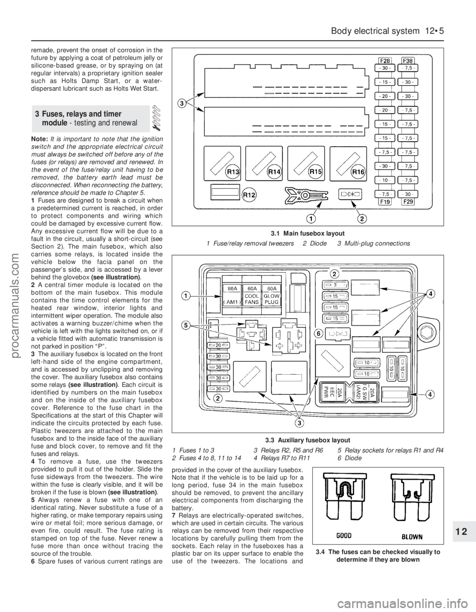
1Fuses are designed to break a circuit when
a predetermined current is reached, in order
to protect components and wiring which
could be damaged by excessive current flow.
Any excessive current flow will be due to a
fault in the circuit, usually a short-circuit (see
Section 2). The main fusebox, which also
carries some relays, is located inside the
vehicle below the facia panel on the
passenger’s side, and is accessed by a lever
behind the glovebox (see illustration).
2A central timer module is located on the
bottom of the main fusebox. This module
contains the time control elements for the
heated rear window, interior lights and
intermittent wiper operation. The module also
activates a warning buzzer/chime when the
vehicle is left with the lights switched on, or if
a vehicle fitted with automatic transmission is
not parked in position “P”.
3The auxiliary fusebox is located on the front
left-hand side of the engine compartment,
and is accessed by unclipping and removing
the cover. The auxiliary fusebox also contains
some relays (see illustration). Each circuit is
identified by numbers on the main fusebox
and on the inside of the auxiliary fusebox
cover. Reference to the fuse chart in the
Specifications at the start of this Chapter will
indicate the circuits protected by each fuse.
Plastic tweezers are attached to the main
fusebox and to the inside face of the auxiliary
fuse and block cover, to remove and fit the
fuses and relays.
4To remove a fuse, use the tweezers
provided to pull it out of the holder. Slide the
fuse sideways from the tweezers. The wire
within the fuse is clearly visible, and it will be
broken if the fuse is blown (see illustration).
5Always renew a fuse with one of an
identical rating. Never substitute a fuse of a
higher rating, or make temporary repairs using
wire or metal foil; more serious damage, or
even fire, could result. The fuse rating is
stamped on top of the fuse. Never renew a
fuse more than once without tracing the
source of the trouble.
6Spare fuses of various current ratings areprovided in the cover of the auxiliary fusebox.
Note that if the vehicle is to be laid up for a
long period, fuse 34 in the main fusebox
should be removed, to prevent the ancillary
electrical components from discharging the
battery.
7Relays are electrically-operated switches,
which are used in certain circuits. The various
relays can be removed from their respective
locations by carefully pulling them from the
sockets. Each relay in the fuseboxes has a
plastic bar on its upper surface to enable the
use of the tweezers. The locations and
3 Fuses, relays and timer
module- testing and renewal
Body electrical system 12•5
12
3.4 The fuses can be checked visually to
determine if they are blown
3.1 Main fusebox layout
1 Fuse/relay removal tweezers 2 Diode 3 Multi-plug connections
3.3 Auxiliary fusebox layout
1 Fuses 1 to 3 3 Relays R2, R5 and R6 5 Relay sockets for relays R1 and R4
2 Fuses 4 to 8, 11 to 14 4 Relays R7 to R11 6 Diode
procarmanuals.com
Page 207 of 279
functions of the various relays are given in the
Specifications (see illustration).
8If a component controlled by a relay
becomes inoperative and the relay is suspect,
listen to the relay as the circuit is operated. If
the relay is functioning, it should be possible
to hear it click as it is energized. If the relay
proves satisfactory, the fault lies with the
components or wiring of the system. If the
relay is not being energized, then either the
relay is not receiving a switching voltage, or
the relay itself is faulty. (Do not overlook the
relay socket terminals when tracing faults.)
Testing is by the substitution of a known good
unit, but be careful; while some relays are
identical in appearance and in operation,
others look similar, but perform different
functions.9The central timer module located on the
bottom of the main fusebox incorporates its
own self-diagnosis function. Note that
diagnosis cannot take place if the heated rear
window is defective.
10To activate the system, press the heated
rear window button while the ignition is being
switched on, then release the button. Operate
the light switch, washer pump switch and all
of the door switches one after the other, and
check that the buzzer confirms that the input
signals are correct.
11Now move the wiper lever to the
intermittent wipe position, and check the
output signals by operating the same
switches.
12The self-diagnosis function is turned off
by switching the ignition off and on again.
Removal
Ignition switch and lock barrel
1Disconnect the battery negative (earth) lead
(refer to Chapter 5, Section 1).
2Remove the rubber gaiters and locking
rings, then remove the securing screws and
take off the steering column upper and lower
shrouds.
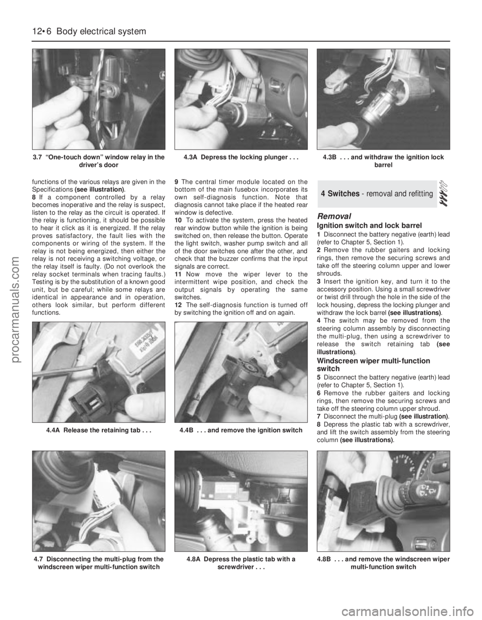
3Insert the ignition key, and turn it to the
accessory position. Using a small screwdriver
or twist drill through the hole in the side of the
lock housing, depress the locking plunger and
withdraw the lock barrel (see illustrations).
4The switch may be removed from the
steering column assembly by disconnecting
the multi-plug, then using a screwdriver to
release the switch retaining tab (see
illustrations).
Windscreen wiper multi-function
switch
5Disconnect the battery negative (earth) lead
(refer to Chapter 5, Section 1).
6Remove the rubber gaiters and locking
rings, then remove the securing screws and
take off the steering column upper shroud.
7Disconnect the multi-plug (see illustration).
8Depress the plastic tab with a screwdriver,
and lift the switch assembly from the steering
column (see illustrations).
4 Switches - removal and refitting
12•6 Body electrical system
3.7 “One-touch down” window relay in the
driver’s door4.3A Depress the locking plunger . . .4.3B . . . and withdraw the ignition lock
barrel
4.7 Disconnecting the multi-plug from the
windscreen wiper multi-function switch4.8A Depress the plastic tab with a
screwdriver . . .
4.4A Release the retaining tab . . .4.4B . . . and remove the ignition switch
4.8B . . . and remove the windscreen wiper
multi-function switch
procarmanuals.com
Page 213 of 279
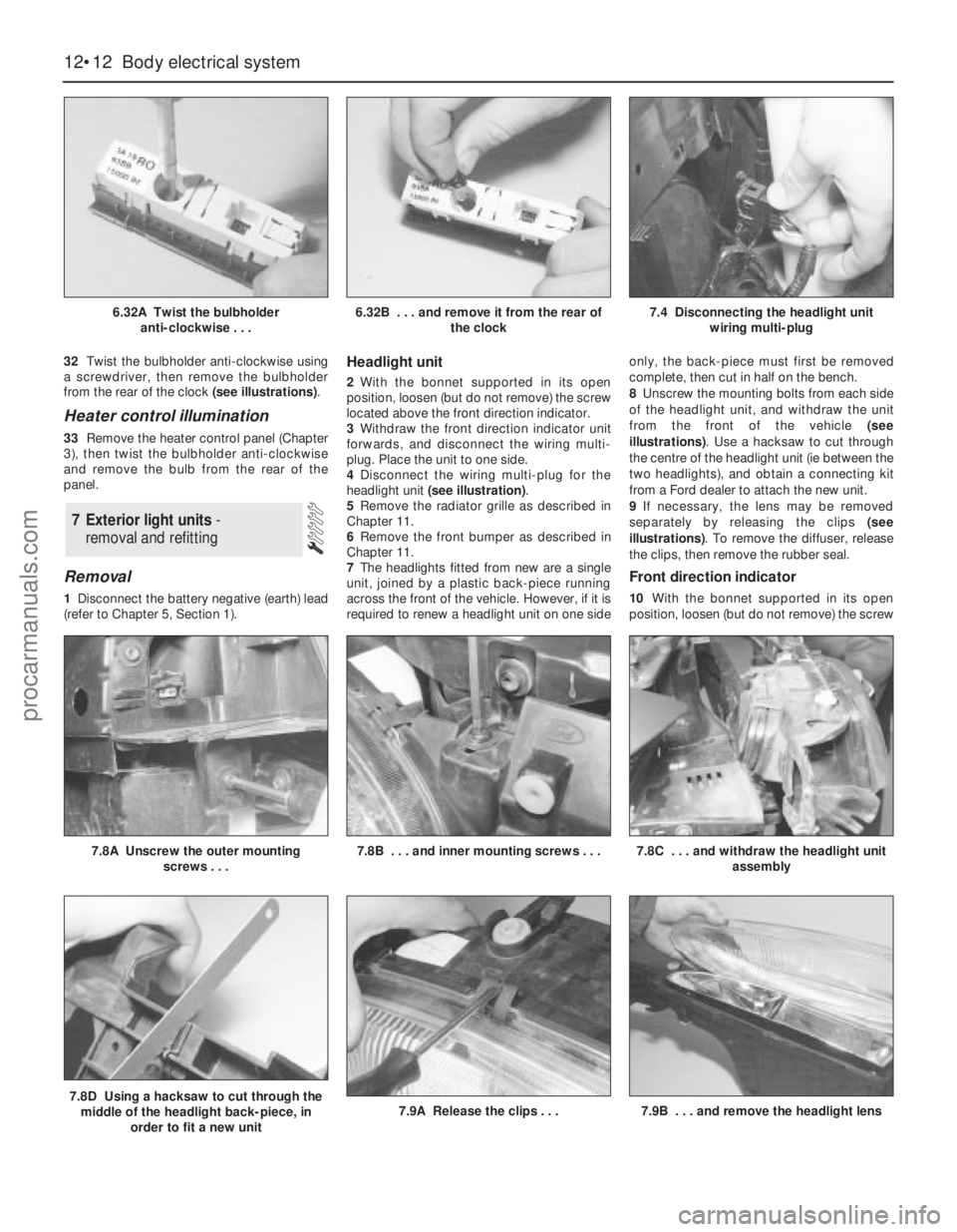
32Twist the bulbholder anti-clockwise using
a screwdriver, then remove the bulbholder
from the rear of the clock (see illustrations).
Heater control illumination
33Remove the heater control panel (Chapter
3), then twist the bulbholder anti-clockwise
and remove the bulb from the rear of the
panel.
Removal
1Disconnect the battery negative (earth) lead
(refer to Chapter 5, Section 1).
Headlight unit
2With the bonnet supported in its open
position, loosen (but do not remove) the screw
located above the front direction indicator.
3Withdraw the front direction indicator unit
forwards, and disconnect the wiring multi-
plug. Place the unit to one side.
4Disconnect the wiring multi-plug for the
headlight unit (see illustration).
5Remove the radiator grille as described in
Chapter 11.
6Remove the front bumper as described in
Chapter 11.
7The headlights fitted from new are a single
unit, joined by a plastic back-piece running
across the front of the vehicle. However, if it is
required to renew a headlight unit on one sideonly, the back-piece must first be removed
complete, then cut in half on the bench.
8Unscrew the mounting bolts from each side
of the headlight unit, and withdraw the unit
from the front of the vehicle (see
illustrations). Use a hacksaw to cut through
the centre of the headlight unit (ie between the
two headlights), and obtain a connecting kit
from a Ford dealer to attach the new unit.
9If necessary, the lens may be removed
separately by releasing the clips (see
illustrations). To remove the diffuser, release
the clips, then remove the rubber seal.
Front direction indicator
10With the bonnet supported in its open
position, loosen (but do not remove) the screw
7 Exterior light units -
removal and refitting
12•12 Body electrical system
6.32A Twist the bulbholder
anti-clockwise . . .6.32B . . . and remove it from the rear of
the clock7.4 Disconnecting the headlight unit
wiring multi-plug
7.8D Using a hacksaw to cut through the
middle of the headlight back-piece, in
order to fit a new unit7.9A Release the clips . . .7.9B . . . and remove the headlight lens
7.8A Unscrew the outer mounting
screws . . .7.8B . . . and inner mounting screws . . .7.8C . . . and withdraw the headlight unit
assembly
procarmanuals.com
Page 215 of 279
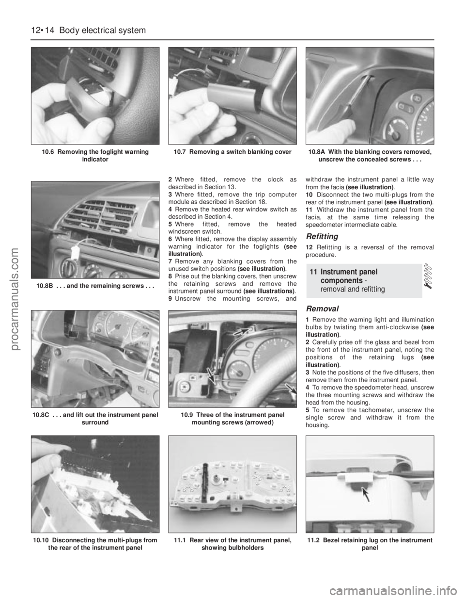
2Where fitted, remove the clock as
described in Section 13.
3Where fitted, remove the trip computer
module as described in Section 18.
4Remove the heated rear window switch as
described in Section 4.
5Where fitted, remove the heated
windscreen switch.
6Where fitted, remove the display assembly
warning indicator for the foglights (see
illustration).
7Remove any blanking covers from the
unused switch positions (see illustration).
8Prise out the blanking covers, then unscrew
the retaining screws and remove the
instrument panel surround (see illustrations).
9Unscrew the mounting screws, andwithdraw the instrument panel a little way
from the facia (see illustration).
10Disconnect the two multi-plugs from the
rear of the instrument panel (see illustration).
11Withdraw the instrument panel from the
facia, at the same time releasing the
speedometer intermediate cable.
Refitting
12Refitting is a reversal of the removal
procedure.
Removal
1Remove the warning light and illumination
bulbs by twisting them anti-clockwise (see
illustration).
2Carefully prise off the glass and bezel from
the front of the instrument panel, noting the
positions of the retaining lugs (see
illustration).
3Note the positions of the five diffusers, then
remove them from the instrument panel.
4To remove the speedometer head, unscrew
the three mounting screws and withdraw the
head from the housing.
5To remove the tachometer, unscrew the
single screw and withdraw it from the
housing.
11 Instrument panel
components-
removal and refitting
12•14 Body electrical system
10.6 Removing the foglight warning
indicator10.7 Removing a switch blanking cover10.8A With the blanking covers removed,
unscrew the concealed screws . . .
10.10 Disconnecting the multi-plugs from
the rear of the instrument panel11.1 Rear view of the instrument panel,
showing bulbholders11.2 Bezel retaining lug on the instrument
panel
10.8C . . . and lift out the instrument panel
surround10.9 Three of the instrument panel
mounting screws (arrowed)
10.8B . . . and the remaining screws . . .
procarmanuals.com
Page 263 of 279
REF•4
Whenever servicing, repair or overhaul work
is carried out on the car or its components, it
is necessary to observe the following
procedures and instructions. This will assist in
carrying out the operation efficiently and to a
professional standard of workmanship.
Joint mating faces and gaskets
When separating components at their
mating faces, never insert screwdrivers or
similar implements into the joint between the
faces in order to prise them apart. This can
cause severe damage which results in oil
leaks, coolant leaks, etc upon reassembly.
Separation is usually achieved by tapping
along the joint with a soft-faced hammer in
order to break the seal. However, note that
this method may not be suitable where
dowels are used for component location.
Where a gasket is used between the mating
faces of two components, ensure that it is
renewed on reassembly, and fit it dry unless
otherwise stated in the repair procedure.
Make sure that the mating faces are clean and
dry, with all traces of old gasket removed.
When cleaning a joint face, use a tool which is
not likely to score or damage the face, and
remove any burrs or nicks with an oilstone or
fine file.
Make sure that tapped holes are cleaned
with a pipe cleaner, and keep them free of
jointing compound, if this is being used,
unless specifically instructed otherwise.
Ensure that all orifices, channels or pipes
are clear, and blow through them, preferably
using compressed air.
Oil seals
Oil seals can be removed by levering them
out with a wide flat-bladed screwdriver or
similar implement. Alternatively, a number of
self-tapping screws may be screwed into the
seal, and these used as a purchase for pliers
or some similar device in order to pull the seal
free.
Whenever an oil seal is removed from its
working location, either individually or as part
of an assembly, it should be renewed.
The very fine sealing lip of the seal is easily
damaged, and will not seal if the surface it
contacts is not completely clean and free from
scratches, nicks or grooves.
Protect the lips of the seal from any surface
which may damage them in the course of
fitting. Use tape or a conical sleeve where
possible. Lubricate the seal lips with oil before
fitting and, on dual-lipped seals, fill the space
between the lips with grease.
Unless otherwise stated, oil seals must be
fitted with their sealing lips toward the
lubricant to be sealed.
Use a tubular drift or block of wood of the
appropriate size to install the seal and, if the
seal housing is shouldered, drive the seal
down to the shoulder. If the seal housing is
unshouldered, the seal should be fitted with
its face flush with the housing top face (unless
otherwise instructed).
Screw threads and fastenings
Seized nuts, bolts and screws are quite a
common occurrence where corrosion has set
in, and the use of penetrating oil or releasing
fluid will often overcome this problem if the
offending item is soaked for a while before
attempting to release it. The use of an impact
driver may also provide a means of releasing
such stubborn fastening devices, when used
in conjunction with the appropriate
screwdriver bit or socket. If none of these
methods works, it may be necessary to resort
to the careful application of heat, or the use of
a hacksaw or nut splitter device.
Studs are usually removed by locking two
nuts together on the threaded part, and then
using a spanner on the lower nut to unscrew
the stud. Studs or bolts which have broken off
below the surface of the component in which
they are mounted can sometimes be removed
using a proprietary stud extractor. Always
ensure that a blind tapped hole is completely
free from oil, grease, water or other fluid
before installing the bolt or stud. Failure to do
this could cause the housing to crack due to
the hydraulic action of the bolt or stud as it is
screwed in.
When tightening a castellated nut to accept
a split pin, tighten the nut to the specified
torque, where applicable, and then tighten
further to the next split pin hole. Never slacken
the nut to align the split pin hole, unless stated
in the repair procedure.
When checking or retightening a nut or bolt
to a specified torque setting, slacken the nut
or bolt by a quarter of a turn, and then
retighten to the specified setting. However,
this should not be attempted where angular
tightening has been used.
For some screw fastenings, notably cylinder
head bolts or nuts, torque wrench settings are
no longer specified for the latter stages of
tightening, “angle-tightening” being called up
instead. Typically, a fairly low torque wrench
setting will be applied to the bolts/nuts in
the correct sequence, followed by one or
more stages of tightening through specified
angles.
Locknuts, locktabs and washers
Any fastening which will rotate against a
component or housing in the course of
tightening should always have a washer
between it and the relevant component or
housing.
Spring or split washers should always be
renewed when they are used to lock a critical
component such as a big-end bearing
retaining bolt or nut. Locktabs which are
folded over to retain a nut or bolt should
always be renewed.
Self-locking nuts can be re-used in non-
critical areas, providing resistance can be felt
when the locking portion passes over the bolt
or stud thread. However, it should be noted
that self-locking stiffnuts tend to lose theireffectiveness after long periods of use, and in
such cases should be renewed as a matter of
course.
Split pins must always be replaced with
new ones of the correct size for the hole.
When thread-locking compound is found
on the threads of a fastener which is to be re-
used, it should be cleaned off with a wire
brush and solvent, and fresh compound
applied on reassembly.
Special tools
Some repair procedures in this manual
entail the use of special tools such as a press,
two or three-legged pullers, spring
compressors, etc. Wherever possible, suitable
readily-available alternatives to the
manufacturer’s special tools are described,
and are shown in use. Unless you are highly-
skilled and have a thorough understanding of
the procedures described, never attempt to
bypass the use of any special tool when the
procedure described specifies its use. Not
only is there a very great risk of personal
injury, but expensive damage could be
caused to the components involved.
Environmental considerations
When disposing of used engine oil, brake
fluid, antifreeze, etc, give due consideration to
any detrimental environmental effects. Do not,
for instance, pour any of the above liquids
down drains into the general sewage system,
or onto the ground to soak away. Many local
council refuse tips provide a facility for waste
oil disposal, as do some garages. If none of
these facilities are available, consult your local
Environmental Health Department for further
advice.
With the universal tightening-up of
legislation regarding the emission of
environmentally-harmful substances from
motor vehicles, most current vehicles have
tamperproof devices fitted to the main
adjustment points of the fuel system. These
devices are primarily designed to prevent
unqualified persons from adjusting the fuel/air
mixture, with the chance of a consequent
increase in toxic emissions. If such devices
are encountered during servicing or overhaul,
they should, wherever possible, be renewed
or refitted in accordance with the vehicle
manufacturer’s requirements or current
legislation.
Note: It is
antisocial and
illegal to dump
oil down the
drain. To find
the location of
your local oil
recycling
bank, call this
number free.
General Repair Procedures
procarmanuals.com
Page 266 of 279
REF•7
Engine fails to rotate when attempting to start
m mBattery terminal connections loose or corroded (Chapter 5).
m mBattery discharged or faulty (Chapter 5).
m mBroken, loose or disconnected wiring in the starting circuit
(Chapter 5).
m mDefective starter solenoid or switch (Chapter 5).
m mDefective starter motor (Chapter 5).
m mStarter pinion or flywheel ring gear teeth loose or broken (Chap-
ter 5).
m mEngine earth strap broken or disconnected (Chapter 5).
m mAutomatic transmission not in Park/Neutral position, or selector
lever position sensor faulty (Chapter 7, Part B).
Engine rotates but will not start
m mFuel tank empty.
m mBattery discharged (engine rotates slowly) (Chapter 5).
m mBattery terminal connections loose or corroded (Chapter 5).
m mIgnition components damp or damaged (Chapters 1 and 5).
m mBroken, loose or disconnected wiring in the ignition circuit
(Chapters 1 and 5).
m mWorn, faulty or incorrectly-gapped spark plugs (Chapter 1).
m mMajor mechanical failure (eg camshaft drive) (Chapter 2, Part A).
Engine difficult to start when cold
m
mBattery discharged (Chapter 5).
m mBattery terminal connections loose or corroded (Chapter 5).
m mWorn, faulty or incorrectly-gapped spark plugs (Chapter 1).
m mOther ignition system fault (Chapters 1 and 5).
m mEngine management system fault (Chapters 1, 4, 5 and 6)
m mLow cylinder compressions (Chapter 2, Part A).
Engine difficult to start when hot
m
mAir filter element dirty or clogged (Chapter 1).
m mEngine management system fault (Chapters 1, 4, 5 and 6)
m mLow cylinder compressions (Chapter 2, Part A).
m mFaulty hydraulic tappet(s) (Chapter 2, Part A).
Starter motor noisy or excessively-rough in
engagement
m mStarter pinion or flywheel ring gear teeth loose or broken (Chapter 5).
m mStarter motor mounting bolts loose or missing (Chapter 5).
m mStarter motor internal components worn or damaged (Chapter 5).
Engine starts but stops immediately
m
mLoose or faulty electrical connections in the ignition circuit
(Chapters 1 and 5).
m mEngine management system fault (Chapters 1, 4, 5 and 6)
m mVacuum leak at the inlet manifold (Chapters 1, 4 and 6).
Engine idles erratically
m
mIdle speed control valve faulty (Chapter 4).
m mEngine management system fault (Chapters 1, 4, 5 and 6)
m mAir filter element clogged (Chapter 1).
m mVacuum leak at the inlet manifold or associated hoses (Chap-
ters 1, 4 and 6).
m mWorn, faulty or incorrectly-gapped spark plugs (Chapter 1).
m mFaulty hydraulic tappet(s) (Chapter 2, Part A).
m mUneven or low cylinder compressions (Chapter 2, Part A).
m mCamshaft lobes worn (Chapter 2).
m mTiming belt incorrectly-tensioned (Chapter 2, Part A).
Engine misfires at idle speed
m
mWorn, faulty or incorrectly-gapped spark plugs (Chapter 1).
m mFaulty spark plug HT leads (Chapter 1).
m mIdle speed control valve faulty (Chapter 4).
m mIncorrect ignition timing (Chapters 5 and 6).
m mEngine management system fault (Chapters 1, 4, 5 and 6)
m mVacuum leak at the inlet manifold or associated hoses (Chap-
ters 1, 4 and 6).
m mFaulty hydraulic tappet(s) (Chapter 2, Part A).
m mUneven or low cylinder compressions (Chapter 2, Part A).
m mDisconnected, leaking or perished crankcase ventilation hoses
(Chapters 1 and 6).
Fault Finding
The vehicle owner who does his or her own maintenance according
to the recommended service schedules should not have to use this
section of the manual very often. Modern component reliability is such
that, provided those items subject to wear or deterioration are inspected
or renewed at the specified intervals, sudden failure is comparatively
rare. Faults do not usually just happen as a result of sudden failure, but
develop over a period of time. Major mechanical failures in particular are
usually preceded by characteristic symptoms over hundreds or even
thousands of miles. Those components which do occasionally fail
without warning are often small and easily carried in the vehicle.
With any fault-finding, the first step is to decide where to begin
investigations. Sometimes this is obvious, but on other occasions, a
little detective work will be necessary. The owner who makes half a
dozen haphazard adjustments or replacements may be successful in
curing a fault (or its symptoms), but will be none the wiser if the fault
recurs, and ultimately may have spent more time and money than was
necessary. A calm and logical approach will be found to be more
satisfactory in the long run. Always take into account any warning
signs or abnormalities that may have been noticed in the period
preceding the fault - power loss, high or low gauge readings, unusual
smells, etc - and remember that failure of components such as fuses
or spark plugs may only be pointers to some underlying fault.
The pages which follow provide an easy reference guide to the
more common problems which may occur during the operation of the
vehicle. These problems and their possible causes are grouped underheadings denoting various components or systems, such as Engine,
Cooling system, etc. The Chapter and/or Section which deals with the
problem is also shown in brackets. Whatever the fault, certain basic
principles apply. These are as follows:
Verify the fault. This is simply a matter of being sure that you know
what the symptoms are before starting work. This is particularly
important if you are investigating a fault for someone else, who may
not have described it very accurately.
Don’t overlook the obvious. For example, if the vehicle won’t start, is
there petrol in the tank? (Don’t take anyone else’s word on this
particular point, and don’t trust the fuel gauge either!) If an electrical
fault is indicated, look for loose or broken wires before digging out the
test gear.
Cure the disease, not the symptom. Substituting a flat battery with a
fully-charged one will get you off the hard shoulder, but if the underlying
cause is not attended to, the new battery will go the same way. Similarly,
changing oil-fouled spark plugs for a new set will get you moving again,
but remember that the reason for the fouling (if it wasn’t simply an
incorrect grade of plug) will have to be established and corrected.
Don’t take anything for granted. Particularly, don’t forget that a
“new” component may itself be defective (especially if it’s been
rattling around in the boot for months), and don’t leave components
out of a fault diagnosis sequence just because they are new or
recently fitted. When you do finally diagnose a difficult fault, you’ll
probably realise that all the evidence was there from the start.
1 Engine
Introduction
procarmanuals.com
Page 269 of 279
6 Automatic transmission
REF•10Fault Finding
Note:Due to the complexity of the automatic transmission and its
electronic control system, it is difficult for the home mechanic to
properly diagnose and service this unit. For problems other than the
following, the vehicle should be taken to a dealer service department
or automatic transmission specialist.
Fluid leakage
m mAutomatic transmission fluid is usually deep red in colour. Fluid
leaks should not be confused with engine oil, which can easily be
blown onto the transmission by airflow.
m mTo determine the source of a leak, first remove all built-up dirt and
grime from the transmission housing and surrounding areas, using
a degreasing agent, or by steam-cleaning. Drive the vehicle at low
speed, so airflow will not blow the leak far from its source. Raise
and support the vehicle, and determine where the leak is coming
from. The following are common areas of leakage:
(a) Housing joints (Chapters 1 and 7, Part B).
(b) Dipstick tube (Chapters 1 and 7, Part B).
(c) Transmission-to-fluid cooler pipes/unions (Chapters 3 and 7,
Part B).
(d) Speedometer drive pinion O-ring (Chapter 7, Part B).
(e) Differential side gear oil seals (Chapter 7, Part B).
Transmission fluid brown, or has burned smell
m mTransmission fluid level low, or fluid in need of renewal (Chapter 1).
Transmission will not downshift (kickdown) with
accelerator pedal fully depressed
m mLow transmission fluid level (Chapter 1).
m mIncorrect selector cable adjustment (Chapter 7, Part B).
m mEngine management system fault (Chapters 1, 4, 5 and 6).
General gear selection problems
m
mChapter 7, Part B, deals with checking and adjusting the selector
cable on automatic transmissions. The following are common
problems which may be caused by a poorly-adjusted cable:
(a) Engine starting in gears other than Park or Neutral.
(b) Indicator on gear selector lever pointing to a gear other than the
one actually being used.
(c) Vehicle moves when in Park or Neutral.
(d) Poor gear shift quality or erratic gear changes.
Refer to Chapter 7, Part B for the selector cable adjustment
procedure.
Engine will not start in any gear, or starts in gears
other than Park or Neutral
m mIncorrect selector lever position sensor adjustment (Chapter 7,
Part B).
m mIncorrect selector cable adjustment (Chapter 7, Part B).
Transmission slips, shifts roughly, is noisy, or has no
drive in forward or reverse gears
m mThere are many probable causes for the above problems, but the
home mechanic should be concerned with only one possibility -
fluid level. Before taking the vehicle to a dealer or transmission
specialist, check the fluid level and condition of the fluid as
described in Chapter 1. Correct the fluid level as necessary, or
change the fluid if needed. If the problem persists, professional
help will be necessary.
7 Driveshafts
Clicking or knocking noise on turns (at slow speed
on full-lock)
m mLack of constant velocity joint lubricant (Chapter 8).
m mWorn outer constant velocity joint (Chapter 8).
Vibration when accelerating or decelerating
m
mWorn inner constant velocity joint (Chapter 8).
m mBent or distorted driveshaft (Chapter 8).
8 Braking system
Note:Before assuming that a brake problem exists, make sure that the tyres are in good condition and correctly inflated, that the front wheel
alignment is correct, and that the vehicle is not loaded with weight in an unequal manner. Apart from checking the condition of all pipe and hose
connections, any faults occurring on the Anti-lock Braking System (ABS) should be referred to a Ford dealer for diagnosis - the same applies to the
components of the Traction Control System (TCS).
Vehicle pulls to one side under braking
m mWorn, defective, damaged or contaminated front or rear brake
pads/shoes on one side (Chapter 1).
m mSeized or partially-seized front or rear brake caliper/wheel cylinder
piston (Chapter 9).
m mA mixture of brake pad/shoe lining materials fitted between sides
(Chapter 1).
m mBrake caliper mounting bolts loose (Chapter 9).
m mRear brake backplate mounting bolts loose (Chapter 9).
m mWorn or damaged steering or suspension components (Chap-
ter 10).
Noise (grinding or high-pitched squeal) when brakes
applied
m mBrake pad or shoe friction lining material worn down to metal
backing (Chapter 1).
m mExcessive corrosion of brake disc or drum (may be apparent after
the vehicle has been standing for some time) (Chapter 1).
m mForeign object (stone chipping, etc) trapped between brake disc
and splash shield (Chapter 1).
Excessive brake pedal travel
m mInoperative rear brake self-adjust mechanism (Chapter 9).
m mFaulty master cylinder (Chapter 9).
m mAir in hydraulic system (Chapter 9).
procarmanuals.com