1993 FORD MONDEO seat adjustment
[x] Cancel search: seat adjustmentPage 75 of 279
gear linkage heat shield. Reconnect the
gearchange linkage and transmission support
rods to the transmission, adjusting the linkage
using the marks made on removal (see
Chapter 7, Part A, for details).
56Re-install the remaining components and
fasteners in the reverse order of removal.
57Add coolant, engine oil and transmission
fluids as needed (see Chapter 1).
58Run the engine, and check for proper
operation and the absence of leaks. Shut off
the engine, and recheck the fluid levels.
59Remember that, since the front suspension
subframe and steering gear have been
disturbed, the wheel alignment and steering
angles must be checked fully and carefully as
soon as possible, with any necessary
adjustments being made. This operation is best
carried out by an experienced mechanic, using
proper checking equipment; the vehicle should
therefore be taken to a Ford dealer or similarly-
qualified person for attention.
1It is much easier to dismantle and work on
the engine if it is mounted on a portable engine
stand. These stands can often be hired from a
tool hire shop. Before the engine is mounted
on a stand, the flywheel/driveplate should be
removed (Part A of this Chapter, Section 21)
so that the stand bolts can be tightened into
the end of the cylinder block/crankcase.
2If a stand is not available, it is possible to
dismantle the engine with it mounted on
blocks, on a sturdy workbench or on the floor.
Be extra-careful not to tip or drop the engine
when working without a stand.
3If you are going to obtain a reconditioned
engine, all external components must be
removed first, to be transferred to the
replacement engine (just as they will if you are
doing a complete engine overhaul yourself).
Note:When removing the external
components from the engine, pay close
attention to details that may be helpful or
important during refitting. Note the fitted
position of gaskets, seals, spacers, pins,
washers, bolts and other small items.These
external components include the following:
(a) Alternator and brackets (Chapter 5).
(b) HT leads and spark plugs (Chapter 1).
(c) Thermostat and housing (Chapter 3).
(d) Dipstick tube.
(e) Fuel injection system components
(Chapter 4).
(f) All electrical switches and sensors - refer
to the appropriate Chapter.
(g) Inlet and exhaust manifolds (Part A of this
Chapter).
(h) Oil filter (Chapter 1).
(i) Engine/transmission mounting brackets
(Part A of this Chapter, Section 22).
(j) Flywheel/driveplate (Part A of this
Chapter, Section 21).
4If you are obtaining a “short” engine (whichconsists of the engine cylinder
block/crankcase, crankshaft, pistons and
connecting rods all assembled), then the
cylinder head, sump, oil pump, and timing belt
will have to be removed also.
5If you are planning a complete overhaul, the
engine can be dismantled and the internal
components removed in the following order.
(a) Inlet and exhaust manifolds (Part A of this
Chapter).
(b) Timing belt, toothed pulleys and
tensioner, and timing belt inner cover
(Part A of this Chapter).
(c) Cylinder head (Part A of this Chapter,
Section 14).
(d) Flywheel/driveplate (Part A of this
Chapter, Section 21).
(e) Sump (Part A of this Chapter, Section 15).
(f) Oil pump (Part A of this Chapter, Sec-
tion 16).
(g) Piston/connecting rod assemblies
(Section 9).
(h) Crankshaft (Section 10).
6Before beginning the dismantling andoverhaul procedures, make sure that you have
all of the correct tools necessary. Refer to the
introductory pages at the beginning of this
manual for further information.
Note:New and reconditioned cylinder heads
are available from the manufacturers, and
from engine overhaul specialists. Due to the
fact that some specialist tools are required for
the dismantling and inspection procedures,
and new components may not be readily
available (refer to Section 1 of this Part), it may
be more practical and economical for the
home mechanic to purchase a reconditioned
head, rather than to dismantle, inspect and
recondition the original head.
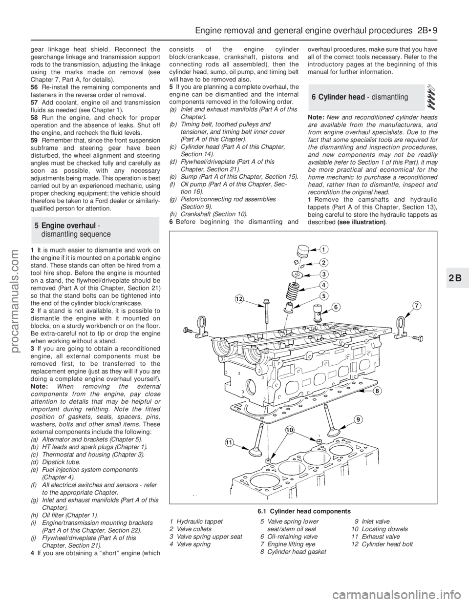
1Remove the camshafts and hydraulic
tappets (Part A of this Chapter, Section 13),
being careful to store the hydraulic tappets as
described (see illustration).
6 Cylinder head - dismantling
5 Engine overhaul-
dismantling sequence
Engine removal and general engine overhaul procedures 2B•9
2B
6.1 Cylinder head components
1 Hydraulic tappet
2 Valve collets
3 Valve spring upper seat
4 Valve spring5 Valve spring lower
seat/stem oil seal
6 Oil-retaining valve
7 Engine lifting eye
8 Cylinder head gasket9 Inlet valve
10 Locating dowels
11 Exhaust valve
12 Cylinder head bolt
procarmanuals.com
Page 102 of 279
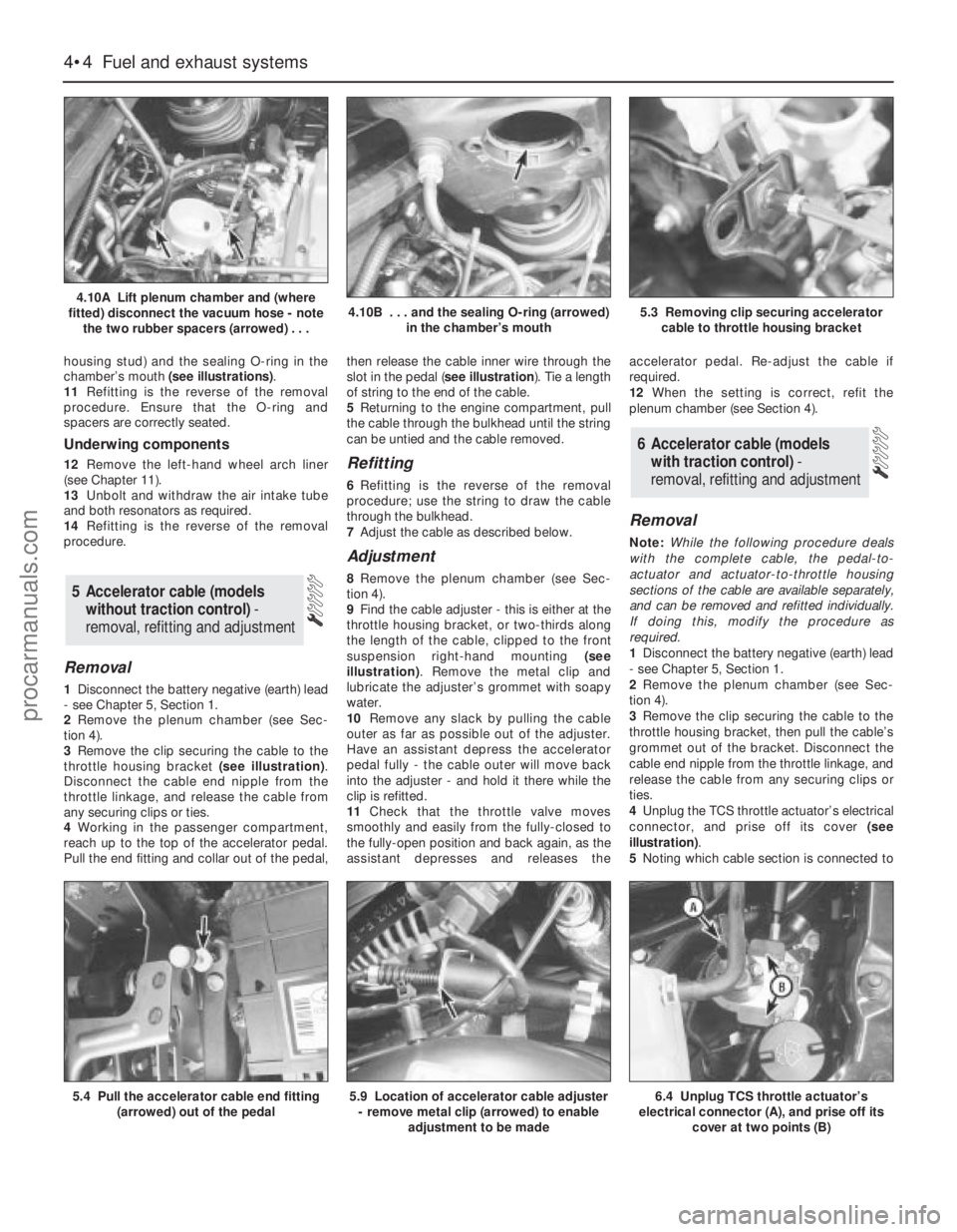
housing stud) and the sealing O-ring in the
chamber’s mouth (see illustrations).
11Refitting is the reverse of the removal
procedure. Ensure that the O-ring and
spacers are correctly seated.
Underwing components
12Remove the left-hand wheel arch liner
(see Chapter 11).
13Unbolt and withdraw the air intake tube
and both resonators as required.
14Refitting is the reverse of the removal
procedure.
Removal
1Disconnect the battery negative (earth) lead
- see Chapter 5, Section 1.
2Remove the plenum chamber (see Sec-
tion 4).
3Remove the clip securing the cable to the
throttle housing bracket (see illustration).
Disconnect the cable end nipple from the
throttle linkage, and release the cable from
any securing clips or ties.
4Working in the passenger compartment,
reach up to the top of the accelerator pedal.
Pull the end fitting and collar out of the pedal,then release the cable inner wire through the
slot in the pedal (see illustration). Tie a length
of string to the end of the cable.
5Returning to the engine compartment, pull
the cable through the bulkhead until the string
can be untied and the cable removed.
Refitting
6Refitting is the reverse of the removal
procedure; use the string to draw the cable
through the bulkhead.
7Adjust the cable as described below.
Adjustment
8Remove the plenum chamber (see Sec-
tion 4).
9Find the cable adjuster - this is either at the
throttle housing bracket, or two-thirds along
the length of the cable, clipped to the front
suspension right-hand mounting (see
illustration). Remove the metal clip and
lubricate the adjuster’s grommet with soapy
water.
10Remove any slack by pulling the cable
outer as far as possible out of the adjuster.
Have an assistant depress the accelerator
pedal fully - the cable outer will move back
into the adjuster - and hold it there while the
clip is refitted.
11Check that the throttle valve moves
smoothly and easily from the fully-closed to
the fully-open position and back again, as the
assistant depresses and releases theaccelerator pedal. Re-adjust the cable if
required.
12When the setting is correct, refit the
plenum chamber (see Section 4).
Removal
Note:While the following procedure deals
with the complete cable, the pedal-to-
actuator and actuator-to-throttle housing
sections of the cable are available separately,
and can be removed and refitted individually.
If doing this, modify the procedure as
required.
1Disconnect the battery negative (earth) lead
- see Chapter 5, Section 1.
2Remove the plenum chamber (see Sec-
tion 4).
3Remove the clip securing the cable to the
throttle housing bracket, then pull the cable’s
grommet out of the bracket. Disconnect the
cable end nipple from the throttle linkage, and
release the cable from any securing clips or
ties.
4Unplug the TCS throttle actuator’s electrical
connector, and prise off its cover (see
illustration).
5Noting which cable section is connected to
6 Accelerator cable (models
with traction control)-
removal, refitting and adjustment
5 Accelerator cable (models
without traction control) -
removal, refitting and adjustment
4•4 Fuel and exhaust systems
4.10A Lift plenum chamber and (where
fitted) disconnect the vacuum hose - note
the two rubber spacers (arrowed) . . .4.10B . . . and the sealing O-ring (arrowed)
in the chamber’s mouth5.3 Removing clip securing accelerator
cable to throttle housing bracket
5.4 Pull the accelerator cable end fitting
(arrowed) out of the pedal5.9 Location of accelerator cable adjuster
- remove metal clip (arrowed) to enable
adjustment to be made6.4 Unplug TCS throttle actuator’s
electrical connector (A), and prise off its
cover at two points (B)
procarmanuals.com
Page 103 of 279
which pulley, disconnect the first cable end
nipple from the throttle actuator’s upper
pulley, then slide the cable outer upwards out
of the actuator housing. Disconnect the
second cable in the same way from the
actuator’s lower pulley.
6Working in the passenger compartment,
reach up to the top of the accelerator pedal.
Pull the end fitting and collar out of the pedal,
then release the cable inner wire through the
slot in the pedal. Tie a length of string to the
end of the cable.
7Returning to the engine compartment, pull
the cable through the bulkhead until the string
can be untied and the pedal-to-actuator cable
removed.
Refitting
8Refitting is the reverse of the removal
procedure. Use the string to draw the pedal-
to-actuator cable through the bulkhead.
Ensure that each cable end is connected to
the correct actuator pulley.
9Adjust both cables as described below.
Adjustment
Note:Both sections of the cable must be
adjusted together, even if only one has been
disturbed.
10Remove the plenum chamber (see
Section 4).
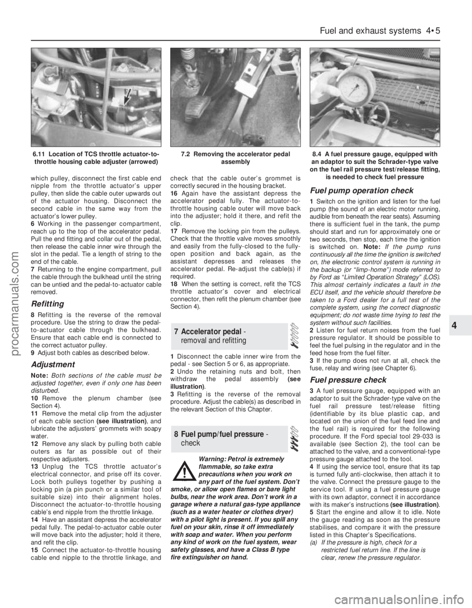
11Remove the metal clip from the adjuster
of each cable section (see illustration), and
lubricate the adjusters’ grommets with soapy
water.
12Remove any slack by pulling both cable
outers as far as possible out of their
respective adjusters.
13Unplug the TCS throttle actuator’s
electrical connector, and prise off its cover.
Lock both pulleys together by pushing a
locking pin (a pin punch or a similar tool of
suitable size) into their alignment holes.
Disconnect the actuator-to-throttle housing
cable’s end nipple from the throttle linkage.
14Have an assistant depress the accelerator
pedal fully. The pedal-to-actuator cable outer
will move back into the adjuster; hold it there,
and refit the clip.
15Connect the actuator-to-throttle housing
cable end nipple to the throttle linkage, andcheck that the cable outer’s grommet is
correctly secured in the housing bracket.
16Again have the assistant depress the
accelerator pedal fully. The actuator-to-
throttle housing cable outer will move back
into the adjuster; hold it there, and refit the
clip.
17Remove the locking pin from the pulleys.
Check that the throttle valve moves smoothly
and easily from the fully-closed to the fully-
open position and back again, as the
assistant depresses and releases the
accelerator pedal. Re-adjust the cable(s) if
required.
18When the setting is correct, refit the TCS
throttle actuator’s cover and electrical
connector, then refit the plenum chamber (see
Section 4).
1Disconnect the cable inner wire from the
pedal - see Section 5 or 6, as appropriate.
2Undo the retaining nuts and bolt, then
withdraw the pedal assembly (see
illustration).
3Refitting is the reverse of the removal
procedure. Adjust the cable(s) as described in
the relevant Section of this Chapter.
Warning: Petrol is extremely
flammable, so take extra
precautions when you work on
any part of the fuel system. Don’t
smoke, or allow open flames or bare light
bulbs, near the work area. Don’t work in a
garage where a natural gas-type appliance
(such as a water heater or clothes dryer)
with a pilot light is present. If you spill any
fuel on your skin, rinse it off immediately
with soap and water. When you perform
any kind of work on the fuel system, wear
safety glasses, and have a Class B type
fire extinguisher on hand.
Fuel pump operation check
1Switch on the ignition and listen for the fuel
pump (the sound of an electric motor running,
audible from beneath the rear seats). Assuming
there is sufficient fuel in the tank, the pump
should start and run for approximately one or
two seconds, then stop, each time the ignition
is switched on. Note:If the pump runs
continuously all the time the ignition is switched
on, the electronic control system is running in
the backup (or “limp-home”) mode referred to
by Ford as “Limited Operation Strategy” (LOS).
This almost certainly indicates a fault in the
ECU itself, and the vehicle should therefore be
taken to a Ford dealer for a full test of the
complete system, using the correct diagnostic
equipment; do not waste time trying to test the
system without such facilities.
2Listen for fuel return noises from the fuel
pressure regulator. It should be possible to
feel the fuel pulsing in the regulator and in the
feed hose from the fuel filter.
3If the pump does not run at all, check the
fuse, relay and wiring (see Chapter 6).
Fuel pressure check
3A fuel pressure gauge, equipped with an
adaptor to suit the Schrader-type valve on the
fuel rail pressure test/release fitting
(identifiable by its blue plastic cap, and
located on the union of the fuel feed line and
the fuel rail) is required for the following
procedure. If the Ford special tool 29-033 is
available (see Section 2), the tool can be
attached to the valve, and a conventional-type
pressure gauge attached to the tool.
4If using the service tool, ensure that its tap
is turned fully anti-clockwise, then attach it to
the valve. Connect the pressure gauge to the
service tool. If using a fuel pressure gauge
with its own adaptor, connect it in accordance
with its maker’s instructions (see illustration).
5Start the engine and allow it to idle. Note
the gauge reading as soon as the pressure
stabilises, and compare it with the pressure
listed in this Chapter’s Specifications.
(a) If the pressure is high, check for a
restricted fuel return line. If the line is
clear, renew the pressure regulator.
8 Fuel pump/fuel pressure -
check
7 Accelerator pedal -
removal and refitting
Fuel and exhaust systems 4•5
4
6.11 Location of TCS throttle actuator-to-
throttle housing cable adjuster (arrowed)7.2 Removing the accelerator pedal
assembly8.4 A fuel pressure gauge, equipped with
an adaptor to suit the Schrader-type valve
on the fuel rail pressure test/release fitting,
is needed to check fuel pressure
procarmanuals.com
Page 178 of 279
Chapter 11 Bodywork and fittings
Body side-trim mouldings and adhesive emblems - removal
and refitting . . . . . . . . . . . . . . . . . . . . . . . . . . . . . . . . . . . . . . . . . . 25
Bonnet - removal, refitting and adjustment . . . . . . . . . . . . . . . . . . . . 8
Bonnet lock - removal, refitting and adjustment . . . . . . . . . . . . . . . . 10
Bonnet release cable and lever - removal and refitting . . . . . . . . . . . 9
Boot lid - removal and refitting . . . . . . . . . . . . . . . . . . . . . . . . . . . . . 18
Boot lid lock components - removal and refitting . . . . . . . . . . . . . . . 19
Bumpers - removal and refitting . . . . . . . . . . . . . . . . . . . . . . . . . . . . 6
Central locking system components - testing, removal and refitting . 23
Centre console - removal and refitting . . . . . . . . . . . . . . . . . . . . . . . 30
Door - removal and refitting . . . . . . . . . . . . . . . . . . . . . . . . . . . . . . . 15
Door handle and lock components - removal and refitting . . . . . . . . 14
Door inner trim panel - removal and refitting . . . . . . . . . . . . . . . . . . 11
Door window glass - removal and refitting . . . . . . . . . . . . . . . . . . . . 12
Door window regulator - removal and refitting . . . . . . . . . . . . . . . . . 13
Exterior mirror and glass - removal and refitting . . . . . . . . . . . . . . . . 16
Facia - removal and refitting . . . . . . . . . . . . . . . . . . . . . . . . . . . . . . . 33
General information . . . . . . . . . . . . . . . . . . . . . . . . . . . . . . . . . . . . . . 1Glovebox - removal and refitting . . . . . . . . . . . . . . . . . . . . . . . . . . . . 32
Interior mirror - removal and refitting . . . . . . . . . . . . . . . . . . . . . . . . 17
Interior trim panels - removal and refitting . . . . . . . . . . . . . . . . . . . . 29
Maintenance - bodywork and underframe . . . . . . . . . . . . . . . . . . . . 2
Maintenance - upholstery and carpets . . . . . . . . . . . . . . . . . . . . . . . 3
Major body damage - repair . . . . . . . . . . . . . . . . . . . . . . . . . . . . . . . 5
Minor body damage - repair . . . . . . . . . . . . . . . . . . . . . . . . . . . . . . . 4
Overhead console - removal and refitting . . . . . . . . . . . . . . . . . . . . . 31
Radiator grille - removal and refitting . . . . . . . . . . . . . . . . . . . . . . . . 7
Seat belts - removal and refitting . . . . . . . . . . . . . . . . . . . . . . . . . . . 28
Seats - removal and refitting . . . . . . . . . . . . . . . . . . . . . . . . . . . . . . . 27
Sunroof - general information and adjustment . . . . . . . . . . . . . . . . . 26
Tailgate - removal and refitting . . . . . . . . . . . . . . . . . . . . . . . . . . . . . 20
Tailgate lock components - removal and refitting . . . . . . . . . . . . . . . 22
Tailgate support strut - removal and refitting . . . . . . . . . . . . . . . . . . 21
Wheel arch liner - removal and refitting . . . . . . . . . . . . . . . . . . . . . . 34
Windscreen and fixed windows - removal and refitting . . . . . . . . . . 24
Torque wrench settingsNm lbf ft
Bonnet and tailgate hinges . . . . . . . . . . . . . . . . . . . . . . . . . . . . . . . . . . . 24 18
Boot lid . . . . . . . . . . . . . . . . . . . . . . . . . . . . . . . . . . . . . . . . . . . . . . . . . . 10 7
Front seat mounting bolts . . . . . . . . . . . . . . . . . . . . . . . . . . . . . . . . . . . . 38 28
Seat belt mounting nuts and bolts . . . . . . . . . . . . . . . . . . . . . . . . . . . . . 38 28
Bumper mounting nuts . . . . . . . . . . . . . . . . . . . . . . . . . . . . . . . . . . . . . . 10 7
11•1
Easy,suitable for
novice with little
experienceFairly easy,suitable
for beginner with
some experienceFairly difficult,suitable
for competent DIY
mechanicDifficult,suitable for
experienced DIY
mechanicVery difficult,
suitable for expert DIY
or professional
Degrees of difficulty
Specifications Contents
11
The bodyshell and underframe on all
models is of all-steel welded construction,
incorporating progressive crumple zones at
the front and rear, and a rigid centre safety
cell. The bulkhead behind the engine
compartment incorporates crash grooves
which determine its energy-absorption
characteristics, and special beams to prevent
the intrusion of the front wheels into the
passenger compartment during a serious
accident. All passenger doors incorporate
side impact bars.
All sheet metal surfaces which are prone tocorrosion are galvanized. The painting
process includes a base colour which closely
matches the final topcoat, so that any stone
damage is not noticeable.
Hatchback, Saloon and Estate versions are
available. The front section of the vehicle up to
the “B” pillar is identical on all models.
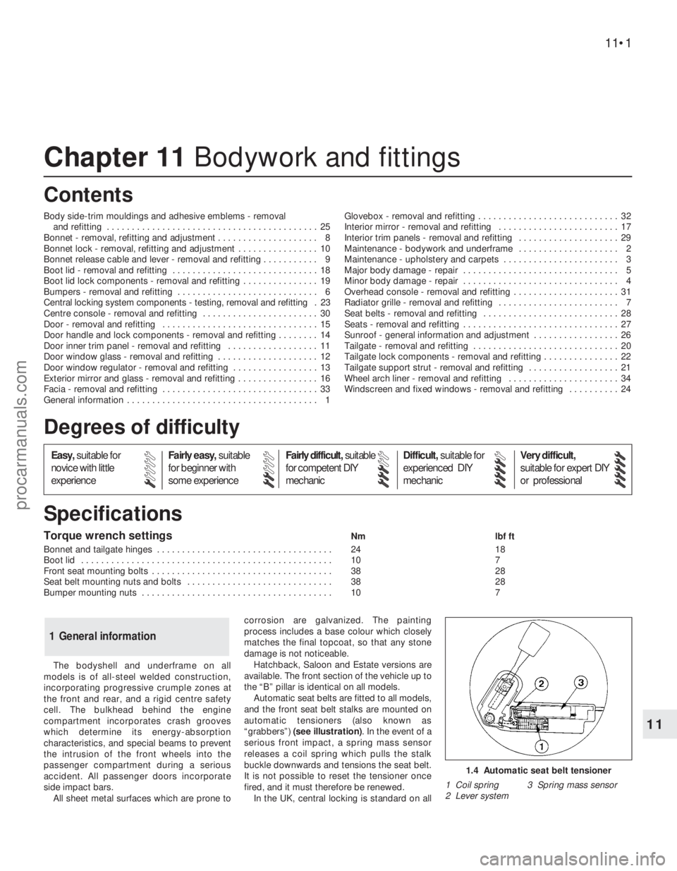
Automatic seat belts are fitted to all models,
and the front seat belt stalks are mounted on
automatic tensioners (also known as
“grabbers”) (see illustration). In the event of a
serious front impact, a spring mass sensor
releases a coil spring which pulls the stalk
buckle downwards and tensions the seat belt.
It is not possible to reset the tensioner once
fired, and it must therefore be renewed.
In the UK, central locking is standard on all
1 General information
1.4 Automatic seat belt tensioner
1 Coil spring 3 Spring mass sensor
2 Lever system
procarmanuals.com
Page 195 of 279
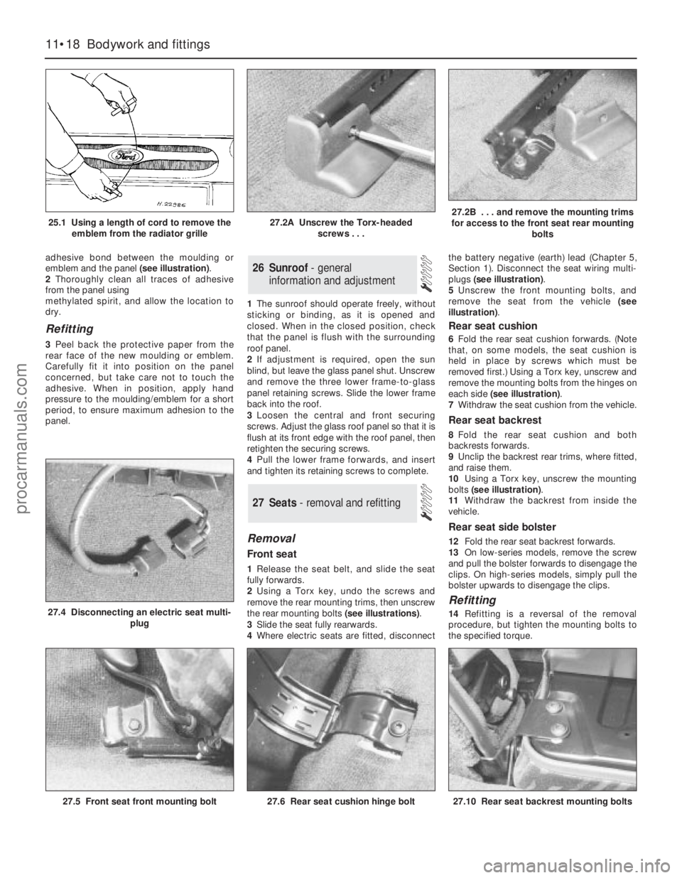
adhesive bond between the moulding or
emblem and the panel (see illustration).
2Thoroughly clean all traces of adhesive
from the panel using
methylated spirit, and allow the location to
dry.
Refitting
3Peel back the protective paper from the
rear face of the new moulding or emblem.
Carefully fit it into position on the panel
concerned, but take care not to touch the
adhesive. When in position, apply hand
pressure to the moulding/emblem for a short
period, to ensure maximum adhesion to the
panel.1The sunroof should operate freely, without
sticking or binding, as it is opened and
closed. When in the closed position, check
that the panel is flush with the surrounding
roof panel.
2If adjustment is required, open the sun
blind, but leave the glass panel shut. Unscrew
and remove the three lower frame-to-glass
panel retaining screws. Slide the lower frame
back into the roof.
3Loosen the central and front securing
screws. Adjust the glass roof panel so that it is
flush at its front edge with the roof panel, then
retighten the securing screws.
4Pull the lower frame forwards, and insert
and tighten its retaining screws to complete.
Removal
Front seat
1Release the seat belt, and slide the seat
fully forwards.
2Using a Torx key, undo the screws and
remove the rear mounting trims, then unscrew
the rear mounting bolts (see illustrations).
3Slide the seat fully rearwards.
4Where electric seats are fitted, disconnectthe battery negative (earth) lead (Chapter 5,
Section 1). Disconnect the seat wiring multi-
plugs (see illustration).
5Unscrew the front mounting bolts, and
remove the seat from the vehicle (see
illustration).
Rear seat cushion
6Fold the rear seat cushion forwards. (Note
that, on some models, the seat cushion is
held in place by screws which must be
removed first.) Using a Torx key, unscrew and
remove the mounting bolts from the hinges on
each side (see illustration).
7Withdraw the seat cushion from the vehicle.
Rear seat backrest
8Fold the rear seat cushion and both
backrests forwards.
9Unclip the backrest rear trims, where fitted,
and raise them.
10Using a Torx key, unscrew the mounting
bolts (see illustration).
11Withdraw the backrest from inside the
vehicle.
Rear seat side bolster
12Fold the rear seat backrest forwards.
13On low-series models, remove the screw
and pull the bolster forwards to disengage the
clips. On high-series models, simply pull the
bolster upwards to disengage the clips.
Refitting
14Refitting is a reversal of the removal
procedure, but tighten the mounting bolts to
the specified torque.
27 Seats - removal and refitting
26 Sunroof - general
information and adjustment
11•18 Bodywork and fittings
25.1 Using a length of cord to remove the
emblem from the radiator grille27.2A Unscrew the Torx-headed
screws . . .27.2B . . . and remove the mounting trims
for access to the front seat rear mounting
bolts
27.5 Front seat front mounting bolt
27.4 Disconnecting an electric seat multi-
plug
27.6 Rear seat cushion hinge bolt27.10 Rear seat backrest mounting bolts
procarmanuals.com
Page 196 of 279
Warning: Be careful when
handling the seat belt tensioning
device (“grabber”). It contains a
powerful spring, which could
cause injury if released in an uncontrolled
fashion. Once fired, the grabber cannot be
reset, and must be renewed. Note also
that seat belts and associated
components which have been subject to
impact loads must be renewed.
Removal
Front seat belt
1Remove the trim from the “B” pillar and the
scuttle.
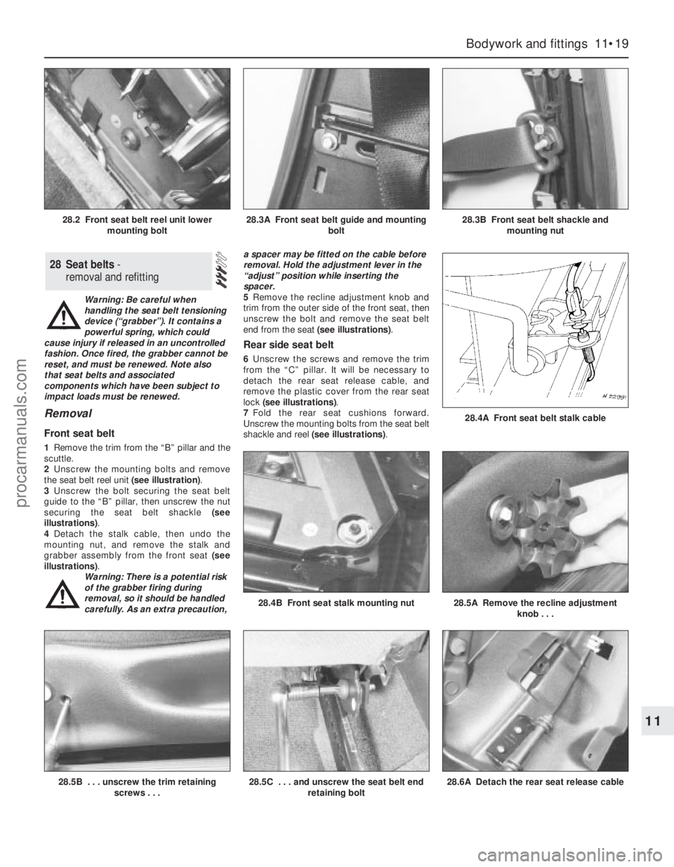
2Unscrew the mounting bolts and remove
the seat belt reel unit (see illustration).
3Unscrew the bolt securing the seat belt
guide to the “B” pillar, then unscrew the nut
securing the seat belt shackle (see
illustrations).
4Detach the stalk cable, then undo the
mounting nut, and remove the stalk and
grabber assembly from the front seat (see
illustrations).
Warning: There is a potential risk
of the grabber firing during
removal, so it should be handled
carefully. As an extra precaution,a spacer may be fitted on the cable before
removal. Hold the adjustment lever in the
“adjust” position while inserting the
spacer.
5Remove the recline adjustment knob and
trim from the outer side of the front seat, then
unscrew the bolt and remove the seat belt
end from the seat (see illustrations).
Rear side seat belt
6Unscrew the screws and remove the trim
from the “C” pillar. It will be necessary to
detach the rear seat release cable, and
remove the plastic cover from the rear seat
lock (see illustrations).
7Fold the rear seat cushions forward.
Unscrew the mounting bolts from the seat belt
shackle and reel (see illustrations).
28 Seat belts -
removal and refitting
Bodywork and fittings 11•19
11
28.5B . . . unscrew the trim retaining
screws . . .28.5C . . . and unscrew the seat belt end
retaining bolt28.6A Detach the rear seat release cable
28.4A Front seat belt stalk cable
28.4B Front seat stalk mounting nut28.5A Remove the recline adjustment
knob . . .
28.2 Front seat belt reel unit lower
mounting bolt28.3A Front seat belt guide and mounting
bolt28.3B Front seat belt shackle and
mounting nut
procarmanuals.com
Page 202 of 279
Chapter 12 Body electrical system
Air bag clock spring - removal and refitting . . . . . . . . . . . . . . . . . . . 30
Air bag control module - removal and refitting . . . . . . . . . . . . . . . . . 29
Air bag unit (driver’s side) - removal and refitting . . . . . . . . . . . . . . . 28
Anti-theft alarm system - general information . . . . . . . . . . . . . . . . . . 20
Auxiliary warning system - general information and
component renewal . . . . . . . . . . . . . . . . . . . . . . . . . . . . . . . . . . . . 19
Battery - check, maintenance and charging . . . . . . . . See Chapter 1
Battery - removal and refitting . . . . . . . . . . . . . . . . . . . See Chapter 5
Bulbs (exterior lights) - renewal . . . . . . . . . . . . . . . . . . . . . . . . . . . . . 5
Bulbs (interior lights) - renewal . . . . . . . . . . . . . . . . . . . . . . . . . . . . . 6
Clock - removal and refitting . . . . . . . . . . . . . . . . . . . . . . . . . . . . . . . 13
Compact disc player - removal and refitting . . . . . . . . . . . . . . . . . . . 25
Cruise control system - general information . . . . . . . . . . . . . . . . . . . 21
Electrical fault finding - general information . . . . . . . . . . . . . . . . . . . 2
Electrical system check . . . . . . . . . . . . . . . . . . . . . . . . See Chapter 1
Exterior light units - removal and refitting . . . . . . . . . . . . . . . . . . . . . 7
Fuses, relays and timer module - testing and renewal . . . . . . . . . . . 3
General information . . . . . . . . . . . . . . . . . . . . . . . . . . . . . . . . . . . . . . 1
Headlight beam alignment - checking and adjustment . . . . . . . . . . 8
Headlight levelling motor - removal and refitting . . . . . . . . . . . . . . . 9Horn - removal and refitting . . . . . . . . . . . . . . . . . . . . . . . . . . . . . . . 14
Instrument panel - removal and refitting . . . . . . . . . . . . . . . . . . . . . . 10
Instrument panel components - removal and refitting . . . . . . . . . . . 11
Radio aerial - removal and refitting . . . . . . . . . . . . . . . . . . . . . . . . . . 27
Radio/cassette player - coding, removal and refitting . . . . . . . . . . . 23
Radio/cassette player power amplifier - removal and refitting . . . . . 24
Speakers - removal and refitting . . . . . . . . . . . . . . . . . . . . . . . . . . . . 26
Speedometer drive cable - removal and refitting . . . . . . . . . . . . . . . 12
Stop-light switch - removal and refitting . . . . . . . . . . . See Chapter 9
Switches - removal and refitting . . . . . . . . . . . . . . . . . . . . . . . . . . . . 4
Tailgate wiper motor assembly - removal and refitting . . . . . . . . . . . 17
TCS inhibition switch - removal and refitting . . . . . . . . See Chapter 9
Trip computer module - removal and refitting . . . . . . . . . . . . . . . . . 18
Windscreen/tailgate washer system and wiper blade
check . . . . . . . . . . . . . . . . . . . . . . . . . . . . . . . . . . . . See Chapter 1
Windscreen/tailgate washer system components - removal
and refitting . . . . . . . . . . . . . . . . . . . . . . . . . . . . . . . . . . . . . . . . . . 22
Windscreen wiper motor and linkage - removal and refitting . . . . . . 16
Wiper arms - removal and refitting . . . . . . . . . . . . . . . . . . . . . . . . . . 15
Fuses (auxiliary fusebox in engine compartment)
Note:Fuse ratings and circuits are liable to change from year to year. Consult the handbook supplied with the vehicle, or consult a Ford dealer,
for specific information.
Fuse No Rating Colour Circuit(s) protected
1 80 Black . . . . . . . . . . . . . . . . . . . . . . . . . . Power supply to main fusebox
2 60 Yellow . . . . . . . . . . . . . . . . . . . . . . . . . Radiator electric cooling fans
3 60 Yellow . . . . . . . . . . . . . . . . . . . . . . . . . Diesel engine glow plugs and/or ABS braking system
4 20 Yellow . . . . . . . . . . . . . . . . . . . . . . . . . Ignition system, or ignition and daytime running lights
5 30 Light green . . . . . . . . . . . . . . . . . . . . . . Heated windscreen (left-hand side)
6 30 Light green . . . . . . . . . . . . . . . . . . . . . . Heated windscreen (right-hand side)
7 30 Light green . . . . . . . . . . . . . . . . . . . . . . ABS braking system
8 30 Light green . . . . . . . . . . . . . . . . . . . . . . Air conditioning compressor/heated seats or air conditioning
compressor/daytime running lights
9 20 Light blue . . . . . . . . . . . . . . . . . . . . . . . ECU (petrol), Cold start solenoid (Diesel)
10 20 Light blue . . . . . . . . . . . . . . . . . . . . . . . Ignition switch
11 3 Violet . . . . . . . . . . . . . . . . . . . . . . . . . . ECU memory
12 15 Light blue . . . . . . . . . . . . . . . . . . . . . . . Horn and hazard flasher warning system
13 15 Light blue . . . . . . . . . . . . . . . . . . . . . . . Oxygen sensor
14 15 Light blue . . . . . . . . . . . . . . . . . . . . . . . Fuel pump
15 10 Red . . . . . . . . . . . . . . . . . . . . . . . . . . . Dipped beam headlight (right-hand side)
16 10 Red . . . . . . . . . . . . . . . . . . . . . . . . . . . Dipped beam headlight (left-hand side)
17 10 Red . . . . . . . . . . . . . . . . . . . . . . . . . . . Main beam headlight (right-hand side)
18 10 Red . . . . . . . . . . . . . . . . . . . . . . . . . . . Main beam headlight (left-hand side)
12•1
Easy,suitable for
novice with little
experienceFairly easy,suitable
for beginner with
some experienceFairly difficult,suitable
for competent DIY
mechanicDifficult,suitable for
experienced DIY
mechanicVery difficult,
suitable for expert DIY
or professional
Degrees of difficulty
Specifications Contents
12
procarmanuals.com
Page 214 of 279
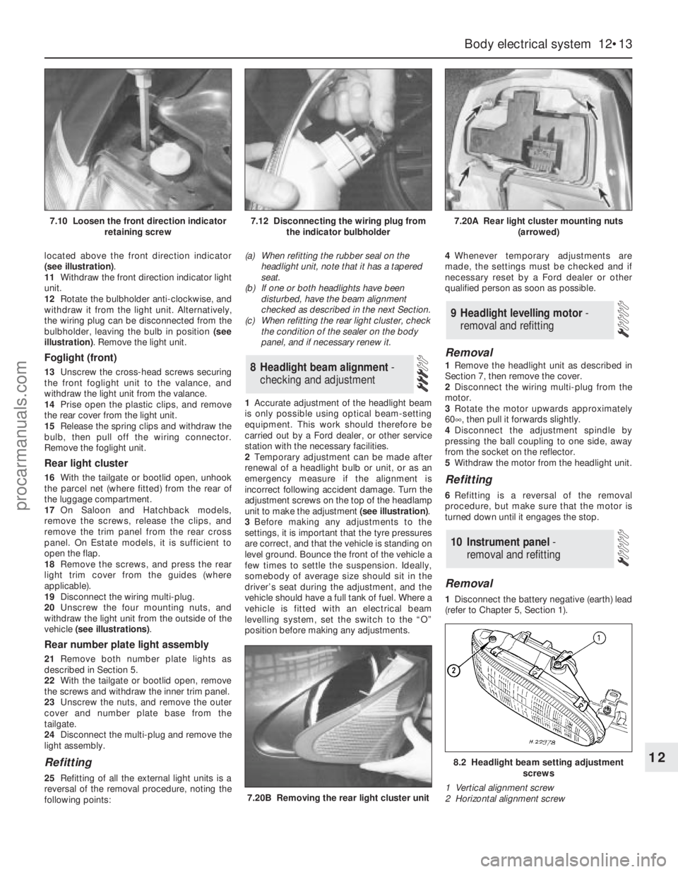
located above the front direction indicator
(see illustration).
11Withdraw the front direction indicator light
unit.
12Rotate the bulbholder anti-clockwise, and
withdraw it from the light unit. Alternatively,
the wiring plug can be disconnected from the
bulbholder, leaving the bulb in position (see
illustration). Remove the light unit.
Foglight (front)
13Unscrew the cross-head screws securing
the front foglight unit to the valance, and
withdraw the light unit from the valance.
14Prise open the plastic clips, and remove
the rear cover from the light unit.
15Release the spring clips and withdraw the
bulb, then pull off the wiring connector.
Remove the foglight unit.
Rear light cluster
16With the tailgate or bootlid open, unhook
the parcel net (where fitted) from the rear of
the luggage compartment.
17On Saloon and Hatchback models,
remove the screws, release the clips, and
remove the trim panel from the rear cross
panel. On Estate models, it is sufficient to
open the flap.
18Remove the screws, and press the rear
light trim cover from the guides (where
applicable).
19Disconnect the wiring multi-plug.
20Unscrew the four mounting nuts, and
withdraw the light unit from the outside of the
vehicle (see illustrations).
Rear number plate light assembly
21Remove both number plate lights as
described in Section 5.
22With the tailgate or bootlid open, remove
the screws and withdraw the inner trim panel.
23Unscrew the nuts, and remove the outer
cover and number plate base from the
tailgate.
24Disconnect the multi-plug and remove the
light assembly.
Refitting
25Refitting of all the external light units is a
reversal of the removal procedure, noting the
following points:(a) When refitting the rubber seal on the
headlight unit, note that it has a tapered
seat.
(b) If one or both headlights have been
disturbed, have the beam alignment
checked as described in the next Section.
(c) When refitting the rear light cluster, check
the condition of the sealer on the body
panel, and if necessary renew it.
1Accurate adjustment of the headlight beam
is only possible using optical beam-setting
equipment. This work should therefore be
carried out by a Ford dealer, or other service
station with the necessary facilities.
2Temporary adjustment can be made after
renewal of a headlight bulb or unit, or as an
emergency measure if the alignment is
incorrect following accident damage. Turn the
adjustment screws on the top of the headlamp
unit to make the adjustment (see illustration).
3Before making any adjustments to the
settings, it is important that the tyre pressures
are correct, and that the vehicle is standing on
level ground. Bounce the front of the vehicle a
few times to settle the suspension. Ideally,
somebody of average size should sit in the
driver’s seat during the adjustment, and the
vehicle should have a full tank of fuel. Where a
vehicle is fitted with an electrical beam
levelling system, set the switch to the “O”
position before making any adjustments.4Whenever temporary adjustments are
made, the settings must be checked and if
necessary reset by a Ford dealer or other
qualified person as soon as possible.
Removal
1Remove the headlight unit as described in
Section 7, then remove the cover.
2Disconnect the wiring multi-plug from the
motor.
3Rotate the motor upwards approximately
60°, then pull it forwards slightly.
4Disconnect the adjustment spindle by
pressing the ball coupling to one side, away
from the socket on the reflector.
5Withdraw the motor from the headlight unit.
Refitting
6Refitting is a reversal of the removal
procedure, but make sure that the motor is
turned down until it engages the stop.
Removal
1Disconnect the battery negative (earth) lead
(refer to Chapter 5, Section 1).
10 Instrument panel -
removal and refitting
9 Headlight levelling motor -
removal and refitting
8 Headlight beam alignment-
checking and adjustment
Body electrical system 12•13
12
7.20B Removing the rear light cluster unit
8.2 Headlight beam setting adjustment
screws
1 Vertical alignment screw
2 Horizontal alignment screw
7.10 Loosen the front direction indicator
retaining screw7.12 Disconnecting the wiring plug from
the indicator bulbholder7.20A Rear light cluster mounting nuts
(arrowed)
procarmanuals.com