1993 CHEVROLET PLYMOUTH ACCLAIM width
[x] Cancel search: widthPage 2371 of 2438
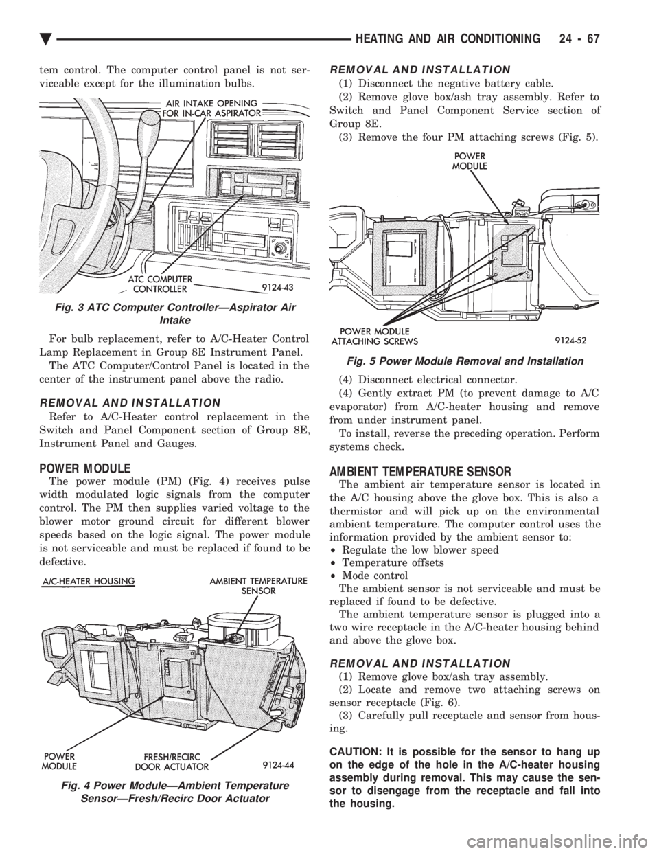
tem control. The computer control panel is not ser-
viceable except for the illumination bulbs. For bulb replacement, refer to A/C-Heater Control
Lamp Replacement in Group 8E Instrument Panel. The ATC Computer/Control Panel is located in the
center of the instrument panel above the radio.
REMOVAL AND INSTALLATION
Refer to A/C-Heater control replacement in the
Switch and Panel Component section of Group 8E,
Instrument Panel and Gauges.
POWER MODULE
The power module (PM) (Fig. 4) receives pulse
width modulated logic signals from the computer
control. The PM then supplies varied voltage to the
blower motor ground circuit for different blower
speeds based on the logic signal. The power module
is not serviceable and must be replaced if found to be
defective.
REMOVAL AND INSTALLATION
(1) Disconnect the negative battery cable.
(2) Remove glove box/ash tray assembly. Refer to
Switch and Panel Component Service section of
Group 8E. (3) Remove the four PM attaching screws (Fig. 5).
(4) Disconnect electrical connector.
(4) Gently extract PM (to prevent damage to A/C
evaporator) from A/C-heater housing and remove
from under instrument panel. To install, reverse the preceding operation. Perform
systems check.
AMBIENT TEMPERATURE SENSOR
The ambient air temperature sensor is located in
the A/C housing above the glove box. This is also a
thermistor and will pick up on the environmental
ambient temperature. The computer control uses the
information provided by the ambient sensor to:
² Regulate the low blower speed
² Temperature offsets
² Mode control
The ambient sensor is not serviceable and must be
replaced if found to be defective. The ambient temperature sensor is plugged into a
two wire receptacle in the A/C-heater housing behind
and above the glove box.
REMOVAL AND INSTALLATION
(1) Remove glove box/ash tray assembly.
(2) Locate and remove two attaching screws on
sensor receptacle (Fig. 6). (3) Carefully pull receptacle and sensor from hous-
ing.
CAUTION: It is possible for the sensor to hang up
on the edge of the hole in the A/C-heater housing
assembly during removal. This may cause the sen-
sor to disengage from the receptacle and fall into
the housing.
Fig. 3 ATC Computer ControllerÐAspirator Air Intake
Fig. 4 Power ModuleÐAmbient TemperatureSensorÐFresh/Recirc Door Actuator
Fig. 5 Power Module Removal and Installation
Ä HEATING AND AIR CONDITIONING 24 - 67
Page 2402 of 2438
During the cold start warm-up period and the hot
start time delay, the PCM does not energize the so-
lenoid. When de-energized, no vapors are purged.
The PCM de-energizes the solenoid during open loop
operation. The engine enters closed loop operation after it
reaches a specified temperature and the time delay
ends. During closed loop operation, the PCM ener-
gizes and de-energizes the solenoid approximately 5
to 10 times per second, depending upon operating
conditions. The PCM varies the vapor flow rate by
changing solenoid pulse width. Pulse width is the
amount of time the solenoid energizes. The PCM ad-
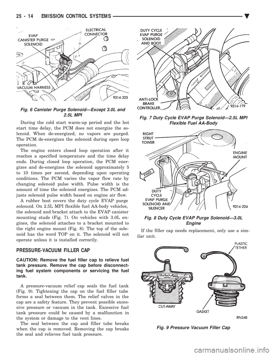
justs solenoid pulse width based on engine air flow. A rubber boot covers the duty cycle EVAP purge
solenoid. On 2.5L MPI flexible fuel AA-body vehicles,
the solenoid and bracket attach to the EVAP canister
mounting studs (Fig. 7). On vehicles with 3.0L en-
gines, the solenoid attaches to a bracket mounted to
the right engine mount (Fig. 8). The top of the sole-
noid has the word TOP on it. The solenoid will not
operate unless it is installed correctly.
PRESSURE-VACUUM FILLER CAP
CAUTION: Remove the fuel filler cap to relieve fuel
tank pressure. Remove the cap before disconnect-
ing fuel system components or servicing the fuel
tank.
A pressure-vacuum relief cap seals the fuel tank
(Fig. 9). Tightening the cap on the fuel filler tube
forms a seal between them. The relief valves in the
cap are a safety feature. They prevent possible exces-
sive pressure or vacuum in the tank. Excessive fuel
tank pressure could be caused by a malfunction in
the system or damage to the vent lines. The seal between the cap and filler tube breaks
when the cap is removed. Removing the cap breaks
the seal and relieves fuel tank pressure. If the filler cap needs replacement, only use a sim-
ilar unit.
Fig. 6 Canister Purge SolenoidÐExcept 3.0L and 2.5L MPI
Fig. 7 Duty Cycle EVAP Purge SolenoidÐ2.5L MPIFlexible Fuel AA-Body
Fig. 8 Duty Cycle EVAP Purge SolenoidÐ3.0L Engine
Fig. 9 Pressure Vacuum Filler Cap
25 - 14 EMISSION CONTROL SYSTEMS Ä
Page 2406 of 2438
air entering the outer end of snorkel is 60ÉC (140ÉF.) or
higher, the door should be in the down (heat off)
position. (4) Remove the air cleaner from the engine and
allow it to cool down to 46ÉC (115ÉF). With 20 inches of
vacuum applied to the sensor, the door should be in the
up (heat on position). If the door does not rise to the
heat on position, check the vacuum diaphragm for
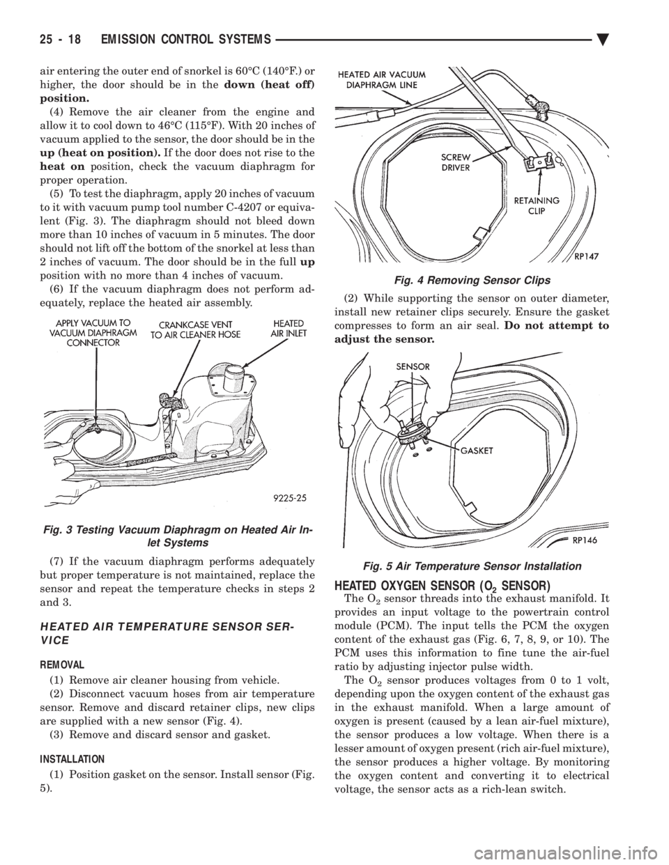
proper operation. (5) To test the diaphragm, apply 20 inches of vacuum
to it with vacuum pump tool number C-4207 or equiva-
lent (Fig. 3). The diaphragm should not bleed down
more than 10 inches of vacuum in 5 minutes. The door
should not lift off the bottom of the snorkel at less than
2 inches of vacuum. The door should be in the full up
position with no more than 4 inches of vacuum. (6) If the vacuum diaphragm does not perform ad-
equately, replace the heated air assembly.
(7) If the vacuum diaphragm performs adequately
but proper temperature is not maintained, replace the
sensor and repeat the temperature checks in steps 2
and 3.
HEATED AIR TEMPERATURE SENSOR SER- VICE
REMOVAL
(1) Remove air cleaner housing from vehicle.
(2) Disconnect vacuum hoses from air temperature
sensor. Remove and discard retainer clips, new clips
are supplied with a new sensor (Fig. 4). (3) Remove and discard sensor and gasket.
INSTALLATION (1) Position gasket on the sensor. Install sensor (Fig.
5). (2) While supporting the sensor on outer diameter,
install new retainer clips securely. Ensure the gasket
compresses to form an air seal. Do not attempt to
adjust the sensor.
HEATED OXYGEN SENSOR (O2SENSOR)
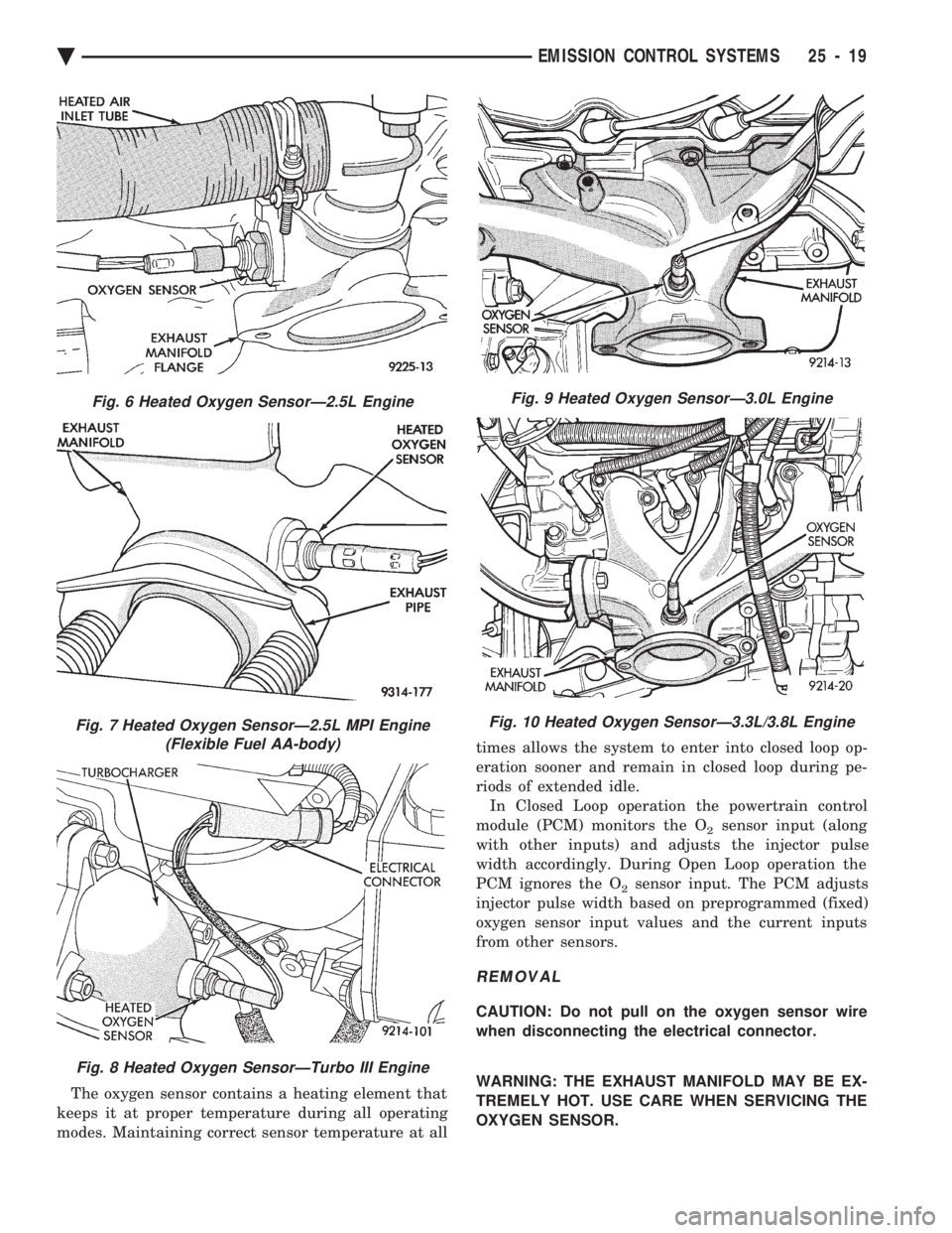
The O2sensor threads into the exhaust manifold. It
provides an input voltage to the powertrain control
module (PCM). The input tells the PCM the oxygen
content of the exhaust gas (Fig. 6, 7, 8, 9, or 10). The
PCM uses this information to fine tune the air-fuel
ratio by adjusting injector pulse width. The O
2sensor produces voltages from 0 to 1 volt,
depending upon the oxygen content of the exhaust gas
in the exhaust manifold. When a large amount of
oxygen is present (caused by a lean air-fuel mixture),
the sensor produces a low voltage. When there is a
lesser amount of oxygen present (rich air-fuel mixture),
the sensor produces a higher voltage. By monitoring
the oxygen content and converting it to electrical
voltage, the sensor acts as a rich-lean switch.
Fig. 3 Testing Vacuum Diaphragm on Heated Air In- let Systems
Fig. 4 Removing Sensor Clips
Fig. 5 Air Temperature Sensor Installation
25 - 18 EMISSION CONTROL SYSTEMS Ä
Page 2407 of 2438
The oxygen sensor contains a heating element that
keeps it at proper temperature during all operating
modes. Maintaining correct sensor temperature at all times allows the system to enter into closed loop op-
eration sooner and remain in closed loop during pe-
riods of extended idle.
In Closed Loop operation the powertrain control
module (PCM) monitors the O
2sensor input (along
with other inputs) and adjusts the injector pulse
width accordingly. During Open Loop operation the
PCM ignores the O
2sensor input. The PCM adjusts
injector pulse width based on preprogrammed (fixed)
oxygen sensor input values and the current inputs
from other sensors.
REMOVAL
CAUTION: Do not pull on the oxygen sensor wire
when disconnecting the electrical connector.
WARNING: THE EXHAUST MANIFOLD MAY BE EX-
TREMELY HOT. USE CARE WHEN SERVICING THE
OXYGEN SENSOR.
Fig. 6 Heated Oxygen SensorÐ2.5L Engine
Fig. 7 Heated Oxygen SensorÐ2.5L MPI Engine (Flexible Fuel AA-body)
Fig. 8 Heated Oxygen SensorÐTurbo III Engine
Fig. 9 Heated Oxygen SensorÐ3.0L Engine
Fig. 10 Heated Oxygen SensorÐ3.3L/3.8L Engine
Ä EMISSION CONTROL SYSTEMS 25 - 19
Page 2437 of 2438
Page 9
03/30/99
Rev. 0
4.0 Using The Acrobat Reader
4.1 Acrobat Reader On-Line Help
The complete user help file can be accessed by selecting the
Help Menu option and then Reader Online Guide option within
the Acrobat Reader application.
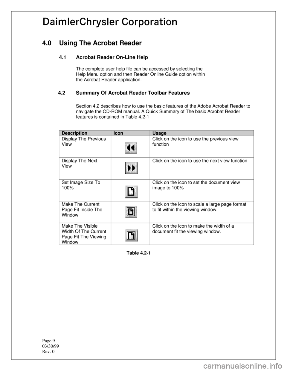
4.2 Summary Of Acrobat Reader Toolbar Features
Section 4.2 describes how to use the basic features of the Adobe Acrobat Reader to
navigate the CD-ROM manual. A Quick Summary of The basic Acrobat Reader
features is contained in Table 4.2-1
DescriptionIconUsage
Display The Previous
View Click on the icon to use the previous view
function
Display The Next
View Click on the icon to use the next view function
Set Image Size To
100% Click on the icon to set the document view
image to 100%
Make The Current
Page Fit Inside The
Window Click on the icon to scale a large page format
to fit within the viewing window.
Make The Visible
Width Of The Current
Page Fit The Viewing
Window Click on the icon to make the width of a
document fit the viewing window.
Table 4.2-1
Page 2438 of 2438
10
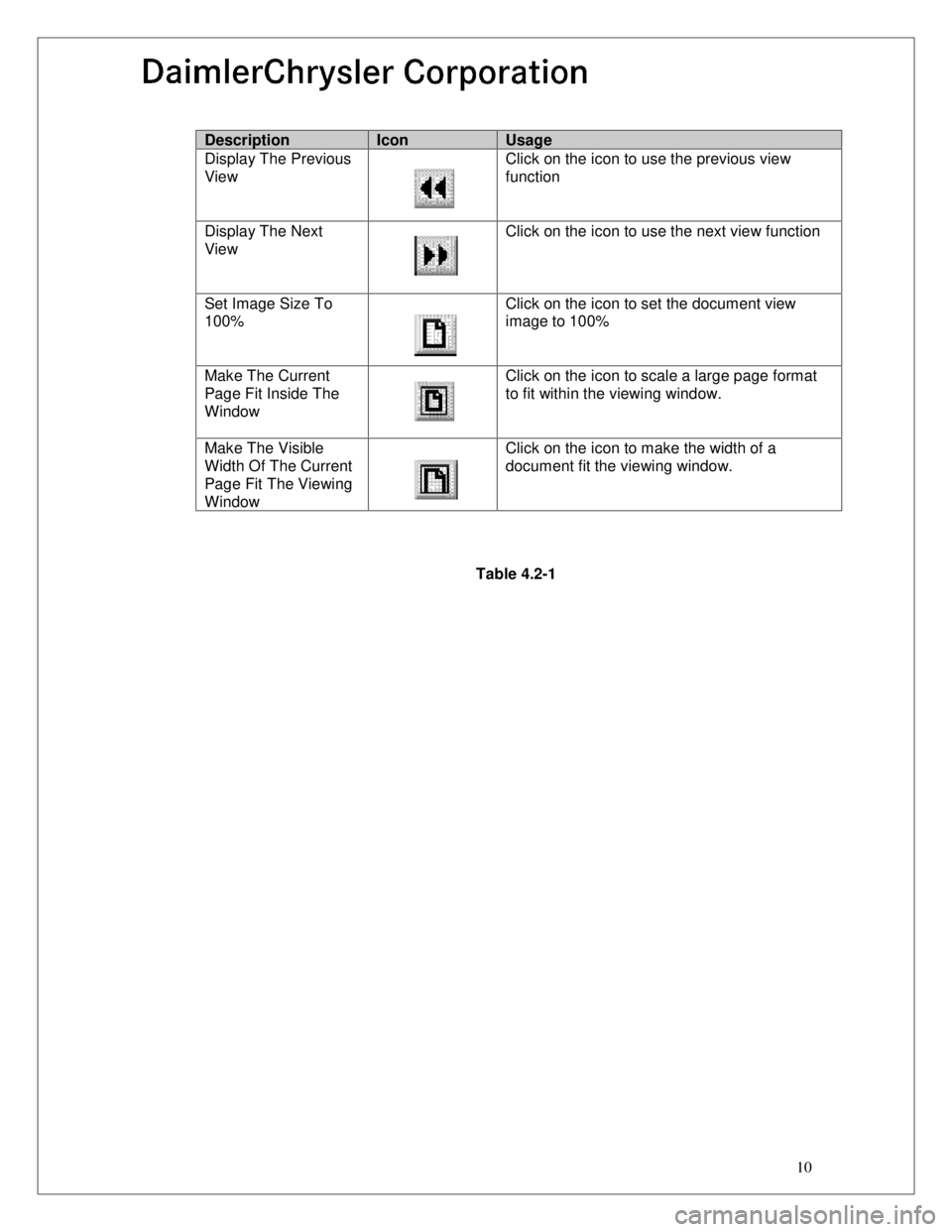
DescriptionIconUsage
Display The Previous
View Click on the icon to use the previous view
function
Display The Next
View Click on the icon to use the next view function
Set Image Size To
100% Click on the icon to set the document view
image to 100%
Make The Current
Page Fit Inside The
Window Click on the icon to scale a large page format
to fit within the viewing window.
Make The Visible
Width Of The Current
Page Fit The Viewing
Window Click on the icon to make the width of a
document fit the viewing window.
Table 4.2-1