1993 CHEVROLET PLYMOUTH ACCLAIM width
[x] Cancel search: widthPage 170 of 2438

Kelsey Hayes ÐLeading/trailing shoes; Remove
holddown springs (Fig. 7). Pull assembly down and
away to remove shoes from support plate (Fig. 8). Re-
move brake shoe springs and adjusting screw assem-
bly.
Varga ÐLeading shoe; Remove the upper shoe to
shoe return spring (Fig. 3). The leading shoe hold
down spring (Fig. 7). And the shoe to shoe spring at
the anchor plate (Fig. 3). Remove shoe and adjuster
assembly. Varga ÐTrailing shoe; Remove holddown spring
and lower shoe-to-anchor plate spring. Kelsey Hayes: Remove park brake lever from
trailing brake shoe by disengaging the retainer clip
(Fig. 9). Be sure not to lose park brake lever wave
washer.
CLEANING AND INSPECTION
Clean metal portion of brake shoes. Check to see if
shoes are bent. Lining should show contact across entire width and
from heel to toe, otherwise replace. Shoes with lack of contact at toe or heel maybe im-
properly ground. Clean and inspect support and adjusting screws.
Apply a thin coat of Mopar Multi-Purpose Lubricant
or equivalent to the threads of the self adjuster (Fig.
10). Replace adjusting screw if corroded.
Fig. 6 Disconnect Parking Brake Cable
Fig. 7 Remove or Install Holddown Springs
Fig. 8 Remove or Install Brake Shoes
Fig. 9 Remove or Install Park Brake Lever Retainer
5 - 20 BRAKES Ä
Page 1567 of 2438
ENGINE
CONTENTS
page page
2.2/2.5L ENGINES ....................... 8
3.0L ENGINE .......................... 66 3.3/3.8L ENGINE
....................... 98
STANDARD SERVICE PROCEDURES ......... 1
STANDARD SERVICE PROCEDURES INDEX
page page
Crankshaft Sprocket Bolt Access Plug .......... 2
Engine Performance ....................... 2
Form-In-Place Gaskets ..................... 1
Honing Cylinder Bores ..................... 2
Hydrostatic Locked Engine .................. 5 Lash Adjuster (Tappet) Noise Diagnosis
........ 4
Measuring Main Bearing Clearance and Connecting Rod Bearing Clearance ................... 3
Repair of Damaged or Worn Threads .......... 4
FORM-IN-PLACE GASKETS
There are numerous places where form-in-place
gaskets are used on the engine. Care must be taken
when applying form-in-place gaskets to assure ob-
taining the desired results. Bead size, continuity, and
location are of great importance. Too thin a bead can
result in leakage while too much can result in spill-
over which can break off and obstruct fluid feed
lines. A continuous bead of the proper width is essen-
tial to obtain a leak-free joint. Two types of form-in-place gasket materials are
used in the engine area. Mopar Silicone Rubber Ad-
hesive Sealant and anaerobic gasket materials, each
have different properties and cannot be used inter-
changeably.
MOPAR SILICONE RUBBER ADHESIVE SEALANT
Mopar Silicone Rubber Adhesive Sealant or equiv-
alent, normally black in color, is available in three
ounce tubes. Moisture in the air causes the Mopar
Silicone Rubber Adhesive Sealant material to cure.
This material is normally used on flexible metal
flanges. It has a shelf life of one year and will not
properly cure if over age. Always inspect the package
for the expiration date before use.
MOPAR GASKET MAKER
MOPAR Gasket Maker is an anaerobic type gasket
material normally red in color. The material cures in
the absence of air when squeezed between two metal-
lic surfaces. It will not cure if left in the uncovered tube. It is normally red in color. The anaerobic ma-
terial is for use between two machined surfaces. Do
not used on flexible metal flanges.
GASKET DISASSEMBLY
Parts assembled with form-in-place gaskets may be
disassembled without unusual effort. In some in-
stances, it may be necessary to lightly tap the part
with a mallet or other suitable tool to break the seal
between the mating surfaces. A flat gasket scraper
may also be lightly tapped into the joint but care
must be taken not to damage the mating surfaces.
SURFACE PREPARATION
Scrape clean or wire brush all gasket surfaces re-
moving all loose material. Inspect stamped parts to
assure gasket rails are flat. Flatten rails with a ham-
mer on a flat plate if required. Gasket surfaces must
be free of oil and dirt. Make sure old gasket material
is removed from blind attaching holes.
FORM-IN-PLACE GASKET APPLICATION
Assembling parts using a form-in-place gasket re-
quires care but it's easier then using precut gaskets. MOPAR Gasket Maker material should be applied
sparingly 1mm(0.040 inch.) diameter or less of seal-
ant to one gasket surface. Be certain the material
surrounds each mounting hole. Excess material can
easily be wiped off. Components should be torqued in
place within 15 minutes. The use of a locating dowel
is recommended during assembly to prevent smear-
ing the material off location.
Ä ENGINE 9 - 1
Page 1570 of 2438
REMOVE ALL SHIMS BEFORE REASSEM-
BLING ENGINE ALTERNATIVE METHOD Ð With the weight of
the crankshaft being supported by a jack under the
counterweight adjacent to the bearing being checked. (3) Place a piece of Plastigage across the entire
width of the bearing shell in the cap approximately
6.35 mm (1/4 inch) off center and away from the oil
holes (Fig. 2). (In addition, suspect areas can be
checked by placing the Plastigage in the suspect area).
Torque the bearing cap bolts of the bearing being
checked to the proper specifications. (4) Remove the bearing cap and compare the width
of the flattened Plastigage (Fig. 3) with the metric scale
provided on the package. Locate the band closest to the
same width. This band shows the amount of clearance
in thousandths of a millimeter. Differences in readings
between the ends indicate the amount of taper present.
Record all readings taken. Refer to Engine Specifica-
tions. Plastic-Gage generally is accompanied by
two scales. One scale is in inches, the other is a
metric scale. (5) Plastigage is available in a variety of clearance
ranges. The 0.025-0.076mm (.001-.003 inch) is usually
the most appropriate for checking engine bearing
proper specifications.
CONNECTING ROD BEARING CLEARANCE
Engine crankshaft bearing clearances can be deter-
mined by use of Plastigage or equivalent. The following
is the recommended procedure for the use of Plasti-
gage: (1) Rotate the crankshaft until the connecting rod to
be checked is at the bottom of its stroke. (2) Remove oil film from surface to be checked.
Plastigage is soluble in oil. (3) Place a piece of Plastigage across the entire
width of the bearing shell in the bearing cap approxi-
mately 6.35 mm (1/4 inch.) off center and away from
the oil hole (Fig. 2). In addition, suspect areas can be
checked by placing plastigage in the suspect area. (4) Before assembling the rod cap with Plastigage in
place, the crankshaft must be rotated until the con-
necting being checked starts moving toward the top of
the engine. Only then should the cap be assembled and
torqued to specifications. Do not rotate the crank-
shaft while assembling the cap or the Plastigage
may be smeared, giving inaccurate results. (5) Remove the bearing cap and compare the width
of the flattened Plastigage (Fig. 3) with the metric
scale provided on the package. Locate the band closest
to the same width. This band shows the amount
of clearance in thousandths of a millimeter. Differences
in readings between the ends indicate the amount
of taper present. Record all readings taken.
Refer to Engine Specifications. Plastigage generally is accompanied by two scales. One scale is in
inches, the other is a metric scale. (6) Plastigage is available in a variety of clearance
ranges. The 0.025-0.076mm (.001-.003 inch) is usually
the most appropriate for checking engine bearing
proper specifications.
LASH ADJUSTER (TAPPET) NOISE DIAGNOSIS
A tappet-like noise may be produced from several
items. Check the following items. (1) Engine oil level too high or too low. This may
cause aerated oil to enter the adjusters and cause them
to be spongy. (2) Insufficient running time after rebuilding cylin-
der head. Low speed running up to 1 hour may be
required. During this time, turn engine off and let set for a few
minutes before restarting. Repeat this several times
after engine has reached normal operating tempera-
ture. (3) Low oil pressure.
(4) The oil restrictor pressed into the vertical oil
passage to the cylinder head of Balance Shaft Engines
Only is plugged with debris. (5) Air ingested into oil due to broken or cracked oil
pump pick up. (6) Worn valve guides.
(7) Rocker arm ears contacting valve spring retainer
(2.2/2.5L engines). (8) Rocker arm loose, adjuster or tappet stuck or at
maximum extension and still leaves lash in the system. (9) Faulty lash adjuster or tappet.(a) Check for sponginess while still installed in
engine. Depress part of rocker arm just over adjuster
or pushrod . Normal adjusters should feel very firm.
Spongy adjusters can be depressed to the bottomed
position easily. (b) Remove suspected lash adjuster or tappet, pry
off retainer cap or snap ring and disassemble. Do
not reuse retainer caps . Do not interchange parts
and make sure that care and cleanliness is exercised
in the handling of parts. (c) Clean out dirt and varnish with solvent.
(d) Reassemble with engine oil.
(e) Check for sponginess.
(f) If still spongy, replace with new adjuster.
REPAIR OF DAMAGED OR WORN THREADS
Damaged or worn threads (including aluminum head
spark plug threads) can be repaired. Essentially, this
repair consists of drilling out worn or damaged
threads, tapping the hole with a special Heli-Coil (or
equivalent) Tap, and installing an insert into the
tapped hole. This brings the hole back to its original
thread size.
9 - 4 ENGINE Ä
Page 1595 of 2438
(2) Inspect each valve spring for squareness with a
steel square and surface plate, test springs from both
ends. If the spring is more than 1.5mm (1/16 inch)
out of square, install a new spring.
REFACING VALVES AND VALVE SEATS (1) The intake and exhaust valve seats and valve
face have a 45 degree angle.
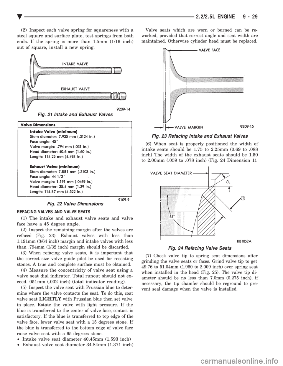
(2) Inspect the remaining margin after the valves are
refaced (Fig. 23). Exhaust valves with less than
1.191mm (3/64 inch) margin and intake valves with less
than .794mm (1/32 inch) margin should be discarded. (3) When refacing valve seats, it is important that
the correct size valve guide pilot be used for reseating
stones. A true and complete surface must be obtained.
(4) Measure the concentricity of valve seat using a
valve seat dial indicator. Total runout should not ex-
ceed. 051mm (.002 inch) (total indicator reading).
(5) Inspect the valve seat with Prussian blue to deter-
mine where the valve contacts the seat. To do this, coat
valve seat LIGHTLY with Prussian blue then set valve
in place. Rotate the valve with light pressure. If the
blue is transferred to the center of valve face, contact is
satisfactory. If the blue is transferred to top edge of the
valve face, lower valve seat with a 15 degrees stone. If
the blue is transferred to the bottom edge of valve face
raise valve seat with a 65 degrees stone.
² Intake valve seat diameter 40.45mm (1.593 inch)
² Exhaust valve seat diameter 34.84mm (1.371 inch)
Valve seats which are worn or burned can be re-
worked, provided that correct angle and seat width are
maintained. Otherwise cylinder head must be replaced.
(6) When seat is properly positioned the width of
intake seats should be 1.75 to 2.25mm (0.69 to .088
inch) The width of the exhaust seats should be 1.50
to 2.00mm (.059 to .078 inch) (Fig. 24 Dimension 1).
(7) Check valve tip to spring seat dimensions after
grinding the valve seats or faces. Grind valve tip to get
49.76 to 51.04mm (1.960 to 2.009 inch) over spring seat
when installed in the head (Fig. 25). The valve tip di-
ameter should be no less than 7.0mm (0.275 inch), if
necessary, the tip chamfer should be reground to pre-
vent seal damage when the valve is installed.
Fig. 21 Intake and Exhaust Valves
Fig. 22 Valve Dimensions
Fig. 23 Refacing Intake and Exhaust Valves
Fig. 24 Refacing Valve Seats
Ä 2.2/2.5L ENGINE 9 - 29
Page 1605 of 2438
REFACING VALVES AND VALVE SEATS
(1) The intake and exhaust valve seats and valve
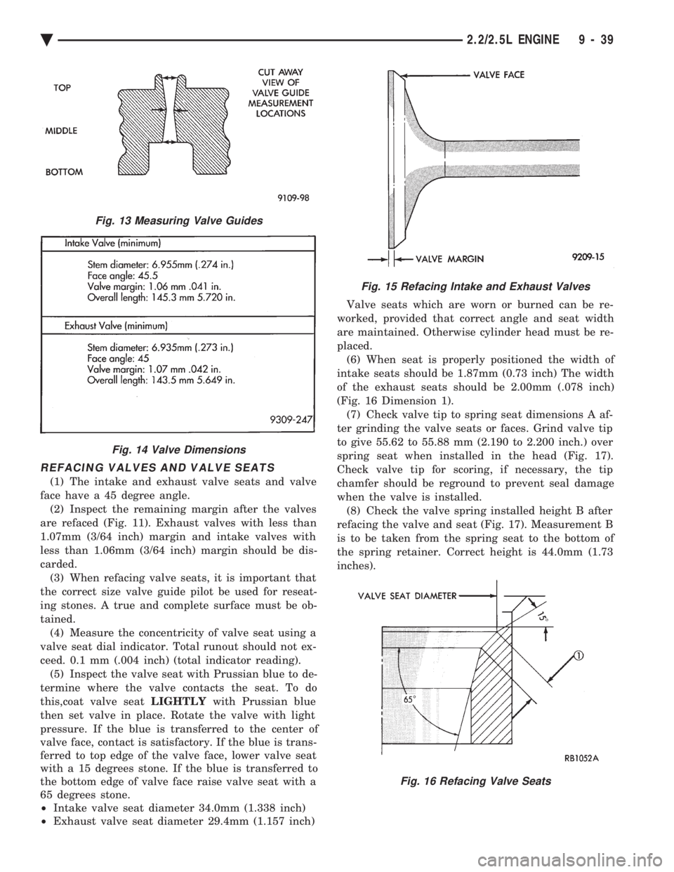
face have a 45 degree angle. (2) Inspect the remaining margin after the valves
are refaced (Fig. 11). Exhaust valves with less than
1.07mm (3/64 inch) margin and intake valves with
less than 1.06mm (3/64 inch) margin should be dis-
carded. (3) When refacing valve seats, it is important that
the correct size valve guide pilot be used for reseat-
ing stones. A true and complete surface must be ob-
tained. (4) Measure the concentricity of valve seat using a
valve seat dial indicator. Total runout should not ex-
ceed. 0.1 mm (.004 inch) (total indicator reading). (5) Inspect the valve seat with Prussian blue to de-
termine where the valve contacts the seat. To do
this,coat valve seat LIGHTLYwith Prussian blue
then set valve in place. Rotate the valve with light
pressure. If the blue is transferred to the center of
valve face, contact is satisfactory. If the blue is trans-
ferred to top edge of the valve face, lower valve seat
with a 15 degrees stone. If the blue is transferred to
the bottom edge of valve face raise valve seat with a
65 degrees stone.
² Intake valve seat diameter 34.0mm (1.338 inch)
² Exhaust valve seat diameter 29.4mm (1.157 inch) Valve seats which are worn or burned can be re-
worked, provided that correct angle and seat width
are maintained. Otherwise cylinder head must be re-
placed. (6) When seat is properly positioned the width of
intake seats should be 1.87mm (0.73 inch) The width
of the exhaust seats should be 2.00mm (.078 inch)
(Fig. 16 Dimension 1). (7) Check valve tip to spring seat dimensions A af-
ter grinding the valve seats or faces. Grind valve tip
to give 55.62 to 55.88 mm (2.190 to 2.200 inch.) over
spring seat when installed in the head (Fig. 17).
Check valve tip for scoring, if necessary, the tip
chamfer should be reground to prevent seal damage
when the valve is installed. (8) Check the valve spring installed height B after
refacing the valve and seat (Fig. 17). Measurement B
is to be taken from the spring seat to the bottom of
the spring retainer. Correct height is 44.0mm (1.73
inches).
Fig. 13 Measuring Valve Guides
Fig. 14 Valve Dimensions
Fig. 15 Refacing Intake and Exhaust Valves
Fig. 16 Refacing Valve Seats
Ä 2.2/2.5L ENGINE 9 - 39
Page 1653 of 2438
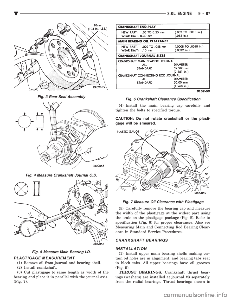
PLASTIGAGE MEASUREMENT
(1) Remove oil from journal and bearing shell.
(2) Install crankshaft.
(3) Cut plastigage to same length as width of the
bearing and place it in parallel with the journal axis.
(Fig. 7). (4) Install the main bearing cap carefully and
tighten the bolts to specified torque.
CAUTION: Do not rotate crankshaft or the plasti-
gage will be smeared.
(5) Carefully remove the bearing cap and measure
the width of the plastigage at the widest part using
the scale on the plastigage package (Fig. 8). Refer to
specification (Fig. 6) for proper clearances. Also see
Measuring Main and Connecting Rod Bearing Clear-
ance in Standard Service Procedures.
CRANKSHAFT BEARINGS
INSTALLATION
(1) Install upper main bearing shells making cer-
tain oil holes are in alignment, and bearing tabs seat
in block tabs. All upper bearings have oil grooves
(Fig. 9). THRUST BEARINGS. Crankshaft thrust bear-
ings (washers) are installed at journal #3 separately
from the radial bearings. Thrust bearings shown in
Fig. 3 Rear Seal Assembly
Fig. 4 Measure Crankshaft Journal O.D.
Fig. 5 Measure Main Bearing I.D.
Fig. 6 Crankshaft Clearance Specification
Fig. 7 Measure Oil Clearance with Plastigage
Ä 3.0L ENGINE 9 - 87
Page 1672 of 2438
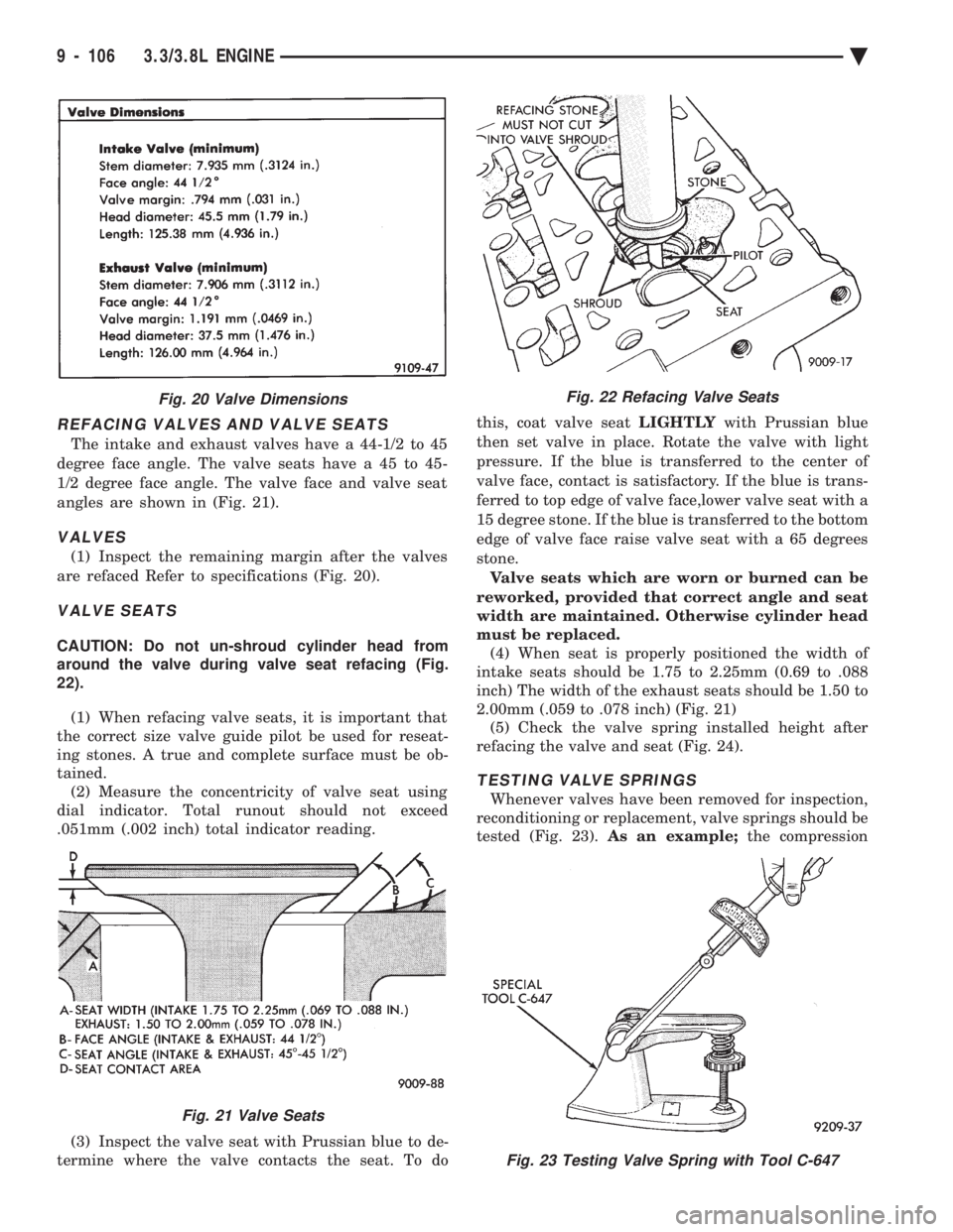
REFACING VALVES AND VALVE SEATS
The intake and exhaust valves have a 44-1/2 to 45
degree face angle. The valve seats have a 45 to 45-
1/2 degree face angle. The valve face and valve seat
angles are shown in (Fig. 21).
VALVES
(1) Inspect the remaining margin after the valves
are refaced Refer to specifications (Fig. 20).
VALVE SEATS
CAUTION: Do not un-shroud cylinder head from
around the valve during valve seat refacing (Fig.
22).
(1) When refacing valve seats, it is important that
the correct size valve guide pilot be used for reseat-
ing stones. A true and complete surface must be ob-
tained. (2) Measure the concentricity of valve seat using
dial indicator. Total runout should not exceed
.051mm (.002 inch) total indicator reading.
(3) Inspect the valve seat with Prussian blue to de-
termine where the valve contacts the seat. To do this, coat valve seat
LIGHTLYwith Prussian blue
then set valve in place. Rotate the valve with light
pressure. If the blue is transferred to the center of
valve face, contact is satisfactory. If the blue is trans-
ferred to top edge of valve face,lower valve seat with a
15 degree stone. If the blue is transferred to the bottom
edge of valve face raise valve seat with a 65 degrees
stone. Valve seats which are worn or burned can be
reworked, provided that correct angle and seat
width are maintained. Otherwise cylinder head
must be replaced. (4) When seat is properly positioned the width of
intake seats should be 1.75 to 2.25mm (0.69 to .088
inch) The width of the exhaust seats should be 1.50 to
2.00mm (.059 to .078 inch) (Fig. 21) (5) Check the valve spring installed height after
refacing the valve and seat (Fig. 24).
TESTING VALVE SPRINGS
Whenever valves have been removed for inspection,
reconditioning or replacement, valve springs should be
tested (Fig. 23). As an example; the compression
Fig. 23 Testing Valve Spring with Tool C-647
Fig. 20 Valve Dimensions
Fig. 21 Valve Seats
Fig. 22 Refacing Valve Seats
9 - 106 3.3/3.8L ENGINE Ä
Page 1686 of 2438
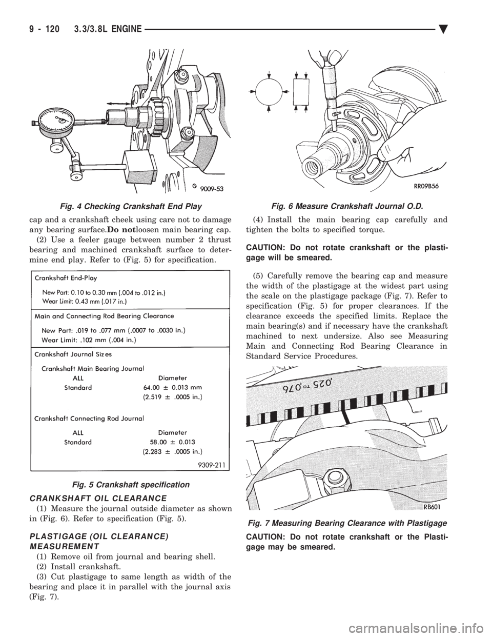
cap and a crankshaft cheek using care not to damage
any bearing surface. Do notloosen main bearing cap.
(2) Use a feeler gauge between number 2 thrust
bearing and machined crankshaft surface to deter-
mine end play. Refer to (Fig. 5) for specification.
CRANKSHAFT OIL CLEARANCE
(1) Measure the journal outside diameter as shown
in (Fig. 6). Refer to specification (Fig. 5).
PLASTIGAGE (OIL CLEARANCE) MEASUREMENT
(1) Remove oil from journal and bearing shell.
(2) Install crankshaft.
(3) Cut plastigage to same length as width of the
bearing and place it in parallel with the journal axis
(Fig. 7). (4) Install the main bearing cap carefully and
tighten the bolts to specified torque.
CAUTION: Do not rotate crankshaft or the plasti-
gage will be smeared.
(5) Carefully remove the bearing cap and measure
the width of the plastigage at the widest part using
the scale on the plastigage package (Fig. 7). Refer to
specification (Fig. 5) for proper clearances. If the
clearance exceeds the specified limits. Replace the
main bearing(s) and if necessary have the crankshaft
machined to next undersize. Also see Measuring
Main and Connecting Rod Bearing Clearance in
Standard Service Procedures.
CAUTION: Do not rotate crankshaft or the Plasti-
gage may be smeared.
Fig. 4 Checking Crankshaft End Play
Fig. 5 Crankshaft specification
Fig. 6 Measure Crankshaft Journal O.D.
Fig. 7 Measuring Bearing Clearance with Plastigage
9 - 120 3.3/3.8L ENGINE Ä