1993 CHEVROLET PLYMOUTH ACCLAIM warning light
[x] Cancel search: warning lightPage 605 of 2438
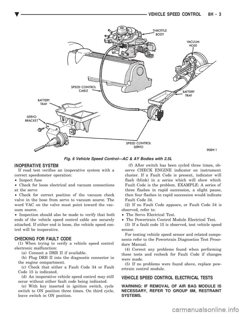
INOPERATIVE SYSTEM
If road test verifies an inoperative system with a
correct speedometer operation:
² Inspect fuse
² Check for loose electrical and vacuum connections
at the servo
² Check for correct position of the vacuum check
valve in the hose from servo to vacuum source. The
word VAC on the valve must point toward the vac-
uum source.
² Inspection should also be made to verify that both
ends of the vehicle speed control cable are securely
attached. If either end is loose, the vehicle speed con-
trol will be inoperative.
CHECKING FOR FAULT CODE
(1) When trying to verify a vehicle speed control
electronic malfunction: (a) Connect a DRB II if available.
(b) Plug DRB II into the diagnostic connector in
the engine compartment. (c) Check that either a Fault Code 34 or Fault
Code 15 is indicated. (d) An inoperative vehicle speed control may still
occur without either fault code being indicated. (e) With key inserted in ignition switch, cycle
switch to ON position three times. On third cycle,
leave switch in ON position. (f) After switch has been cycled three times, ob-
serve CHECK ENGINE indicator on instrument
cluster. If a Fault Code is present, indicator will
flash (blink) in a series which will show which
Fault Code is the problem. EXAMPLE: A series of
three flashes in rapid succession, a slight pause,
then four flashes in rapid succession would indicate
Fault Code 34.
(2) If no Fault Code appears, or Fault Code 34 is
observed, refer to:
² The Servo Electrical Test.
² The Powertrain Control Module Electrical Test.
(3) If a fault code 15 is observed, test vehicle speed
sensor. For testing vehicle speed sensor and related compo-
nents refer to the Powertrain Diagnostics Test Proce-
dure Manual. (4) Correct any problems found when performing
these tests and recheck for Fault Code if changes
were made. (5) If no problems were found above, replace pow-
ertrain control module.
VEHICLE SPEED CONTROL ELECTRICAL TESTS
WARNING: IF REMOVAL OF AIR BAG MODULE IS
NECESSARY, REFER TO GROUP 8M, RESTRAINT
SYSTEMS.
Fig. 6 Vehicle Speed ControlÐAC & AY Bodies with 2.5L
Ä VEHICLE SPEED CONTROL 8H - 3
Page 685 of 2438

SERVICE OF DEPLOYED AIR BAG MODULE
After an air bag has been deployed, the air bag
module and clockspring must be replaced because
they cannot be reused. Other air bag system compo-
nents are replaced if damaged.
SCHEDULED MAINTENANCE INSPECTION
Vehicles equipped with a Air Bag System must be
inspected every three years or 30,000 miles / 48,000
Km. The following items should be inspected. (1) Inspect components for damage or deteriora-
tion. (a) If the air bag module housing shows signs of
physical damage or abuse, replace the module. (b) Check that both front impact sensors are
properly installed to the upper crossmember of the
radiator closure panel. Repair as required.
(2) Check the air bag warning lamp for proper op-
eration as follows: (a) Turn ignition switch to the ON position, the
air bag warning lamp should light. If not, test the system using the DRB II and Passive Restraint
System Diagnostic Procedures Manual. Repair as
required.
(b) The air bag warning lamp lights, but fails to go
out after ten seconds. Test the system using the DRB
II and Passive Restraint System Diagnostic Proce-
dures Manual. Repair as required. (c) Erasing of fault codes is not required.
AIR BAG SYSTEM CHECK
WARNING: BEFORE BEGINNING ANY AIR BAG SYS-
TEM CHECK PROCEDURES, REMOVE AND ISOLATE
THE BATTERY NEGATIVE (-) CABLE (GROUND)
FROM THE VEHICLE BATTERY. THIS IS THE ONLY
SURE WAY TO DISABLE THE AIR BAG SYSTEM.
FAILURE TO DO THIS COULD RESULT IN ACCIDEN-
TAL AIR BAG DEPLOYMENT AND POSSIBLE PER-
SONAL INJURY.
WHEN AN UNDEPLOYED AIR BAG ASSEMBLY IS
TO BE REMOVED FROM THE STEERING WHEEL,
DISCONNECT BATTERY GROUND CABLE AND
ISOLATE. ALLOW SYSTEM CAPACITOR TO DIS-
CHARGE FOR TWO MINUTES, THEN BEGIN AIR
BAG REMOVAL. (1) Disconnect the battery negative cable and iso-
late. (2) Remove forward console or cover as necessary.
(3) Connect DRB II to ASDM diagnostic 6-way con-
nector, located at right side of module. (4) Turn the ignition key to ON position. Exit vehicle
with DRB II. Use the latest version of the proper
cartridge. (5) After checking that no one is inside the vehicle,
connect the negative battery cable. (6) Using the DRB II, read and record active fault
data. (7) Read and record any stored faults.
(8) Refer to the Passive Restraint Diagnostic Test
Manual if any faults are found in steps 6 and 7. (9) Erase stored faults if there are no active fault
codes. If problems remain, fault codes will not erase. (10) With the ignition key in the ON position, make
sure no one is in the vehicle. (11) From the passenger side of vehicle, turn the
ignition key to OFF then ON and observe the instru-
ment cluster air bag lamp. It should go on for 6 to 8
seconds, then go out; indicating system is functioning
normally. If air bag warning lamp either fails to light,
blinks on and off or goes on and stays on, there is
a system malfunction. Refer to the Passive Re-
straint Diagnostic Test Manual to diagnose the
problem.
Fig. 3 Seal the Air Bag Exhaust Vents
Fig. 4 Vacuum Heater and A/C Outlets
Ä RESTRAINT SYSTEMS 8M - 3
Page 731 of 2438
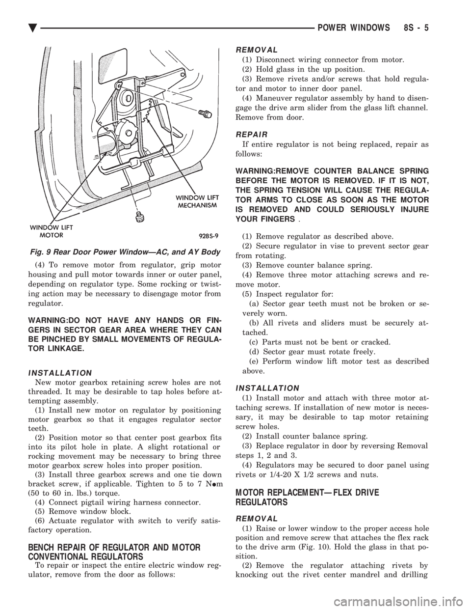
(4) To remove motor from regulator, grip motor
housing and pull motor towards inner or outer panel,
depending on regulator type. Some rocking or twist-
ing action may be necessary to disengage motor from
regulator.
WARNING:DO NOT HAVE ANY HANDS OR FIN-
GERS IN SECTOR GEAR AREA WHERE THEY CAN
BE PINCHED BY SMALL MOVEMENTS OF REGULA-
TOR LINKAGE.
INSTALLATION
New motor gearbox retaining screw holes are not
threaded. It may be desirable to tap holes before at-
tempting assembly. (1) Install new motor on regulator by positioning
motor gearbox so that it engages regulator sector
teeth. (2) Position motor so that center post gearbox fits
into its pilot hole in plate. A slight rotational or
rocking movement may be necessary to bring three
motor gearbox screw holes into proper position. (3) Install three gearbox screws and one tie down
bracket screw, if applicable. Tighten to 5 to 7 N Im
(50 to 60 in. lbs.) torque. (4) Connect pigtail wiring harness connector.
(5) Remove window block.
(6) Actuate regulator with switch to verify satis-
factory operation.
BENCH REPAIR OF REGULATOR AND MOTOR
CONVENTIONAL REGULATORS
To repair or inspect the entire electric window reg-
ulator, remove from the door as follows:
REMOVAL
(1) Disconnect wiring connector from motor.
(2) Hold glass in the up position.
(3) Remove rivets and/or screws that hold regula-
tor and motor to inner door panel. (4) Maneuver regulator assembly by hand to disen-
gage the drive arm slider from the glass lift channel.
Remove from door.
REPAIR
If entire regulator is not being replaced, repair as
follows:
WARNING:REMOVE COUNTER BALANCE SPRING
BEFORE THE MOTOR IS REMOVED. IF IT IS NOT,
THE SPRING TENSION WILL CAUSE THE REGULA-
TOR ARMS TO CLOSE AS SOON AS THE MOTOR
IS REMOVED AND COULD SERIOUSLY INJURE
YOUR FINGERS .
(1) Remove regulator as described above.
(2) Secure regulator in vise to prevent sector gear
from rotating. (3) Remove counter balance spring.
(4) Remove three motor attaching screws and re-
move motor. (5) Inspect regulator for:(a) Sector gear teeth must not be broken or se-
verely worn. (b) All rivets and sliders must be securely at-
tached. (c) Parts must not be bent or cracked.
(d) Sector gear must rotate freely.
(e) Perform window lift motor test as described
above.
INSTALLATION
(1) Install motor and attach with three motor at-
taching screws. If installation of new motor is neces-
sary, it may be desirable to tap motor retaining
screw holes. (2) Install counter balance spring.
(3) Replace regulator in door by reversing Removal
steps 1, 2 and 3. (4) Regulators may be secured to door panel using
rivets or 1/4-20 X 1/2 screws and nuts.
MOTOR REPLACEMENTÐFLEX DRIVE
REGULATORS
REMOVAL
(1) Raise or lower window to the proper access hole
position and remove screw that attaches the flex rack
to the drive arm (Fig. 10). Hold the glass in that po-
sition. (2) Remove the regulator attaching rivets by
knocking out the rivet center mandrel and drilling
Fig. 9 Rear Door Power WindowÐAC, and AY Body
Ä POWER WINDOWS 8S - 5
Page 745 of 2438
CHIME WARNING/REMINDER SYSTEM
CONTENTS
page page
BODY CONTROLLER REPLACEMENT ........ 5
CHIME MODULE REPLACEMENT AA and AP BODIES .............................. 5
CHIME SYSTEM DIAGNOSISÐAA AND AP BODIES .............................. 2
CHIME SYSTEM DIAGNOSISÐAC, AG, AJ AND AY BODIES ....................... 3
CHIME WARNING/REMINDER SYSTEM TEST . 1 GENERAL INFORMATION
.................. 1
HEADLAMP SWITCH REPLACEMENT ........ 5
KEY-IN SWITCH REPLACEMENT ............ 5
SEAT BELT BUCKLE REPLACEMENT ........ 5
SEAT BELT BUCKLE SWITCH TEST BUZZER SYSTEM .............................. 1
SERVICE PROCEDURES ................... 5
TIMED BUZZER-RELAY TESTÐAP BODY ..... 1
GENERAL INFORMATION
WARNING: ON VEHICLES EQUIPPED WITH AN AIR
BAG REFER TO THE AIR BAG PORTION OF THIS
SECTION FOR STEERING WHEEL OR SWITCH RE-
MOVAL AND INSTALLATION PROCEDURES.
BUZZER SYSTEM
The seat belt warning system uses both visual and
audible signals. A combined seat belt and key warn-
ing buzzer with a red light on the instrument panel. The system will always illuminate the seat belt
warning lamp for four to eight seconds when the ig-
nition switch is turned to the ON position. Also, only
if the driver does not fasten his seat belt, the buzzer
will sound during the same time interval. Passenger
belts are not connected to the system. A timed buzzer-relay is used to operate the system
for the time period. It consists of a time delay mech-
anism and buzzer assembly. Only the driver's seat
belt buckle has a switch that is connected to the sys-
tem.
CHIME WARNING/REMINDER SYSTEM
The chime warning/reminder system is similar in
operation to the buzzer system except for a more
pleasant sounding tone. This chime type tone sounds
for all three warning/reminder conditions; namely
headlamps left on, keys left in ignition and fasten
seat belt.
TIMED BUZZER-RELAY TESTÐAP BODY
PREPARATION
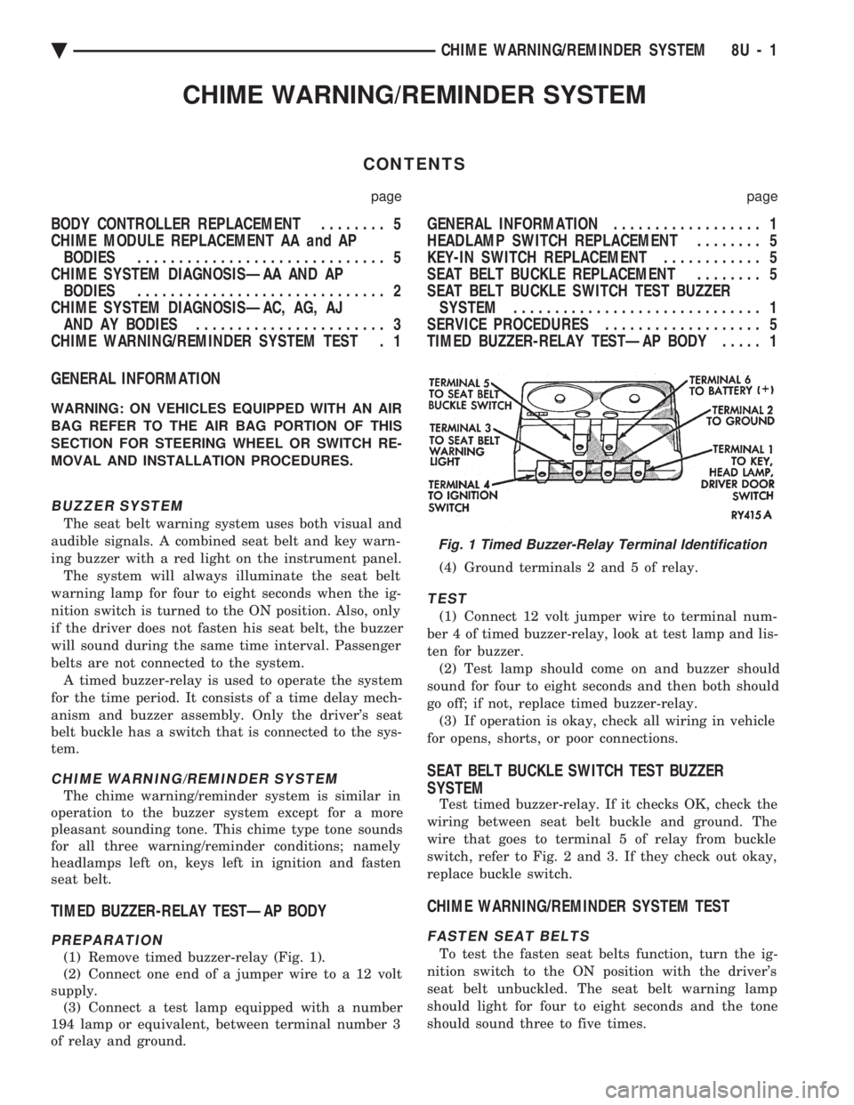
(1) Remove timed buzzer-relay (Fig. 1).
(2) Connect one end of a jumper wire to a 12 volt
supply. (3) Connect a test lamp equipped with a number
194 lamp or equivalent, between terminal number 3
of relay and ground. (4) Ground terminals 2 and 5 of relay.
TEST
(1) Connect 12 volt jumper wire to terminal num-
ber 4 of timed buzzer-relay, look at test lamp and lis-
ten for buzzer. (2) Test lamp should come on and buzzer should
sound for four to eight seconds and then both should
go off; if not, replace timed buzzer-relay. (3) If operation is okay, check all wiring in vehicle
for opens, shorts, or poor connections.
SEAT BELT BUCKLE SWITCH TEST BUZZER
SYSTEM
Test timed buzzer-relay. If it checks OK, check the
wiring between seat belt buckle and ground. The
wire that goes to terminal 5 of relay from buckle
switch, refer to Fig. 2 and 3. If they check out okay,
replace buckle switch.
CHIME WARNING/REMINDER SYSTEM TEST
FASTEN SEAT BELTS
To test the fasten seat belts function, turn the ig-
nition switch to the ON position with the driver's
seat belt unbuckled. The seat belt warning lamp
should light for four to eight seconds and the tone
should sound three to five times.
Fig. 1 Timed Buzzer-Relay Terminal Identification
Ä CHIME WARNING/REMINDER SYSTEM 8U - 1
Page 749 of 2438

CONDITION: NO TONE WHEN HEADLAMPS ARE ON AND DRIVER'S DOOR IS OPEN, ANDIGNITION IS OFF
PROCEDURE
(1) Check left door jamb switch for good ground
when driver's door is open. This may be checked at
terminal 1 of 25-way body controller connector. (2) Check for battery feed at terminal 16 of 25-way
body controller connector. (3) Check headlamp switch.
CONDITION: NO TONE WHEN KEY IS LEFT INIGNITION AND DRIVER'S DOOR IS OPEN
PROCEDURE
(1) Check left door jamb switch for good ground
when driver's door is open. This may be checked at
terminal 1 of 25-way body controller connector. (2) Check for battery feed at terminal 16 of 25-way
body controller connector. (3) Check key-in switch.
CONDITION: CHIMES CONTINUE WHENHEADLAMPS ARE TURNED OFF AND/OR KEYIS REMOVED FROM IGNITION
PROCEDURE
Check wiring for a grounded condition between
headlamp switch, key-in switch, and body controller.
SERVICE PROCEDURES
CHIME MODULE REPLACEMENT AA and AP
BODIES
(1) Open glove box door and disconnect check strap.
(2) Disconnect glove box light switch.
(3) Remove screws from glove box assembly and
remove. (4) Remove two screws from chime module mount-
ing bracket (Figs. 9 and 10). (5) Disconnect chime module wiring and remove
module. (6) For installation reverse above procedures.
BODY CONTROLLER REPLACEMENT
Refer to Group 8E, Instrument Panel and Gauges.
SEAT BELT BUCKLE REPLACEMENT
Refer to Group 23, Body of this service manual.
HEADLAMP SWITCH REPLACEMENT
Refer to Group 8E, Instrument Panel and Gauges.
KEY-IN SWITCH REPLACEMENT
The Key-in switch is built into the ignition switch as-
sembly. Should the Key-in switch require service, the
ignition switch assembly must be replaced. Refer to
Group 8D Ignition System of this service manual (Fig.
11).
Fig. 9 Chime Module LocationÐAA Body
Fig. 10 Chime Module Location
Fig. 11 Halo Lamp and Key-In Warning Switch Continuity
Ä CHIME WARNING/REMINDER SYSTEM 8U - 5
Page 931 of 2438
WIRING DIAGRAMS AA-BODY
INDEX
Wiring Diagram
Name Sheet Number
Airbag System ...............................47
Clockspring ...............................47
Diagnostic Module ..........................47
Interface Grommet ..........................47
Sensor-Left ...............................47
Sensor-Right ..............................47
Squibb ..................................47
Air Conditioning Compressor ...................32, 33
Air Conditioning System (2.5L Engine) ...............71
A/C Cycling Switch ..........................71
Blower Motor ..............................71
Blower Switch .............................71
Control Switch .............................71
Damped Pressure Switch ......................71
Defrost Switch .............................71
Illumination Lamp ...........................71
Resistor .................................71
Air Conditioning System (3.0L Engine) ...............72
A/C Switch ...............................72
Blower Motor ..............................72
Blower Switch .............................72
Control Switch .............................72
Damped Pressure Switch ......................72
Defrost Switch .............................72
High Pressure Switch ........................72
Illumination Lamp ...........................72
Resistor .................................72
Anti-Lock Brake System .................41, 42, 43, 44
ABS Pump Motor Relay .......................41
ABS System Relay ..........................43
ABS Warning Lamp Relay ......................43
Brake Switch ..............................44
Controller ....................... .41, 42, 43, 44
Hydraulic Modulator .........................41
Ignition Switch .............................44
Park Brake Switch ...........................44
Wheel Sensors .............................42
Ash Receiver Lamp ...........................52
Automatic Shut-down Relay .................14, 20, 28
Automatic Transmission Park/Neutral Position and Back-Up Lamp Switch ...............................9
Back-Up Lamp Switch ..........................9
Battery ............................1,5,7,39,40
Blower Motor-A/C ............................71
Blower Motor-Heater ...........................71
Brake Switch ...............................44
Brake Warning Lamp Switch ......................11
Bulkhead Disconnect (50-Way) ................112, 113
Center High Mounted Stop Lamp ..........94, 98, 102, 105
Charging System (2.5L) ........................5,6
Battery ...................................5
Generator .................................6Wiring Diagram
Name Sheet Number
Heated Rear Window Switch .....................5
Charging System (3.0L) ........................7,8
Battery ....................................7
Generator .................................8
Ignition Off-Draw Connector .....................7
Cigar Lighter ................................45
Cigar Lighter Lamp ............................52
Circuit Breaker (30 Amp) Fuseblock Cavity #10 .......67, 82
Circuit Breaker (30 Amp) Fuseblock Cavity #13 . . .2, 66, 67, 86
Clockspring ............................. .47, 59
Cluster Printed Circuit Board .................119, 120
Cluster Printed Circuit Board Connectors .............118
Courtesy Lamps .............................76
Daytime Running Light Module ....................57
Deck Lid Ajar Switch ..........................78
Dimmer Switch-Headlamp .....................1,50
Distributor ......................... .15, 21, 22, 27
EGR Solenoid ...............................24
Electrically Heated Rear Window ...................84
Heated Rear Window .........................84
Switch ..................................84
Timer ...................................84
Electronically Tuned Stereo Radio without Name Brand Speakers ................................87
Electronically Tuned Stereo Radio with Name Brand Speakers ................................89
Speaker Choke .............................89
Speaker Relay .............................89
Electronic Cluster ........................... .121
Engine Coolant Sensor ................... .15, 21, 27
Engine Oil and Temperature Warning System (2.5L) .......39
Engine Oil and Temperature Warning System (3.0L) .......40
Engine Oil Pressure Switch/Sending Unit ...........39, 40
Engine Temperature Sending Unit ................39, 40
Engine Starter System (2.5L Engine & 3.0L ATX) .......9,10
Automatic Transmission Park/Neutral Position Switch .....9
Backup Lamp Switch ..........................9
EMCC Solenoid .............................9
Engine Starter Relay ..........................9
Manual Transmission Back-Up Lamp Switch ...........9
Permanent Magnet Engine Starter Motor .............9
Engine Temperature Sending Unit ................39, 40
Exhaust Gas Recirculation Diagnostic Solenoid ........13, 24
Fan Control System with A/C and Heater System (2.5L) ....32
A/C Compressor ............................32
A/C Compressor Clutch Relay ...................32
A/C High Pressure Switch ......................32
Fan Control Relay ...........................32
Radiator Fan Motor ..........................32
Fan Control System with A/C and Heater System (3.0L) ....33
A/C Conditioning Compressor ...................33
A/C Compressor Clutch Relay ...................33
Ä WIRING DIAGRAMS AA-BODY 8W - 181
Page 933 of 2438
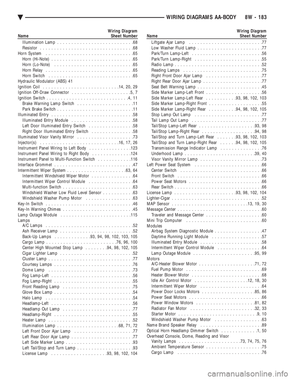
Wiring Diagram
Name Sheet Number
Illumination Lamp ...........................68
Resistor .................................68
Horn System ...............................65
Horn (Hi-Note) .............................65
Horn (Lo-Note) ............................65
Horn Relay ...............................65
Horn Switch ..............................65
Hydraulic Modulator (ABS) 41
Ignition Coil .......................... .14, 20, 29
Ignition Off-Draw Connector .....................5,7
Ignition Switch .............................4,11
Brake Warning Lamp Switch ....................11
Park Brake Switch ...........................11
Illuminated Entry .............................58
Illuminated Entry Module ......................58
Left Door Illuminated Entry Switch ................58
Right Door Illuminated Entry Switch ...............58
Illuminated Visor Vanity Mirror ....................73
Injector(s) ........................... .16, 17, 26
Instrument Panel Wiring to Left Body ...............123
Instrument Panel Wiring to Right Body ..............124
Instrument Panel to Multi-Function Switch ............116
Interface Grommet ............................47
Intermittent Wiper System .................... .63, 64
Intermittent Windshield Wiper Motor ...............64
Intermittent Wiper Control Module ................64
Multi-function Switch .........................63
Windshield Washer Low Fluid Level Sensor ...........63
Windshield Washer Pump Motor .................63
Key-In Switch ...............................46
Key-In Warning Chimes .........................45
Lamp Outage Module ........................ .115
Lamps A/C Lamps ...............................52
Ash Receiver Lamp ..........................52
Back-Up Lamps ............ .93, 94, 98, 102, 103, 105
Cargo Lamp ........................ .76, 96, 100
Center High Mounted Stop Lamp ........94, 98, 102, 105
Cigar Lighter Lamp ..........................52
Cluster Lamp ..............................77
Courtesy Lamps ............................76
Dome Lamp ..............................73
Fog Lamp-Left .............................56
Fog Lamp-Right ............................55
Front Reading Lamp .........................75
Glove Box Lamp ............................54
Halo Lamp ...............................54
Headlamp-Left .............................56
Headlamp Out Lamp .........................77
Headlamp-Right ............................55
Heater Lamp ..............................52
Illumination Lamp ..................... .68, 71, 72
Left Front Door Ajar Lamp .....................77
Left Rear Door Ajar Lamp ......................77
Left Side Marker Lamp ........................93
Left Tail/Stop and Turn Lamp ....................93
License Lamp ................... .93, 98, 102, 104Wiring Diagram
Name Sheet Number
Liftgate Ajar Lamp ..........................77
Low Washer Fluid Lamp .......................77
Park/Turn Lamp-Left .........................56
Park/Turn Lamp-Right ........................55
Radio Lamp ...............................52
Reading Lamps ............................75
Right Front Door Ajar Lamp ....................77
Right Rear Door Ajar Lamp .....................77
Seat Belt Warning Lamp .......................45
Side Marker Lamp-Left Front ....................56
Side Marker Lamp-Left Rear ...........93, 98, 102, 103
Side Marker Lamp-Right Front ...................55
Side Marker Lamp-Right Rear ..........94, 98, 102, 105
Stop Lamp Out Lamp ........................77
Tail Lamp Out Lamp .........................77
Tail/Stop Lamp-Left Rear ................... .93, 98
Tail/Stop Lamp-Right Rear .................. .94, 98
Tail/Stop and Turn Lamp-Left Rear .......93, 98, 102, 103
Tail/Stop and Turn Lamp-Right Rear ......94, 98, 102, 105
Transmission Range Indicator Lamp ...............76
Underhood Lamp ........................ .39, 40
Visor Vanity Mirror Lamp ......................73
Left Power Seat System ........................66
Center Switch .............................66
Front Switch ..............................66
Power Seat Motors ..........................66
Rear Switch ...............................66
License Lamp ..................... .93, 98, 102, 104
Lighter-Cigar ................................52
MAP Sensor .......................... .13, 19, 30
Message Center ..............................60
Traveler and Message Center ....................60
Mini Trip Computer ...........................60
Modules Airbag System Diagnostic Module .................47
Daytime Running Light Module ..................57
Illuminated Entry Module ......................58
Intermittent Wiper Control Module ................64
Lamp Outage Module ..................... .95, 99
Motors A/C-Heater Blower Motor ................... .71, 72
Fuel Pump Motor ...........................69
Heater Blower Motor .........................68
Idle Air Control Motor .................. .12, 18, 30
Intermittent Wiper Motor ......................64
Power Door Locks Motors .................. .85, 86
Power Seat Motors ..........................66
Power Window Motors .................... .81, 82
Radiator Fan Motor ...................... .32, 33
Starter Motor ............................9,10
Windshield Washer Pump Motor .................63
Name Brand Speaker Relay ......................89
Optical Horn Headlamp Dimmer Switch .............1,50
Overhead Console, Dome, Reading and Visor Vanity Lamps ..................... .73, 74, 75, 76
Ambient Temperature Sensor ....................75
Cargo Lamp ..............................76
Ä WIRING DIAGRAMS AA-BODY 8W - 183
Page 934 of 2438
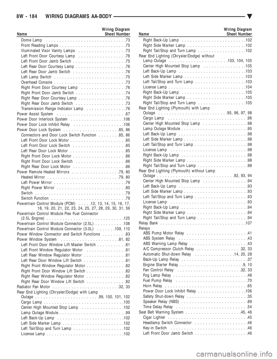
Wiring Diagram
Name Sheet Number
Dome Lamp ..............................73
Front Reading Lamps .........................75
Illuminated Visor Vanity Lamps ..................73
Left Front Door Courtesy Lamp ..................76
Left Front Door Jamb Switch ....................75
Left Rear Door Courtesy Lamp ...................76
Left Rear Door Jamb Switch ....................76
Left Lamp Switch ...........................75
Overhead Console ...........................73
Right Front Door Courtesy Lamp .................76
Right Front Door Jamb Switch ...................74
Right Rear Door Courtesy Lamp ..................76
Right Rear Door Jamb Switch ...................73
Transmission Range Indicator Lamp ...............76
Power Assist System ..........................67
Power Door Interlock System ....................106
Power Door Lock Inhibit Relay ...................106
Power Door Lock System .................... .85, 86
Connectors and Door Lock Switch Function ........85, 86
Left Front Door Lock Motor .....................85
Left Front Door Lock Switch ....................85
Left Rear Door Lock Motor .....................85
Right Front Door Lock Motor ....................86
Right Front Door Lock Switch ...................86
Right Rear Door Lock Motor ....................86
Power Remote Heated Mirrors ..................79, 80
Heated Mirror .......................... .79, 80
Left Power Mirror ...........................79
Right Power Mirror ..........................80
Switch ..................................79
Switch Function ............................79
Powertrain Control Module (PCM) .....12, 13, 14, 15, 16, 17,
18, 19, 20, 21, 22, 23, 24, 25, 27, 28, 29, 30, 31, 59
Powertrain Control Module Flex Fuel Connector (2.5L Engine) ............................ .125
Powertrain Control Module Connector (2.5L) ...........108
Powertrain Control Module Connector (3.0L) .......109, 110
Power Window Connector and Switch Functions .........83
Power Window System ..................... .81, 82
Left Front Door Window Lift Master Switch ...........81
Left Front Window Regulator Motor ...............81
Left Rear Window Regulator Motor ................81
Left Rear Door Window Lift Switch ................81
Right Front Window Regulator Motor ...............82
Right Front Door Window Lift Switch ...............82
Right Rear Window Regulator Motor ...............82
Right Rear Door Window Lift Switch ...............82
Radiator Fan Motor ........................ .32, 33
Rear End Lighting (Chrysler/Dodge) with Lamp Outage ....................... .99, 100, 101, 102
Cargo Lamp ............................. .100
Center High Mounted Stop Lamp ................102
Lamp Outage Module .........................99
Left Back-Up Lamp ........................ .102
Left Side Marker Lamp ...................... .102
Left Tail/Stop and Turn Lamp ...................102
License Lamp ............................ .102Wiring Diagram
Name Sheet Number
Right Back-Up Lamp ....................... .102
Right Side Marker Lamp ..................... .102
Right Tail/Stop and Turn Lamp ..................102
Rear End Lighting (Chrysler/Dodge) without Lamp Outage ..................... .103, 104, 105
Center High Mounted Stop Lamp ................105
Left Back-Up Lamp ........................ .103
Left Side Marker Lamp ...................... .103
Left Tail/Stop and Turn Lamp ...................103
License Lamp ............................ .104
Right Back-Up Lamp ....................... .105
Right Side Marker Lamp ..................... .105
Right Tail/Stop and Turn Lamp ..................105
Rear End Lighting (Plymouth) with Lamp Outage ......................... .95, 96, 97, 98
Cargo Lamp ..............................96
Center High Mounted Stop Lamp .................98
Lamp Outage Module .........................95
Left Back-Up Lamp ..........................98
Left Side Marker Lamp ........................98
Left Tail/Stop and Turn Lamp ....................98
License Lamp .............................98
Right Back-Up Lamp .........................98
Right Side Marker Lamp .......................98
Right Tail/Stop and Turn Lamp ...................98
Rear End Lighting (Plymouth) without Lamp Outage ............................ .92, 93, 94
Center High Mounted Stop Lamp .................94
Left Back-Up Lamp ..........................93
Left Side Marker Lamp ........................93
Left Tail/Stop and Turn Lamp ....................93
License Lamp .............................93
Right Back-Up Lamp .........................94
Right Side Marker Lamp .......................94
Right Tail/Stop and Turn Lamp ...................94
Relay Bank ............................... .107
Relays ABS Pump Motor Relay .......................41
ABS System Relay ..........................43
ABS Warning Lamp Relay ......................43
A/C Compressor Clutch Relay .................32, 33
Automatic Shut-down Relay ...............14, 20, 28
Back-Up Lamp Relay .........................37
Engine Starter Relay ........................9,10
Fan Control Relay ....................... .32, 33
Fog Lamp Relay ............................48
Fuel Pump Relay ...........................70
Horn Relay ...............................65
Power Door Lock Inhibit Relay ..................106
Safety Shut-down Relay .......................35
Speaker Relay (NBS) .........................89
Time Delay Relay ...........................54
Seat Belt Warning System .................... .45, 46
Cigar Lighter ..............................45
Headlamp Switch Connector ....................46
Key-in Switch .............................46
Left Front Door Jamb Switch ....................46
8W - 184 WIRING DIAGRAMS AA-BODY Ä