1993 CHEVROLET PLYMOUTH ACCLAIM warning light
[x] Cancel search: warning lightPage 534 of 2438
AG AND AJ BODIES INDEX
page page
Cigar Lighter Removal ..................... 55
Cluster and Gauge Service and Testing ....... 43
Electronic Cluster ........................ 50
Electronic Vehicle Information Center (EVIC) .... 42
Engine Compartment Node ................. 55
Gauges ................................ 44 General Information
....................... 42
Instrument Panel Roll Down Procedure ........ 56
Interior Lamp Removal .................... 57
Mechanical/Electronic Cluster Removal ........ 43
Switch and Panel Component Service ......... 51
Switch Pod Assembly Removal .............. 43
GENERAL INFORMATION
CONVENTIONAL INSTRUMENT CLUSTER
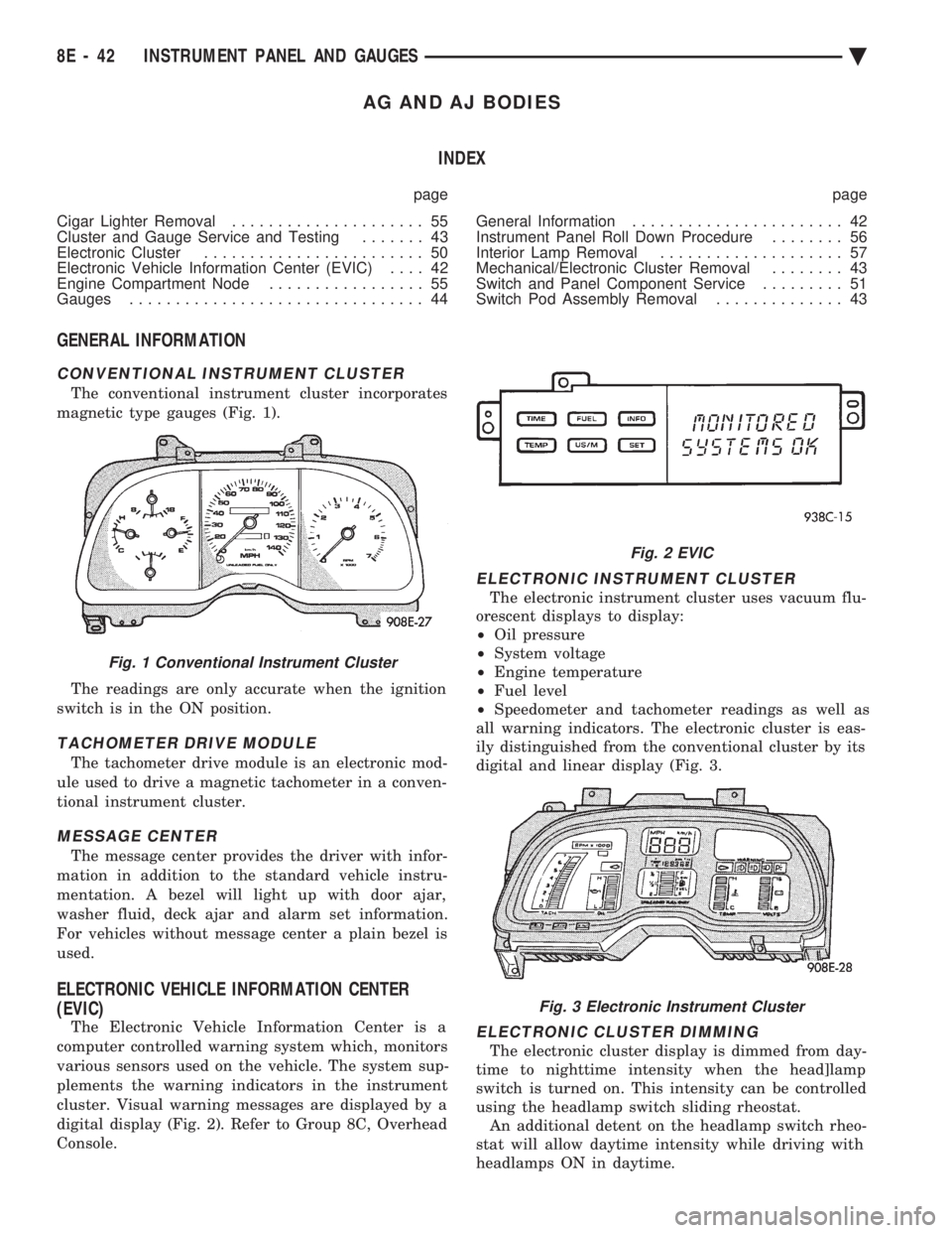
The conventional instrument cluster incorporates
magnetic type gauges (Fig. 1).
The readings are only accurate when the ignition
switch is in the ON position.
TACHOMETER DRIVE MODULE
The tachometer drive module is an electronic mod-
ule used to drive a magnetic tachometer in a conven-
tional instrument cluster.
MESSAGE CENTER
The message center provides the driver with infor-
mation in addition to the standard vehicle instru-
mentation. A bezel will light up with door ajar,
washer fluid, deck ajar and alarm set information.
For vehicles without message center a plain bezel is
used.
ELECTRONIC VEHICLE INFORMATION CENTER
(EVIC)
The Electronic Vehicle Information Center is a
computer controlled warning system which, monitors
various sensors used on the vehicle. The system sup-
plements the warning indicators in the instrument
cluster. Visual warning messages are displayed by a
digital display (Fig. 2). Refer to Group 8C, Overhead
Console.
ELECTRONIC INSTRUMENT CLUSTER
The electronic instrument cluster uses vacuum flu-
orescent displays to display:
² Oil pressure
² System voltage
² Engine temperature
² Fuel level
² Speedometer and tachometer readings as well as
all warning indicators. The electronic cluster is eas-
ily distinguished from the conventional cluster by its
digital and linear display (Fig. 3.
ELECTRONIC CLUSTER DIMMING
The electronic cluster display is dimmed from day-
time to nighttime intensity when the head]lamp
switch is turned on. This intensity can be controlled
using the headlamp switch sliding rheostat. An additional detent on the headlamp switch rheo-
stat will allow daytime intensity while driving with
headlamps ON in daytime.
Fig. 1 Conventional Instrument Cluster
Fig. 2 EVIC
Fig. 3 Electronic Instrument Cluster
8E - 42 INSTRUMENT PANEL AND GAUGES Ä
Page 535 of 2438

ELECTRONIC DIGITAL CLOCK
The electronic digital clock is in the radio. The
clock and radio each use the display panel built into
the radio. A digital readout indicates the time in
hours and minutes whenever the ignition switch is in
the ON or ACC position. When the ignition switch is in the ON or OFF po-
sition, or when the radio frequency is being dis-
played, time keeping is accurately maintained. The procedure for setting the clock varies slightly
with each radio. The correct procedure is described
under the individual radio operating instructions re-
ferred to in the Owner's manual supplied with the
vehicle.
WARNING LAMPS
The AG & AJ Body instrument clusters have warn-
ing lamps or indicators with the electronic cluster for
six different systems. These include low oil pressure,
check gauges, brake system, air bag, seat belt, mal-
function indicator (check engine) lamp.
CLUSTER AND GAUGE SERVICE AND TESTING
CAUTION: Disconnect negative battery cable, in en-
gine compartment, before servicing instrument
panel. When power is required for test purposes,
reconnect battery cable for test only. Disconnect negative battery cable after test and be-
fore continuing service procedures. It is not necessary to remove instrument cluster
from vehicle for gauge replacement. Gauges must be pulled straight out, when remov-
ing or pins may be damaged.
SWITCH POD ASSEMBLY REMOVAL
(1) Disconnect negative battery cable.
(2) Pry up edge of panel vent grille, using a
straight flat edge tool to disengage clips, then re-
move grille (Fig. 4). (3) Remove two screws located under panel vent
grille. (4) Remove two screws underneath switch POD as-
sembly. (5) With tilt steering adjust steering wheel to the
lowest setting. (6) Pull switch module rearward to remove module
and disconnect all wire connections. (7) For Installation reverse above procedures.
Tighten all screws to 2 N Im (20 in. lbs.) torque.
MECHANICAL/ELECTRONIC CLUSTER REMOVAL
CLUSTER MASK AND LENS REMOVAL
(1) Remove switch pod assembly (Fig. 4).
(2) Remove tilt column lever if equipped.
(3) Remove steering column trim cover.
Fig. 4 Switch POD Assembly
Ä INSTRUMENT PANEL AND GAUGES 8E - 43
Page 539 of 2438
(3) With the ignition switch ON, an open (discon-
nected sending unit wire) causes the oil, fuel or tem-
perature gauge to read below low, empty or cold
indicators. (4) If steps 2 and 3 check OK, refer to the individ-
ual sending unit test procedures.
FUEL TANK SENDING UNIT TEST
Refer to Group 14, Fuel for test procedure.
CHECK GAUGES WARNING LAMP TESTS
The check gauges warning lamp will illuminated
when the ignition key is turned to the ON position.
The lamp will illuminate if the engine oil pressure
drops below a safe level. The check gauge lamp will
light for high engine temperature or for low voltage. To test the system turn ignition key to the ON po-
sition. If the lamp fails to light, inspect for a broken
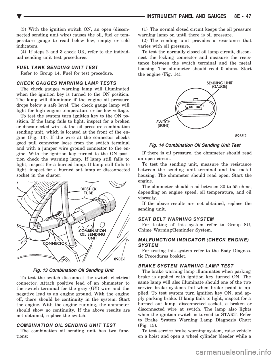
or disconnected wire at the oil pressure combination
sending unit, which is located at the front of the en-
gine (Fig. 13). If the wire at the connector checks
good pull connector loose from the switch terminal
and with a jumper wire ground connector to the en-
gine. With the ignition key turned to the ON posi-
tion check the warning lamp. If lamp still fails to
light, inspect for a burned lamp. If lamp still fails to
light, inspect for a burned out lamp or disconnected
socket in the cluster.
To test the switch disconnect the switch electrical
connector. Attach positive lead of an ohmmeter to
the switch terminal for the gray (GY) wire and the
negative lead to an engine ground. With the engine
off, there should be continuity in the system. Start
the engine. With the engine running, the ohmmeter
should show no continuity. If the above results are
not obtained, replace the switch.
COMBINATION OIL SENDING UNIT TEST
The combination oil sending unit has two func-
tions: (1) The normal closed circuit keeps the oil pressure
warning lamp on until there is oil pressure. (2) The sending unit provides a resistance that
varies with oil pressure. To test the normally closed oil lamp circuit, discon-
nect the locking connector and measure the resis-
tance between the switch terminal and the metal
housing. The ohmmeter should read 0 ohms. Start
the engine (Fig. 14).
If there is oil pressure, the ohmmeter should read
an open circuit. To test the sending unit, measure the resistance
between the sending unit terminal and the metal
housing. The ohmmeter should read open. Start the
engine. The ohmmeter should read between 30 to 55 ohms,
depending on engine speed, oil temperature, and oil
viscosity. If the above results are not obtained, replace the
sending unit.
SEAT BELT WARNING SYSTEM
For testing of this system refer to Group 8U,
Chime Warning/Reminder System.
MALFUNCTION INDICATOR (CHECK ENGINE) SYSTEM
For testing this system refer to the Body Diagnos-
tic Procedures booklet.
BRAKE SYSTEM WARNING LAMP TEST
The brake warning lamp illuminates when parking
brake is applied with ignition key turned ON. The
same lamp will also illuminate should one of the two
service brake systems fail when brake pedal is ap-
plied. To test system turn ignition key ON, and ap-
ply parking brake. If lamp fails to light, inspect for a
burned out lamp, disconnected socket, a broken or
disconnected wire at switch. The lamp also lights
when the ignition switch is turned to START. Refer
to Brake System Warning Lamp Diagnosis Chart
(Fig. 15). To test service brake warning system, raise vehicle
on a hoist and open a wheel cylinder bleeder while aFig. 13 Combination Oil Sending Unit
Fig. 14 Combination Oil Sending Unit Test
Ä INSTRUMENT PANEL AND GAUGES 8E - 47
Page 540 of 2438
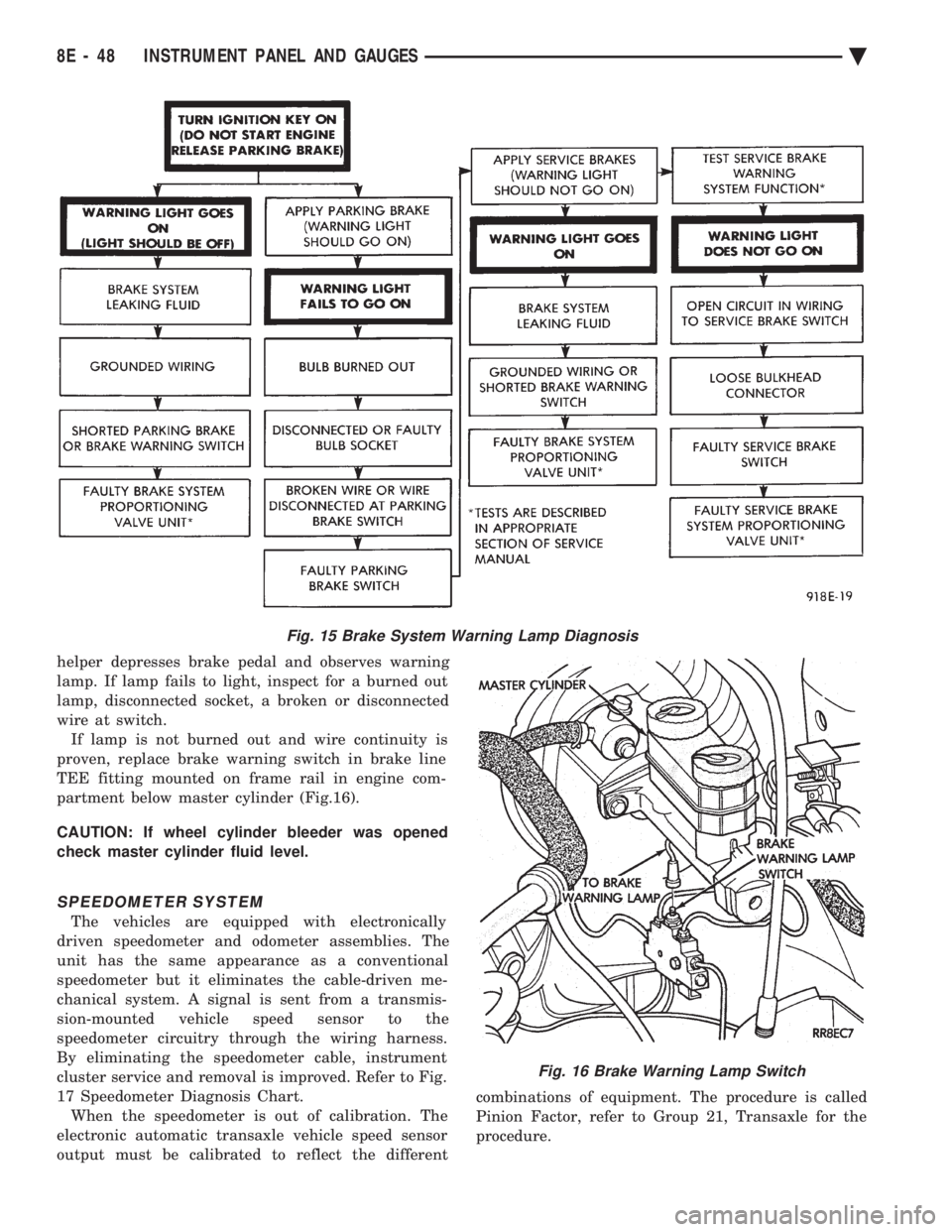
helper depresses brake pedal and observes warning
lamp. If lamp fails to light, inspect for a burned out
lamp, disconnected socket, a broken or disconnected
wire at switch.If lamp is not burned out and wire continuity is
proven, replace brake warning switch in brake line
TEE fitting mounted on frame rail in engine com-
partment below master cylinder (Fig.16).
CAUTION: If wheel cylinder bleeder was opened
check master cylinder fluid level.
SPEEDOMETER SYSTEM
The vehicles are equipped with electronically
driven speedometer and odometer assemblies. The
unit has the same appearance as a conventional
speedometer but it eliminates the cable-driven me-
chanical system. A signal is sent from a transmis-
sion-mounted vehicle speed sensor to the
speedometer circuitry through the wiring harness.
By eliminating the speedometer cable, instrument
cluster service and removal is improved. Refer to Fig.
17 Speedometer Diagnosis Chart. When the speedometer is out of calibration. The
electronic automatic transaxle vehicle speed sensor
output must be calibrated to reflect the different combinations of equipment. The procedure is called
Pinion Factor, refer to Group 21, Transaxle for the
procedure.
Fig. 15 Brake System Warning Lamp Diagnosis
Fig. 16 Brake Warning Lamp Switch
8E - 48 INSTRUMENT PANEL AND GAUGES Ä
Page 547 of 2438
AUTOMATIC TEMPERATURE CONTROL LAMP REMOVAL
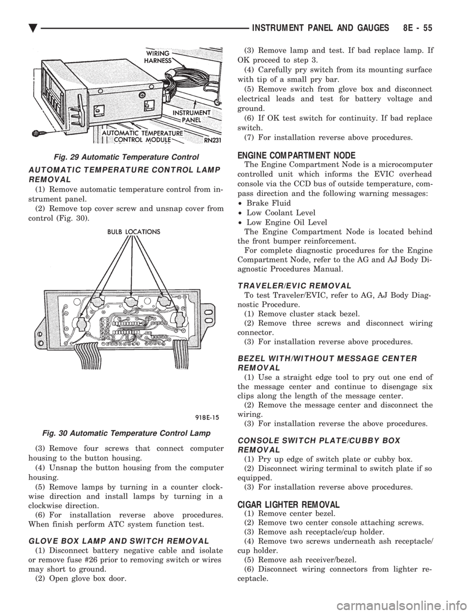
(1) Remove automatic temperature control from in-
strument panel. (2) Remove top cover screw and unsnap cover from
control (Fig. 30).
(3) Remove four screws that connect computer
housing to the button housing. (4) Unsnap the button housing from the computer
housing. (5) Remove lamps by turning in a counter clock-
wise direction and install lamps by turning in a
clockwise direction. (6) For installation reverse above procedures.
When finish perform ATC system function test.
GLOVE BOX LAMP AND SWITCH REMOVAL
(1) Disconnect battery negative cable and isolate
or remove fuse #26 prior to removing switch or wires
may short to ground. (2) Open glove box door. (3) Remove lamp and test. If bad replace lamp. If
OK proceed to step 3. (4) Carefully pry switch from its mounting surface
with tip of a small pry bar. (5) Remove switch from glove box and disconnect
electrical leads and test for battery voltage and
ground. (6) If OK test switch for continuity. If bad replace
switch. (7) For installation reverse above procedures.
ENGINE COMPARTMENT NODE
The Engine Compartment Node is a microcomputer
controlled unit which informs the EVIC overhead
console via the CCD bus of outside temperature, com-
pass direction and the following warning messages:
² Brake Fluid
² Low Coolant Level
² Low Engine Oil Level
The Engine Compartment Node is located behind
the front bumper reinforcement. For complete diagnostic procedures for the Engine
Compartment Node, refer to the AG and AJ Body Di-
agnostic Procedures Manual.
TRAVELER/EVIC REMOVAL
To test Traveler/EVIC, refer to AG, AJ Body Diag-
nostic Procedure. (1) Remove cluster stack bezel.
(2) Remove three screws and disconnect wiring
connector. (3) For installation reverse above procedures.
BEZEL WITH/WITHOUT MESSAGE CENTERREMOVAL
(1) Use a straight edge tool to pry out one end of
the message center and continue to disengage six
clips along the length of the message center. (2) Remove the message center and disconnect the
wiring. (3) For installation reverse the above procedures.
CONSOLE SWITCH PLATE/CUBBY BOXREMOVAL
(1) Pry up edge of switch plate or cubby box.
(2) Disconnect wiring terminal to switch plate if so
equipped. (3) For installation reverse above procedures.
CIGAR LIGHTER REMOVAL
(1) Remove center bezel.
(2) Remove two center console attaching screws.
(3) Remove ash receptacle/cup holder.
(4) Remove two screws underneath ash receptacle/
cup holder. (5) Remove ash receiver/bezel.
(6) Disconnect wiring connectors from lighter re-
ceptacle.
Fig. 29 Automatic Temperature Control
Fig. 30 Automatic Temperature Control Lamp
Ä INSTRUMENT PANEL AND GAUGES 8E - 55
Page 550 of 2438

AP BODY INDEX
page page
Cluster and Gauge Service and Testing ....... 58
Gauges ................................ 61
General Information ....................... 58 Instrument Panel Replacement
.............. 72
Interior Lamp Replacement ................. 73
Switch and Panel Component Service ......... 67
GENERAL INFORMATION
INSTRUMENT CLUSTER
There are two conventional instrument cluster as-
semblies available. The clusters incorporates mag-
netic type gauges and an electronically driven
speedometer and odometer assembly (Fig. 1 and 2).
MAGNETIC GAUGES
All gauges on the AP Body clusters are the mag-
netic type gauges. When the ignition switch is in the
OFF position each gauge, except for the voltmeter
and tachometer will show a reading. However, the
readings are only accurate when the ignition switch
is in the ON position.
TACHOMETER DRIVE MODULE
The tachometer drive module is an electronic mod-
ule used to drive the magnetic tachometer in the
high line cluster. This module is located on top of the instrument
cluster.
ELECTRONIC DIGITAL CLOCK
The electronic digital clock is in the radio. The
clock and radio each use the display panel built into
the radio. A digital readout indicates the time in
hours and minutes whenever the ignition switch is in
the ON or ACC position. When the ignition switch is in the OFF position, or
when the radio frequency is being displayed, time
keeping is accurately maintained. The procedure for setting the clock varies slightly
with each radio. The correct procedure is described
under the individual radio operating instructions re-
fer to the Sound Systems Manual supplied with the
vehicle.
WARNING LAMPS AND INDICATOR LIGHTS
The instrument cluster has warning and indicators
lamps for eight different systems:
² Low oil pressure
² Brake warning
² Seat belt warning
² Malfunction indicator (check engine) lamp
² Air Bag
² High beam indicator
² Right and left turn signals.
² Anti-lock (ABS)
CLUSTER AND GAUGE SERVICE AND TESTING
CAUTION: Disconnect the negative battery cable
before servicing the instrument panel. When power
is required for test purposes, reconnect battery ca-
ble for test only. Disconnect the negative battery
cable after test and before continuing service pro-
cedures.
SENDING UNIT TEST
Check for a defective sending unit or wiring, when
a problem occurs with a cluster gauge. Do this before
disassembling the cluster. (1) Sending units and wiring can be checked by
grounding the connector leads, at the sending unit,
in the vehicle. (2) With the ignition in the ON position, a
grounded input will cause the fuel or temperature
gauge to read at or above maximum.
Fig. 1 Instrument Cluster With Tachometer
Fig. 2 Instrument Cluster Without Tachometer
8E - 58 INSTRUMENT PANEL AND GAUGES Ä
Page 551 of 2438

FUEL TANK SENDING UNIT TEST
Refer to Group 14, Fuel for test procedures.
LOW OIL PRESSURE WARNING LAMP TEST
The low oil pressure warning lamp will illuminate
when the ignition key is turned to the ON position
without engine running. The lamp also illuminates
should the engine oil pressure drop below a safe oil
pressure level. To test the system turn ignition key to the ON po-
sition. If the lamp fails to light, inspect for a broken
or disconnected wire at the oil pressure combination
unit, located at the front of the engine (Fig. 3). If the
wire at the connector checks good, pull connector
loose from the switch and with a jumper wire ground
connector to the engine. With the ignition key turned
to the ON position check the warning lamp. If lamp
still fails to light, inspect for a burned out lamp or
disconnected socket in the cluster.
COMBINATION OIL SENDING UNIT TEST
The combination oil sending unit has two func-
tions: (1) The normal closed circuit keeps the oil pressure
warning lamp on until there is oil pressure (Fig. 4).
(2) The sending unit provides a resistance that
varies with oil pressure. To test the normally closed oil lamp circuit, discon-
nect the locking connector and measure the resis-
tance between the switch terminal and the metal
housing. The ohmmeter should read continuity. Start
the engine. If there is oil pressure, the ohmmeter should read
an open circuit. To test the sending unit, measure the resistance
between the sending unit terminal and the metal
housing. The ohmmeter should no continuity. Start
the engine. The ohmmeter should read between 30 to 55 ohms,
depending on engine speed, oil temperature and oil
viscosity. If the above results are not obtained, replace the
sending unit.
SEAT BELT WARNING SYSTEM
For testing of this system refer to Group 8M, Re-
straint Systems.
AIR BAG WARNING SYSTEM
For testing of this system refer to Group 8M, Re-
straint Systems.
MALFUNCTION INDICATOR (CHECK ENGINE) SYSTEM
For testing of this system using DRB II, refer to
the Body Powertrain Diagnostic Procedures.
BRAKE SYSTEM WARNING LAMP TEST
The brake warning lamp illuminates when parking
brake is applied with ignition key turned ON. The
same lamp will also illuminate should one of the two
service brake systems fail when brake pedal is ap-
plied. Refer to Brake system warning Lamp Diagno-
sis (Fig. 5). To test system turn ignition key ON and apply
parking brake. If lamp fails to light, inspect for a
burned out lamp, disconnected socket, a broken or
disconnected wire at switch. The lamp also lights
when the ignition switch is turned to start. To test service brake warning system, raise vehicle
on a hoist and open a wheel cylinder bleeder while a
helper depresses brake pedal and observes warning
lamp. If lamp fails to light, inspect for a burned out
lamp, disconnected socket, a broken or disconnected
wire at switch. If lamp is not burned out and wire continuity is
proven, replace brake warning switch in brake line
Tee fitting mounted on frame rail in engine compart-
ment below master cylinder (Fig. 6).
CAUTION: If wheel cylinder bleeder was opened
check master cylinder fluid level.
Fig. 3 Combination Oil Sending Unit
Fig. 4 Combination Oil Sending Unit Test
Ä INSTRUMENT PANEL AND GAUGES 8E - 59
Page 597 of 2438
HORNS
CONTENTS
page page
GENERAL INFORMATION .................. 1
HORN SWITCH REPLACEMENT ............ 3 TESTING HORN SYSTEM
................. 1
GENERAL INFORMATION
WARNING: ON VEHICLES EQUIPPED WITH AIR
BAG, SEE GROUP 8M, RESTRAINT SYSTEMS FOR
STEERING WHEEL OR COLUMN REMOVAL PROCE-
DURES.
The horn circuit consists of a horn switch, horn re-
lay, and horns. The horn circuit feed is from the fuse
box to the number 1 terminal on the horn relay.
When the horn switch is depressed, this completes
the circuit to ground. This activates the horn relay
and an set of contacts in the relay to close, which al-
lows current to flow to the horn(s). The horn ground
wire is attached to the headlamp ground screw (Fig.
1).
TESTING HORN SYSTEM
HORNS WILL NOT SOUND
If the horns do not sound, check for a blown horn
fuse in the fuse block. If the fuse is blown, replace it
with the same fuse type. If the horns fail to sound
and the new fuse blows when depressing the horn
switch, a short circuit in the horn or the horn wiring
between the fuse terminal and the horn is responsi-
ble. If the fuse is good, disconnect wire connector at
horn. Using an test lamp, connect one lead to the
negative terminal and the other to the positive ter-
minal (Fig. 2). Depress the horn switch, the test
lamp should illuminate. If not connect the test lamp wire to a good ground and depress the horn switch. If
test lamp lights inspect ground wire circuit and re-
pair as needed.
If the test lamp fails to illuminate, check for a de-
fective horn relay. Substituting a known good horn
relay in the circuit. If the test lamp illuminates
when depressing the horn switch, the original relay
is defective. If the test lamp fails to illuminate with
a known good relay, unplug that relay. Connect a
jumper wire from the battery terminal to the horn
terminal on the relay terminal board (Fig. 3, 4, or 5).
If the test lamp connected in place of the horns, fails
to illuminate an open circuit in the wiring between
the relay terminal and the horn switch is at fault re-
pair as necessary.
HORNS SOUND CONTINUOUSLY
CAUTION: Continuous sounding of horns may
cause relay to fail.
Should the horns sound continuously, unplug the
horn relay from the terminal board inside the pas-
senger compartment. Plug in a known good relay. If
the horns stop blowing, relay is defective and must
be replaced. Should the horns still sound, proceed as
follows: Connect one voltmeter lead to battery termi-
nal on relay board and the other lead to switch ter-
minal. Refer to Figs. 6, 7, or 8. Voltmeter will
Fig. 1 Conventional Horn System
Fig. 2 Horn and Connector
Ä HORNS 8G - 1