1993 CHEVROLET PLYMOUTH ACCLAIM parking brake
[x] Cancel search: parking brakePage 2006 of 2438
so that pump housing and case front may be covered
with soapy solution or water. Leaks are sometimes
caused by porosity in the case or pump housing.If a leak source is located, that part and all associ-
ated seals, O-rings, and gaskets should be replaced
with new parts.
GEARSHIFT LINKAGE ADJUSTMENT
Normal operation of the Park/Neutral Position
Switch provides a quick check to confirm proper
manual linkage adjustment. Move the selector level slowly upward until it
clicks into the ``P'' Park notch in the selector gate. If
the starter will operate the ``P'' position is correct. After checking ``P'' position, move selector slowly
toward ``N'' Neutral position until lever drops in the
``N'' stop. If the starter will also operate at this point
the gearshift linkage is properly adjusted. If the
starter fails to operate in either position, linkage ad-
justment is required.
CAUTION: When it is necessary to disassemble
linkage cable from levers, which use plastic grom-
mets as retainers, the grommets should be replaced
with new grommets. Use a prying tool to force rod
from grommet in lever, then cut away old grommet.
Use pliers to snap new grommet into lever and rod
into grommet.
(1) Set parking brake.
(2) Place gearshift lever in P(PARK) position.
(3) Loosen clamp bolt on gearshift cable bracket.
(4) Column shift: Insure that preload adjustment
spring engages fork on transaxle bracket. (5) Pull the shift lever by hand to the front detent
position (PARK) and tighten lock. Tighten screw to
11 N Im (100 in. lbs.). Gearshift linkage should now
be properly adjusted. (6) Check adjustment as follows:(a) Detent position for neutral and drive should
be within limits of hand lever gate stops. (b) Key start must occur only when shift lever is
in park or neutral positions.
THROTTLE PRESSURE LINKAGE ADJUSTMENT
The throttle pressure cable adjustment is very im-
portant to proper transaxle operation. This adjust-
ment positions a valve which controls shift speed,
shift quality, and part throttle downshift sensitivity.
If the setting is too long, early shifts and slippage be-
tween shifts may occur. If the setting is too short,
shifts may be delayed and part throttle downshifts
may be very sensitive.
CABLE ADJUSTMENT PROCEDURE (4-CYL.)
(1) Perform transaxle throttle pressure cable ad-
justment while engine is at normal operating tem-
perature. (2) Loosen cable mounting bracket lock screw.
(3) Bracket should be positioned with both bracket
alignment tabs touching the transaxle cast surface.
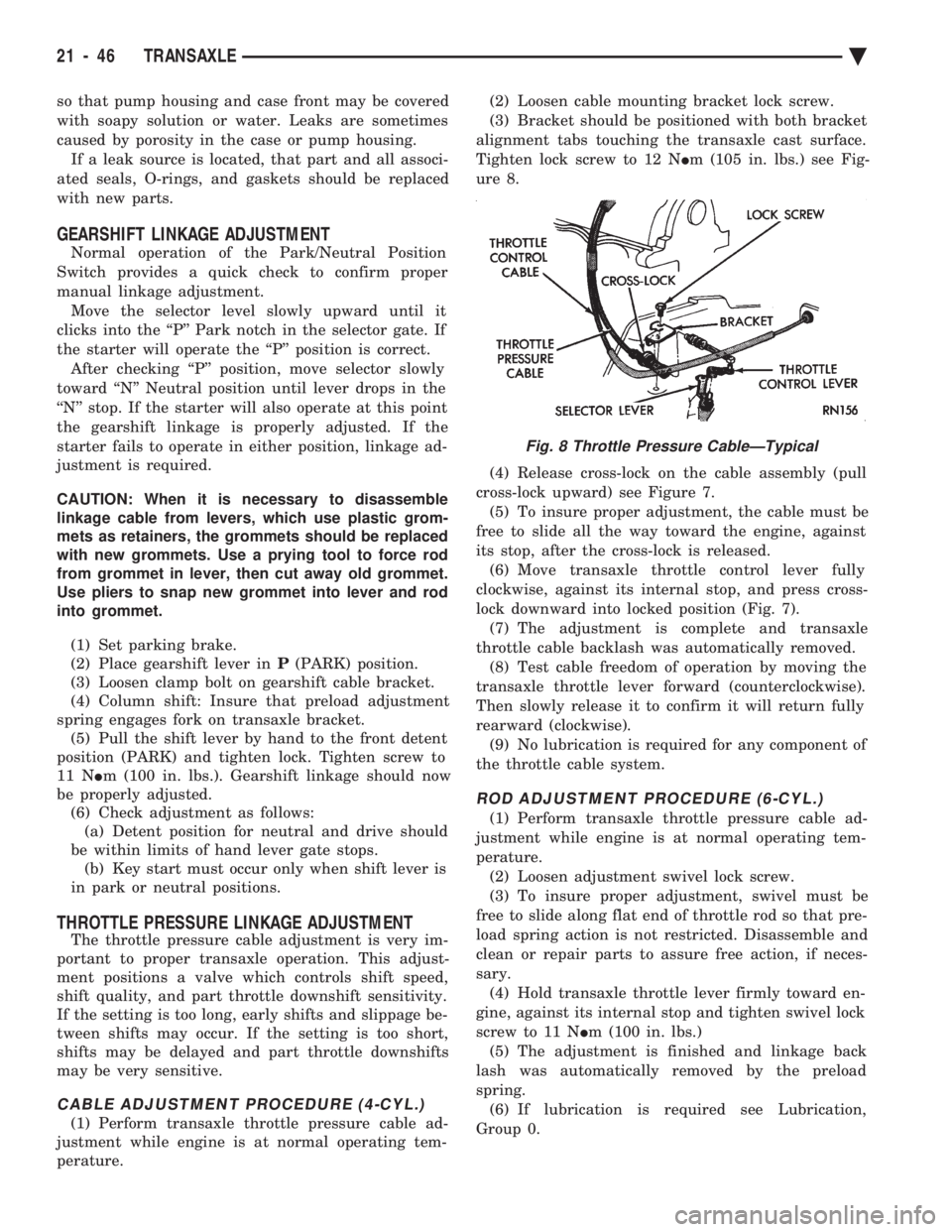
Tighten lock screw to 12 N Im (105 in. lbs.) see Fig-
ure 8.
(4) Release cross-lock on the cable assembly (pull
cross-lock upward) see Figure 7. (5) To insure proper adjustment, the cable must be
free to slide all the way toward the engine, against
its stop, after the cross-lock is released. (6) Move transaxle throttle control lever fully
clockwise, against its internal stop, and press cross-
lock downward into locked position (Fig. 7). (7) The adjustment is complete and transaxle
throttle cable backlash was automatically removed. (8) Test cable freedom of operation by moving the
transaxle throttle lever forward (counterclockwise).
Then slowly release it to confirm it will return fully
rearward (clockwise). (9) No lubrication is required for any component of
the throttle cable system.
ROD ADJUSTMENT PROCEDURE (6-CYL.)
(1) Perform transaxle throttle pressure cable ad-
justment while engine is at normal operating tem-
perature. (2) Loosen adjustment swivel lock screw.
(3) To insure proper adjustment, swivel must be
free to slide along flat end of throttle rod so that pre-
load spring action is not restricted. Disassemble and
clean or repair parts to assure free action, if neces-
sary. (4) Hold transaxle throttle lever firmly toward en-
gine, against its internal stop and tighten swivel lock
screw to 11 N Im (100 in. lbs.)
(5) The adjustment is finished and linkage back
lash was automatically removed by the preload
spring. (6) If lubrication is required see Lubrication,
Group 0.
Fig. 8 Throttle Pressure CableÐTypical
21 - 46 TRANSAXLE Ä
Page 2053 of 2438
FLUID LEVEL AND CONDITION
The transmission and differential sump have a
common oil sump with a communicating opening
between the two. The torque converter fills in both the PPark and N
Neutral positions. Place the selector lever in PPark to
check the fluid level. The engine should be running
at idle speed for at least one minute, with the
vehicle on level ground. This will assure com-
plete oil level stabilization between differential
and transmission. The fluid should be at normal
operating temperature (approximately 82 C. or 180 F.).
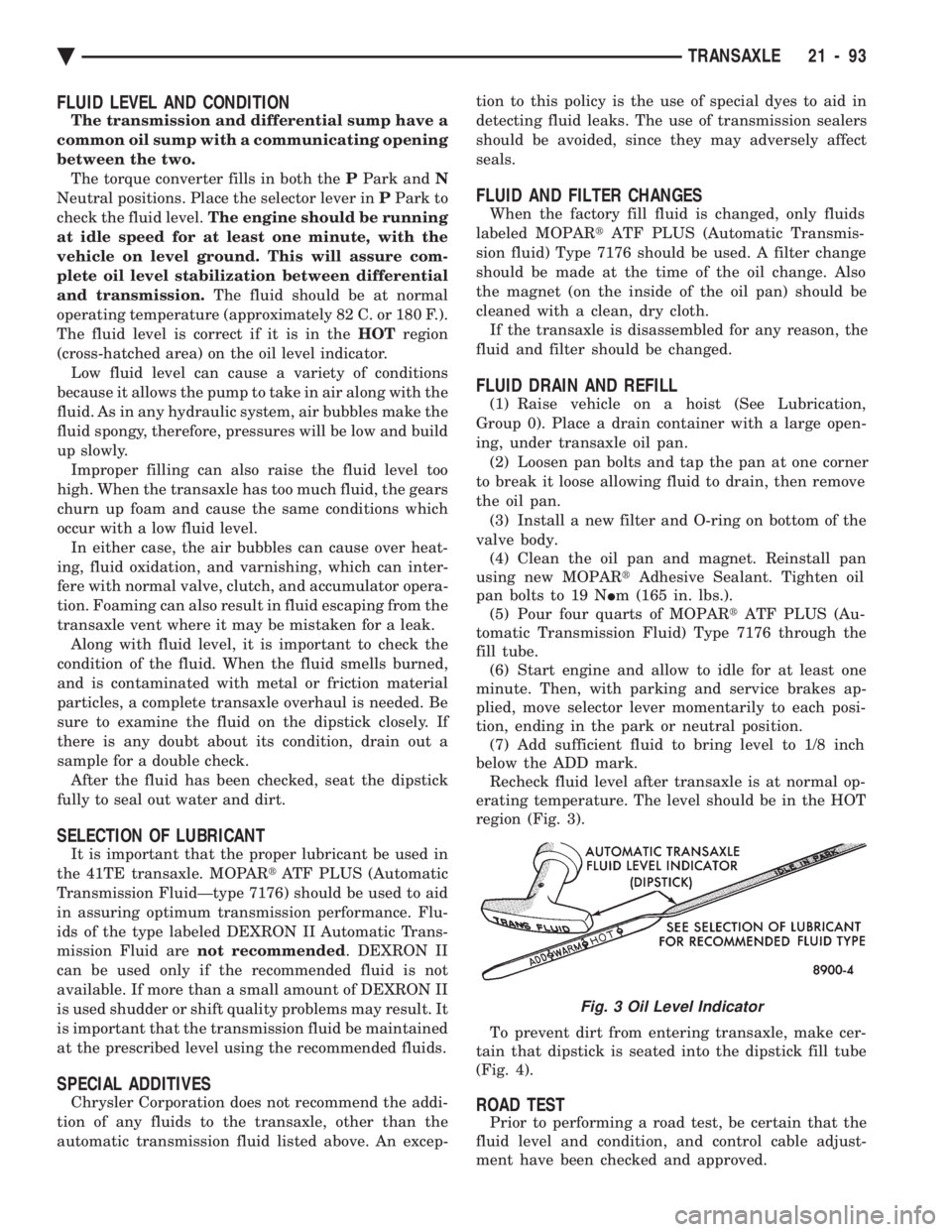
The fluid level is correct if it is in the HOTregion
(cross-hatched area) on the oil level indicator. Low fluid level can cause a variety of conditions
because it allows the pump to take in air along with the
fluid. As in any hydraulic system, air bubbles make the
fluid spongy, therefore, pressures will be low and build
up slowly. Improper filling can also raise the fluid level too
high. When the transaxle has too much fluid, the gears
churn up foam and cause the same conditions which
occur with a low fluid level. In either case, the air bubbles can cause over heat-
ing, fluid oxidation, and varnishing, which can inter-
fere with normal valve, clutch, and accumulator opera-
tion. Foaming can also result in fluid escaping from the
transaxle vent where it may be mistaken for a leak. Along with fluid level, it is important to check the
condition of the fluid. When the fluid smells burned,
and is contaminated with metal or friction material
particles, a complete transaxle overhaul is needed. Be
sure to examine the fluid on the dipstick closely. If
there is any doubt about its condition, drain out a
sample for a double check. After the fluid has been checked, seat the dipstick
fully to seal out water and dirt.
SELECTION OF LUBRICANT
It is important that the proper lubricant be used in
the 41TE transaxle. MOPAR tATF PLUS (Automatic
Transmission FluidÐtype 7176) should be used to aid
in assuring optimum transmission performance. Flu-
ids of the type labeled DEXRON II Automatic Trans-
mission Fluid are not recommended . DEXRON II
can be used only if the recommended fluid is not
available. If more than a small amount of DEXRON II
is used shudder or shift quality problems may result. It
is important that the transmission fluid be maintained
at the prescribed level using the recommended fluids.
SPECIAL ADDITIVES
Chrysler Corporation does not recommend the addi-
tion of any fluids to the transaxle, other than the
automatic transmission fluid listed above. An excep- tion to this policy is the use of special dyes to aid in
detecting fluid leaks. The use of transmission sealers
should be avoided, since they may adversely affect
seals.
FLUID AND FILTER CHANGES
When the factory fill fluid is changed, only fluids
labeled MOPAR tATF PLUS (Automatic Transmis-
sion fluid) Type 7176 should be used. A filter change
should be made at the time of the oil change. Also
the magnet (on the inside of the oil pan) should be
cleaned with a clean, dry cloth. If the transaxle is disassembled for any reason, the
fluid and filter should be changed.
FLUID DRAIN AND REFILL
(1) Raise vehicle on a hoist (See Lubrication,
Group 0). Place a drain container with a large open-
ing, under transaxle oil pan. (2) Loosen pan bolts and tap the pan at one corner
to break it loose allowing fluid to drain, then remove
the oil pan. (3) Install a new filter and O-ring on bottom of the
valve body. (4) Clean the oil pan and magnet. Reinstall pan
using new MOPAR tAdhesive Sealant. Tighten oil
pan bolts to 19 N Im (165 in. lbs.).
(5) Pour four quarts of MOPAR tATF PLUS (Au-
tomatic Transmission Fluid) Type 7176 through the
fill tube. (6) Start engine and allow to idle for at least one
minute. Then, with parking and service brakes ap-
plied, move selector lever momentarily to each posi-
tion, ending in the park or neutral position. (7) Add sufficient fluid to bring level to 1/8 inch
below the ADD mark. Recheck fluid level after transaxle is at normal op-
erating temperature. The level should be in the HOT
region (Fig. 3).
To prevent dirt from entering transaxle, make cer-
tain that dipstick is seated into the dipstick fill tube
(Fig. 4).
ROAD TEST
Prior to performing a road test, be certain that the
fluid level and condition, and control cable adjust-
ment have been checked and approved.
Fig. 3 Oil Level Indicator
Ä TRANSAXLE 21 - 93
Page 2058 of 2438
CAUTION: Prevent manual shaft rotation during in-
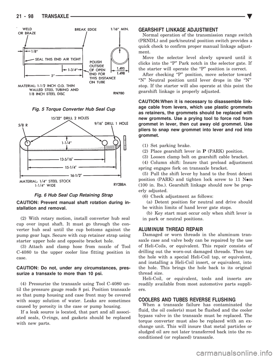
stallation and removal. (2) With rotary motion, install converter hub seal
cup over input shaft. It must go through the con-
verter hub seal until the cup bottoms against the
pump gear lugs. Secure with cup retainer strap using
starter upper hole and opposite bracket hole. (3) Attach and clamp hose from nozzle of Tool
C-4080 to the upper cooler line fitting position in
case.
CAUTION: Do not, under any circumstances, pres-
surize a transaxle to more than 10 psi.
(4) Pressurize the transaxle using Tool C-4080 un-
til the pressure gauge reads 8 psi. Position transaxle
so that pump housing and case front may be covered
with soapy solution of water. Leaks are sometimes
caused by porosity in the case or pump housing. If a leak source is located, that part and all associ-
ated seals, O-rings, and gaskets should be replaced
with new parts.
GEARSHIFT LINKAGE ADJUSTMENT
Normal operation of the transmission range switch
(PRNDL) and park/neutral position switch provides a
quick check to confirm proper manual linkage adjust-
ment. Move the selector level slowly upward until it
clicks into the ``P'' Park notch in the selector gate. If
the starter will operate the ``P'' position is correct. After checking ``P'' position, move selector toward
``N'' Neutral position until lever drops in the ``N''
stop. If the starter will also operate at this point the
gearshift linkage is properly adjusted.
CAUTION:When it is necessary to disassemble link-
age cable from levers, which use plastic grommets
as retainers, the grommets should be replaced with
new grommets. Use a prying tool to force rod from
grommet in lever, then cut away old grommet. Use
pliers to snap new grommet into lever and rod into
grommet.
(1) Set parking brake.
(2) Place gearshift lever in P(PARK) position.
(3) Loosen clamp bolt on gearshift cable bracket.
(4) Column shift: Insure that preload adjustment
spring engages fork on transaxle bracket. (5) Pull the shift lever by hand to the front detent
position (PARK) and tighten lock screw to 11 N Im
(100 in. lbs.). Gearshift linkage should now be prop-
erly adjusted. (6) Check adjustment as follows:(a) Detent position for neutral and drive should
be within limits of hand lever gate stops. (b) Key start must occur only when shift lever is
in park or neutral positions.
ALUMINUM THREAD REPAIR
Damaged or worn threads in the aluminum tran-
saxle case and valve body can be repaired by the use
of Heli-Coils, or equivalent. This repair consists of
drilling out the worn-out damaged threads. Then tap
the hole with a special Heli-Coil tap, or equivalent,
and installing a Heli-Coil insert, or equivalent, into
the hole. This brings the hole back to its original
thread size. Heli-Coil, or equivalent, tools and inserts are
readily available from most automotive parts suppli-
ers.
COOLERS AND TUBES REVERSE FLUSHING
When a transaxle failure has contaminated the
fluid, the oil cooler(s) must be flushed and the cooler
bypass valve in the transaxle must be replaced. The
torque converter must also be replaced with an ex-
change unit. This will insure that metal particles or
sludged oil are not later transferred back into the re-
conditioned (or replaced) transaxle.
Fig. 5 Torque Converter Hub Seal Cup
Fig. 6 Hub Seal Cup Retaining Strap
21 - 98 TRANSAXLE Ä
Page 2220 of 2438
INSTALLATION
Reverse the preceding operation.
FRONT CENTER CONSOLE
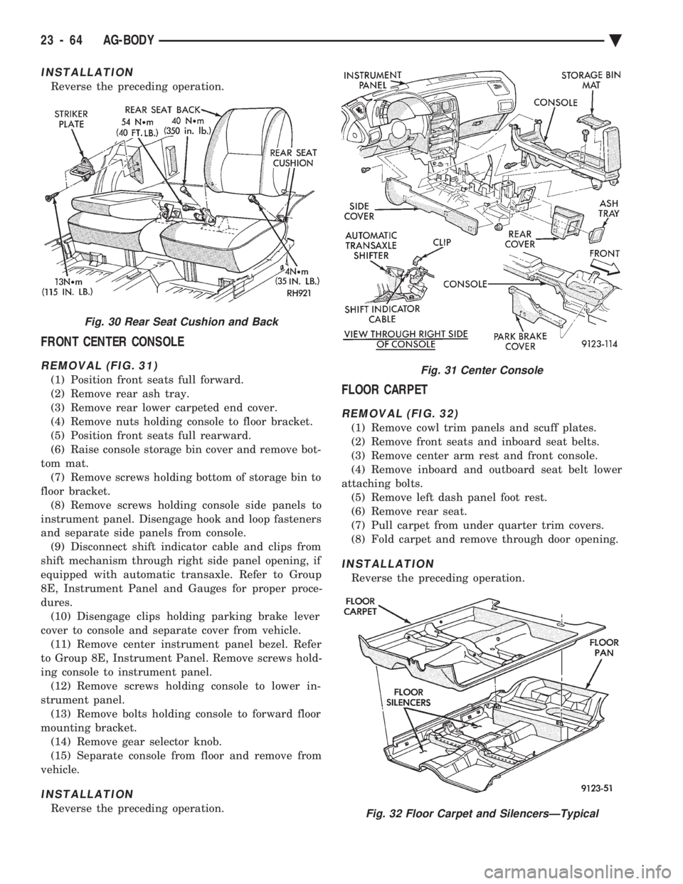
REMOVAL (FIG. 31)
(1) Position front seats full forward.
(2) Remove rear ash tray.
(3) Remove rear lower carpeted end cover.
(4) Remove nuts holding console to floor bracket.
(5) Position front seats full rearward.
(6) Raise console storage bin cover and remove bot-
tom mat. (7) Remove screws holding bottom of storage bin to
floor bracket. (8) Remove screws holding console side panels to
instrument panel. Disengage hook and loop fasteners
and separate side panels from console. (9) Disconnect shift indicator cable and clips from
shift mechanism through right side panel opening, if
equipped with automatic transaxle. Refer to Group
8E, Instrument Panel and Gauges for proper proce-
dures. (10) Disengage clips holding parking brake lever
cover to console and separate cover from vehicle. (11) Remove center instrument panel bezel. Refer
to Group 8E, Instrument Panel. Remove screws hold-
ing console to instrument panel. (12) Remove screws holding console to lower in-
strument panel. (13) Remove bolts holding console to forward floor
mounting bracket. (14) Remove gear selector knob.
(15) Separate console from floor and remove from
vehicle.
INSTALLATION
Reverse the preceding operation.
FLOOR CARPET
REMOVAL (FIG. 32)
(1) Remove cowl trim panels and scuff plates.
(2) Remove front seats and inboard seat belts.
(3) Remove center arm rest and front console.
(4) Remove inboard and outboard seat belt lower
attaching bolts. (5) Remove left dash panel foot rest.
(6) Remove rear seat.
(7) Pull carpet from under quarter trim covers.
(8) Fold carpet and remove through door opening.
INSTALLATION
Reverse the preceding operation.
Fig. 30 Rear Seat Cushion and Back
Fig. 31 Center Console
Fig. 32 Floor Carpet and SilencersÐTypical
23 - 64 AG-BODY Ä
Page 2236 of 2438
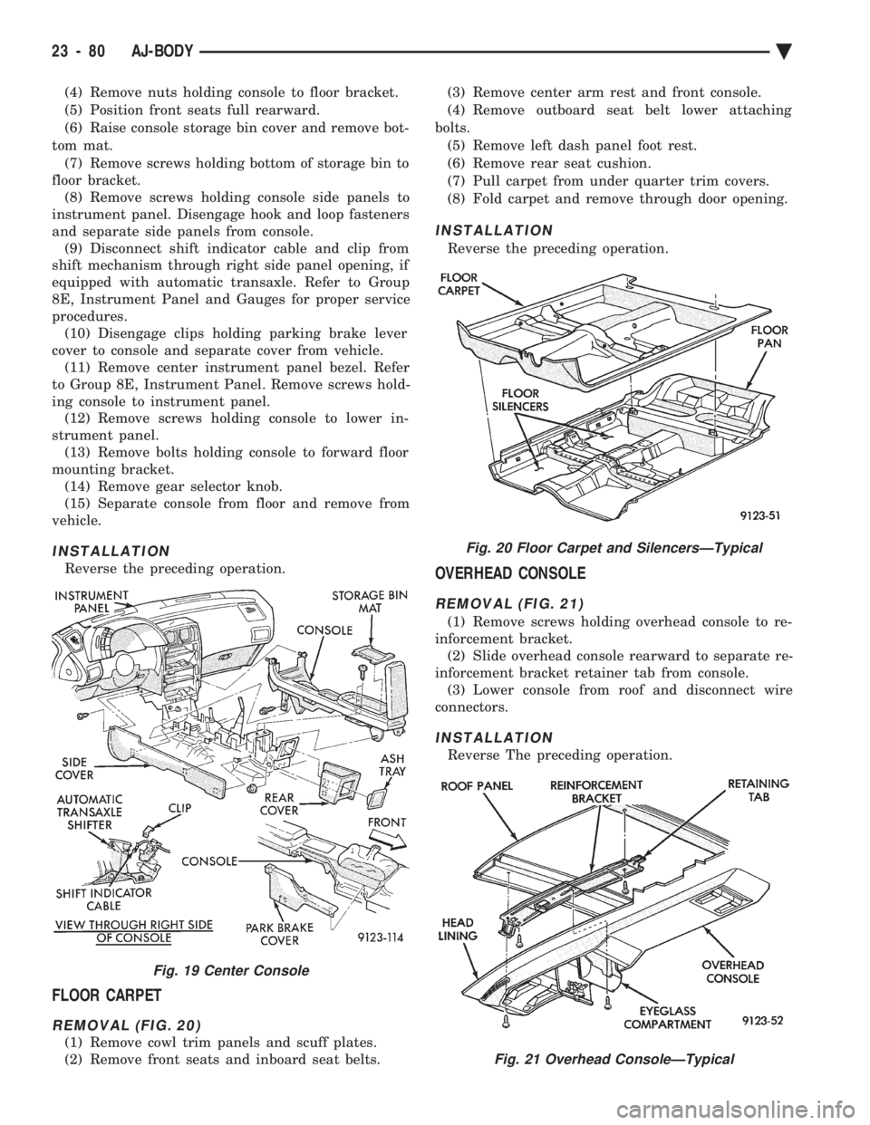
(4) Remove nuts holding console to floor bracket.
(5) Position front seats full rearward.
(6) Raise console storage bin cover and remove bot-
tom mat. (7) Remove screws holding bottom of storage bin to
floor bracket. (8) Remove screws holding console side panels to
instrument panel. Disengage hook and loop fasteners
and separate side panels from console. (9) Disconnect shift indicator cable and clip from
shift mechanism through right side panel opening, if
equipped with automatic transaxle. Refer to Group
8E, Instrument Panel and Gauges for proper service
procedures. (10) Disengage clips holding parking brake lever
cover to console and separate cover from vehicle. (11) Remove center instrument panel bezel. Refer
to Group 8E, Instrument Panel. Remove screws hold-
ing console to instrument panel. (12) Remove screws holding console to lower in-
strument panel. (13) Remove bolts holding console to forward floor
mounting bracket. (14) Remove gear selector knob.
(15) Separate console from floor and remove from
vehicle.
INSTALLATION
Reverse the preceding operation.
FLOOR CARPET
REMOVAL (FIG. 20)
(1) Remove cowl trim panels and scuff plates.
(2) Remove front seats and inboard seat belts. (3) Remove center arm rest and front console.
(4) Remove outboard seat belt lower attaching
bolts. (5) Remove left dash panel foot rest.
(6) Remove rear seat cushion.
(7) Pull carpet from under quarter trim covers.
(8) Fold carpet and remove through door opening.
INSTALLATION
Reverse the preceding operation.
OVERHEAD CONSOLE
REMOVAL (FIG. 21)
(1) Remove screws holding overhead console to re-
inforcement bracket. (2) Slide overhead console rearward to separate re-
inforcement bracket retainer tab from console. (3) Lower console from roof and disconnect wire
connectors.
INSTALLATION
Reverse The preceding operation.
Fig. 19 Center Console
Fig. 20 Floor Carpet and SilencersÐTypical
Fig. 21 Overhead ConsoleÐTypical
23 - 80 AJ-BODY Ä
Page 2366 of 2438
AA BODY PROCEDURE
WARNING: IF EQUIPPED WITH A/C, THE REFRIG-
ERATION SYSTEM MUST BE COMPLETELY EMPTY
BEFORE PROCEEDING WITH THIS OPERATION. Refer to Group 8E and Group 23 for component re-
moval and installation when performing this opera-
tion. (1) Perform steps 1 through 7 of Blower Motor re-
moval and installation. (2) Remove relay panel above glove compartment
opening. (3) Disconnect the A/C vacuum line connector and
radio noise capacitor connectors. (4) Remove left windshield pillar trim cover.
(5) Remove left lower side cowl trim cover.
(6) Remove hood release handle mechanism attach-
ing screws. (7) Remove steering column trim covers.
(8) Disconnect parking brake release mechanism
connecting rod. Gain access through fuse panel open-
ing. (9) Remove lower left instrument panel silencer.
(10) Remove lower left instrument panel reinforce-
ment. (11) Remove instrument panel center (radio) bezel.
(12) Remove forward floor console.
(13) Remove the radio.
(14) Remove the heater-A/C control.
(15) Remove cigar lighter.
(16) Remove message center/trip computer, if
equipped. (17) Disconnect side window demister tubes from
top of heat A/C unit. (18) Remove steering column upper attaching bolts
and allow the steering wheel to rest on the driver
seat cushion. (19) Remove upper instrument panel (defroster
outlet) cover. (20) Remove upper instrument panel attaching
screws from below the windshield opening. (21) Loosen (do not remove) the left lower cowl in-
strument panel attaching screw. (22) Remove the right lower cowl instrument panel
attaching screw.
CAUTION: Protect the passenger seat cover from
soiling or damage using a suitable cover.
(23) Carefully pull the right side of the instrument
panel away from the vehicle. Allow the instrument
panel to rest on the passenger seat cushion.
CAUTION: Before proceeding with the next opera-
tion, review the Safety Precautions and Warnings at
the front of this Group. (24) From the engine compartment, drain the cool-
ing system and disconnect the heater hoses from the
heater core nipples. Plug the nipples to avoid spilling
coolant inside the vehicle. (25) Disconnect the refrigerant lines from the ex-
pansion-valve at the dash panel on the right side of
the vehicle. Seal the refrigerant lines to prevent con-
tamination. (26) Remove the expansion valve from the evapo-
rator plate. Seal the valve to avoid contamination. (27) Remove the condensate drain tube.
(28) Remove heater-A/C unit to dash panel attach-
ing nuts. (29) From inside the vehicle, pull rearward on the
heater-A/C unit to clear the dash panel silencer and
remove the unit from the vehicle. To install, reverse the preceding operation. Refill
cooling system and test for leaks. Evacuate and
charge the refrigerant system and test overall perfor-
mance.
AG, AJ BODY PROCEDURE
WARNING: IF EQUIPPED WITH A/C, THE REFRIG-
ERATION SYSTEM MUST BE COMPLETELY EMPTY
BEFORE PROCEEDING WITH THIS OPERATION.
(1) Disconnect the battery negative cable.
(2) Drain the coolant from cooling system. Refer to
Group 7, Cooling System. (3) Remove the air conditioner expansion valve (if
equipped). (4) Disconnect the heater hoses from heater core.
Then plug or cap the tubes on heater core. This will
prevent spilling coolant into the interior of vehicle
during unit removal. (5) Remove the condensate drain tube.
(6) Disconnect the A/C-heater vacuum supply line
from vacuum supply nipple (in the engine compart-
ment). (7) Remove the four A/C-heater assembly-to-dash
panel attaching nuts. (8) Remove the passenger side front seat. Refer to
Group 23, Body. (9) Remove the kick panel/sill cover at right door
opening. (10) Remove the body computer (Fig. 6) located at
the lower right section of the right front door pillar. (11) Remove the glove box assembly. Refer to
Group 8E, Instrument Panel. (12) Remove the carpeted panels from both sides of
the console. (13) Un-clip the radio antenna cable from the
metal support (Fig. 6) located behind and below the
glove box opening. (14) Instrument panel removal is not necessary to
remove the A/C-heater assembly from the vehicle.
24 - 62 HEATING AND AIR CONDITIONING Ä
Page 2403 of 2438
POSITIVE CRANKCASE VENTILATION (PCV)
SYSTEMS
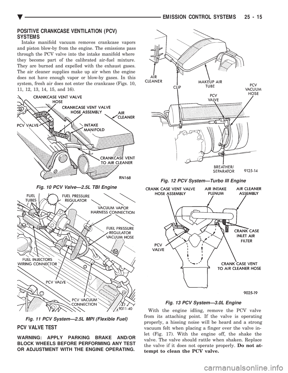
Intake manifold vacuum removes crankcase vapors
and piston blow-by from the engine. The emissions pass
through the PCV valve into the intake manifold where
they become part of the calibrated air-fuel mixture.
They are burned and expelled with the exhaust gases.
The air cleaner supplies make up air when the engine
does not have enough vapor or blow-by gases. In this
system, fresh air does not enter the crankcase (Figs. 10,
11, 12, 13, 14, 15, and 16).
PCV VALVE TEST
WARNING: APPLY PARKING BRAKE AND/OR
BLOCK WHEELS BEFORE PERFORMING ANY TEST
OR ADJUSTMENT WITH THE ENGINE OPERATING. With the engine idling, remove the PCV valve
from its attaching point. If the valve is operating
properly, a hissing noise will be heard and a strong
vacuum felt when placing a finger over the valve in-
let (Fig. 17). With the engine off, the shake the
valve. The valve should rattle when shaken. Replace
the valve if it does not operate properly. Do not at-
tempt to clean the PCV valve.
Fig. 10 PCV ValveÐ2.5L TBI Engine
Fig. 11 PCV SystemÐ2.5L MPI (Flexible Fuel)
Fig. 12 PCV SystemÐTurbo III Engine
Fig. 13 PCV SystemÐ3.0L Engine
Ä EMISSION CONTROL SYSTEMS 25 - 15
Page 2409 of 2438
These systems do not allow EGR at idle. The 2.2L/
2.5L EGR systems operate at all temperatures. The
3.0L, 3.3L and 3.8L EGR systems do not operate
when coolant temperature is below 4.5ÉC (40É)F at
start-up. These systems activate when coolant tem-
perature reaches 77ÉC (170ÉF).
EGR SYSTEM ON-BOARD DIAGNOSTICS
The powertrain control module (PCM) performs an
on-board diagnostic check of the EGR system on all
California vehicles with EGR systems. The diagnos-
tic system uses the Electric EGR Transducer (EET)
for the system tests. The diagnostic check activates only during selected
engine/driving conditions. When the conditions are
met, the PCM energizes the transducer solenoid to
disable the EGR. The PCM checks for a change in the oxygen sensor signal. If the air-fuel mixture goes
lean, the PCM will attempt to enrichen the mixture.
The PCM registers a fault if the EGR system has
failed or degraded. After registering a fault, the PCM
turns on the malfunction indicator lamp (instrument
panel Check Engine light). The malfunction indicator
lamp indicates the need for immediate service.
If a problem is indicated by the malfunction indicator
lamp and a diagnostic trouble code for the EGR system,
check for proper operation of the EGR system. Use the
System Test, EGR Gas Flow Test and EGR Diagnosis
Chart. If the EGR system tests properly, check the sys-
tem using the DRBII scan tool. Refer to On-Board Di-
agnosis in the General Diagnosis sections of Group 14.
Also, refer to the DRBII scan tool and the appropriate
Powertrain Diagnostics Procedure manual.
EXHAUST GAS RECIRCULATION (EGR) SYSTEM
TEST
WARNING: APPLY PARKING BRAKE AND/OR
BLOCK WHEELS BEFORE PERFORMING EGR SYS-
TEM TEST.
A failed or malfunctioning EGR system can cause
engine spark knock, sags or hesitation, rough idle,
and/or engine stalling. To ensure proper operation of
the EGR system, all passages and moving parts must
be free of deposits that could cause plugging or stick-
ing. Ensure system hoses do not leak. Replace leak-
ing components. Inspect hose connections between the throttle body,
intake manifold, EGR solenoid and transducer, and
EGR valve. Replace hardened, cracked, or melted
hoses. Repair or replace faulty connectors.
Check the EGR control system and EGR valve with
the engine fully warmed up and running (engine cool-
ant temperature over 150ÉF). With the transmission in
neutral and the throttle closed, allow the engine to idle
for 70 seconds. Abruptly accelerate the engine to ap-
proximately 2000 rpm, but not over 3000 rpm. The EGR
valve stem should move when accelerating the engine
(the relative position of the groove on the EGR valve
stem should change). Repeat the test several times to
confirm movement. If the EGR valve stem moves, the
control system is operating normally. If the control sys-
tem is not operating normally, refer to the EGR Diag-
nosis Chart to determine the cause.
EGR GAS FLOW TEST
The following procedure should be used to determine
if exhaust gas is flowing through the EGR system.
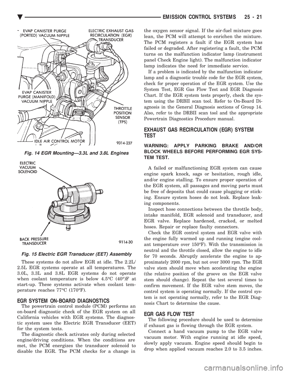
Connect a hand vacuum pump to the EGR valve
vacuum motor. With engine running at idle speed,
slowly apply vacuum. Engine speed should begin to
drop when applied vacuum reaches 2.0 to 3.5 inches.
Fig. 14 EGR MountingÐ3.3L and 3.8L Engines
Fig. 15 Electric EGR Transducer (EET) Assembly
Ä EMISSION CONTROL SYSTEMS 25 - 21