1993 CHEVROLET PLYMOUTH ACCLAIM parking brake
[x] Cancel search: parking brakePage 237 of 2438

ABS BRAKING SYSTEM DIAGNOSIS
WARNING: SOME OPERATIONS IN THIS SECTION
REQUIRE THAT HYDRAULIC TUBES, HOSES AND
FITTINGS BE DISCONNECTED FOR INSPECTION
OR TESTING PURPOSES. THIS BRAKE SYSTEM
USES A HYDRAULIC ACCUMULATOR THAT, WHEN
FULLY CHARGED, CONTAINS BRAKE FLUID AT
HIGH PRESSURE. BEFORE DISCONNECTING ANY
HYDRAULIC TUBE, HOSE OR FITTING. BE SURE
THAT THE ACCUMULATOR IS FULLY DE-PRES-
SURIZED AS DESCRIBED IN THIS SECTION. FAIL-
URE TO DE-PRESSURIZE THE ACCUMULATOR
MAY RESULT IN PERSONAL INJURY AND/OR DAM-
AGE TO PAINTED SURFACES.
CAUTION: Certain components of the Anti-Lock
Brake System (ABS) are not intended to be serviced
individually. Attempting to remove or disconnect
certain system components, may result in personal
injury and/or improper system operation. Only
those components with approved removal, service
and installation procedures described in this man-
ual should be serviced.
GENERAL INFORMATION
This section contains information necessary to di-
agnosis mechanical conditions that can affect opera-
tion of the Bendix Anti-Lock 10 Brake System.
Specifically, this section should be used to help diag-
nose mechanical conditions that result in any of the
following:
CAUTION: Review this entire section before per-
forming any mechanical work on a vehicle equipped
with the Bendix Anti-Lock 10 brake system. For in-
formation on precautions pertaining to potential
component damage, vehicle damage and personal
injury.
(1) Anti-Lock warning lamp illuminated
(2) BRAKE warning lamp on
(3) Lack of Power Assist or Excessive Pedal Travel
(4) Brakes Lock on Hard Application
Diagnosis of conditions that are obviously mechan-
ical in nature. Such as brake noise, brake pulsation,
or vehicle vibration during normal braking. Should
be directed to Group 5 Brakes in the service manual.
This also pertains to problems involving the parking
brake system.
Fig. 13 Hold Pressure - Hydraulic Control
Ä ANTI-LOCK 10 BRAKE SYSTEM 5 - 87
Page 273 of 2438

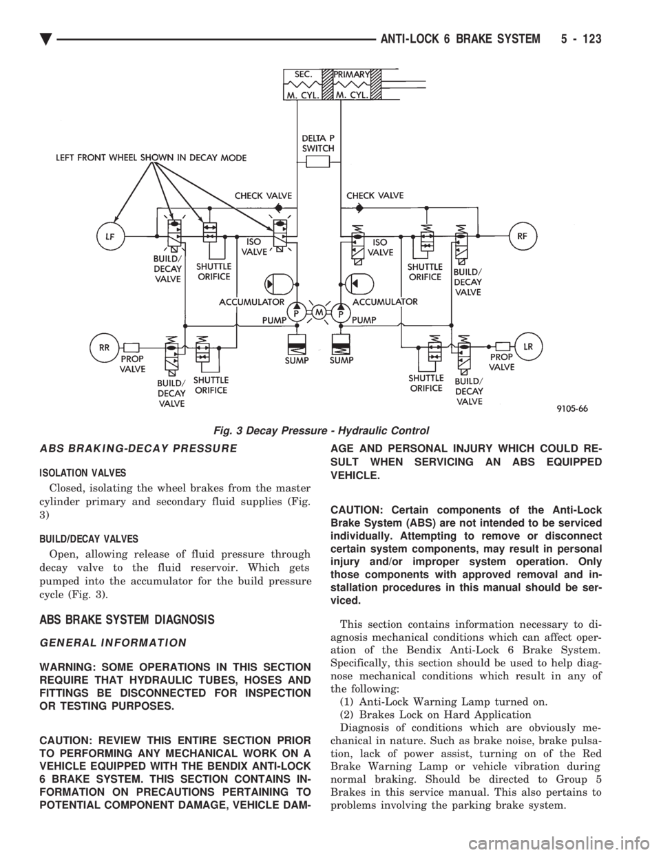
ABS BRAKING-DECAY PRESSURE
ISOLATION VALVES Closed, isolating the wheel brakes from the master
cylinder primary and secondary fluid supplies (Fig.
3)
BUILD/DECAY VALVES
Open, allowing release of fluid pressure through
decay valve to the fluid reservoir. Which gets
pumped into the accumulator for the build pressure
cycle (Fig. 3).
ABS BRAKE SYSTEM DIAGNOSIS
GENERAL INFORMATION
WARNING: SOME OPERATIONS IN THIS SECTION
REQUIRE THAT HYDRAULIC TUBES, HOSES AND
FITTINGS BE DISCONNECTED FOR INSPECTION
OR TESTING PURPOSES.
CAUTION: REVIEW THIS ENTIRE SECTION PRIOR
TO PERFORMING ANY MECHANICAL WORK ON A
VEHICLE EQUIPPED WITH THE BENDIX ANTI-LOCK
6 BRAKE SYSTEM. THIS SECTION CONTAINS IN-
FORMATION ON PRECAUTIONS PERTAINING TO
POTENTIAL COMPONENT DAMAGE, VEHICLE DAM- AGE AND PERSONAL INJURY WHICH COULD RE-
SULT WHEN SERVICING AN ABS EQUIPPED
VEHICLE.
CAUTION: Certain components of the Anti-Lock
Brake System (ABS) are not intended to be serviced
individually. Attempting to remove or disconnect
certain system components, may result in personal
injury and/or improper system operation. Only
those components with approved removal and in-
stallation procedures in this manual should be ser-
viced.
This section contains information necessary to di-
agnosis mechanical conditions which can affect oper-
ation of the Bendix Anti-Lock 6 Brake System.
Specifically, this section should be used to help diag-
nose mechanical conditions which result in any of
the following: (1) Anti-Lock Warning Lamp turned on.
(2) Brakes Lock on Hard Application
Diagnosis of conditions which are obviously me-
chanical in nature. Such as brake noise, brake pulsa-
tion, lack of power assist, turning on of the Red
Brake Warning Lamp or vehicle vibration during
normal braking. Should be directed to Group 5
Brakes in this service manual. This also pertains to
problems involving the parking brake system.
Fig. 3 Decay Pressure - Hydraulic Control
Ä ANTI-LOCK 6 BRAKE SYSTEM 5 - 123
Page 297 of 2438

The instrument panel bulb can be checked each
time the ignition switch is turned to the start posi-
tion or the parking brake is set.
HYDRAULIC SYSTEM SERVICE PROCEDURES
BRAKE WARNING SYSTEM
CHECKING BRAKE WARNING SWITCH UNIT
The Red Brake Warning light will come on when the
parking brake is applied with the ignition key turned
ON. The same light will also illuminate should one of
the two service brake hydraulic systems fail.
CAUTION:Make sure air does not enter the hydraulic
system during this test procedure. See bleeding with-
out a pressure bleeder at the beginning of this section
for master cylinder fluid level checking procedures.
To test the service brake warning system lamp.
Raise vehicle on a hoist and open a wheel cylinder
bleeder while a helper depresses the brake pedal and
observes the warning light.
If light fails to come on, inspect for a burned out bulb,
disconnected socket, or a broken or disconnected wire at
the switch. If the bulb is not burned out and the wire
continuity is not interrupted. Check the service brake
warning switch operation with a test lamp between the
switch terminal and a known good ground. Be sure to
fill master cylinder and bleed brake system after correc-
tion has been made, if necessary.
TESTING ANTILOCK PROPORTIONING VALVES
(1) Install one gauge and (TEE) between modula-
tor assembly and male end (Inlet) of proportioning
valve (Fig. 4). (2) Install second gauge at female end (Outlet) of
proportioning valve (Fig. 4).
(3) Have a helper exert pressure on brake pedal to
obtain and hold required pressure reading on the
valve inlet gauge. (4) Check reading on outlet gauge. If inlet and out-
let pressures do not agree with the following chart,
replace the valve. See (Fig. 3) for proportioning valve
identification.
BENDIX ANTILOCK 4 PROPORTIONING VALVE APPLICATIONS
BENDIX ANTILOCK 4 PROPORTIONING VALVE PRESSURES
Fig. 4 Tube Connections for ABS
Ä BRAKES 5 - 11
Page 385 of 2438

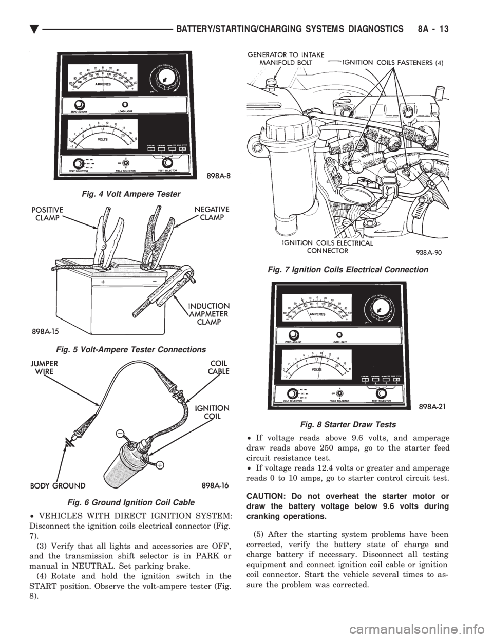
² VEHICLES WITH DIRECT IGNITION SYSTEM:
Disconnect the ignition coils electrical connector (Fig.
7). (3) Verify that all lights and accessories are OFF,
and the transmission shift selector is in PARK or
manual in NEUTRAL. Set parking brake. (4) Rotate and hold the ignition switch in the
START position. Observe the volt-ampere tester (Fig.
8). ²
If voltage reads above 9.6 volts, and amperage
draw reads above 250 amps, go to the starter feed
circuit resistance test.
² If voltage reads 12.4 volts or greater and amperage
reads 0 to 10 amps, go to starter control circuit test.
CAUTION: Do not overheat the starter motor or
draw the battery voltage below 9.6 volts during
cranking operations.
(5) After the starting system problems have been
corrected, verify the battery state of charge and
charge battery if necessary. Disconnect all testing
equipment and connect ignition coil cable or ignition
coil connector. Start the vehicle several times to as-
sure the problem was corrected.
Fig. 4 Volt Ampere Tester
Fig. 5 Volt-Ampere Tester Connections
Fig. 6 Ground Ignition Coil Cable
Fig. 7 Ignition Coils Electrical Connection
Fig. 8 Starter Draw Tests
Ä BATTERY/STARTING/CHARGING SYSTEMS DIAGNOSTICS 8A - 13
Page 387 of 2438

STARTER CONTROL CIRCUIT TESTS
The starter control circuit has:
² Starter solenoid
² Starter relay (Fig. 2)
² Neutral starting and back-up switch with auto-
matic transmissions
² Clutch pedal mounted starter interlock switch
with manual transmissions
² Ignition switch
² Battery
² All related wiring and connections
CAUTION: Before performing any starter tests, the
ignition system must be disabled.
² VEHICLES EQUIPPED WITH A CONVEN-
TIONAL DISTRIBUTOR: Disconnect coil wire from
distributor cap center tower. Secure wire to a good
ground to prevent engine from starting (Fig. 6).
² VEHICLES EQUIPPED WITH DIRECT IGNI-
TION SYSTEM: Unplug the coils electrical connector
(Fig. 7).
STARTER SOLENOID TEST
WARNING: CHECK TO ENSURE THAT THE TRANS-
MISSION IS IN PARK OR NEUTRAL WITH THE
PARKING BRAKE APPLIED
(1) Verify battery condition. Battery must be in
good condition with a full charge before performing
any starter tests. Refer to Battery Tests. (2) Perform this starter solenoid test BEFORE per-
forming the starter relay test. (3) Raise the vehicle.
(4) Perform a visual inspection of the starter/
starter solenoid for corrosion, loose connections or
faulty wiring. (5) Lower the vehicle.
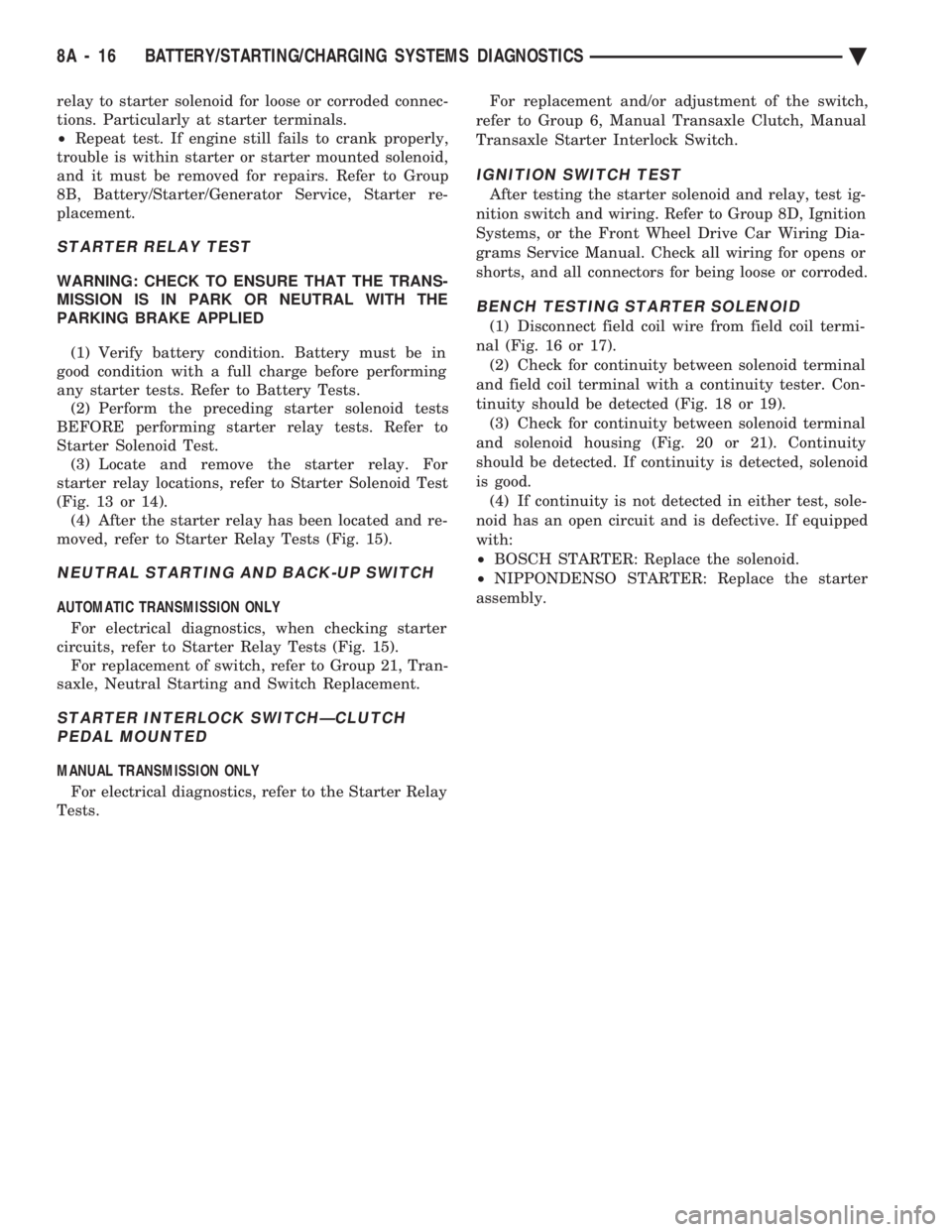
(6) Locate the starter relay as follows:
² On AC, AG, AJ and AY Bodies the relay is located
in the Power Distribution Center. This Center is mounted near the front of the left front strut tower
(Fig. 13). The position of the starter relay within this
Center will be shown on the Center cover.
² On AA/AP Bodies the relay is located on the front
of the left front strut tower (Fig. 14).
(7) Remove the starter relay from the connector.
(8) Connect a remote starter switch or a jumper
wire between the battery positive post and terminal
87 on the starter relay connector. To decide the
starter relay terminal numbers, refer to the Starter
Relay Tests.
² If engine now cranks, starter/starter solenoid is
good. Go to the starter relay test.
² If engine does not crank with this test, or solenoid
chatters, check wiring and connectors from starter
Fig. 12 Test Positive Battery Cable Resistance
Fig. 13 Starter Relay LocationÐAC, AG, AJ, and AY Bodies
Fig. 14 Starter Relay LocationÐAA/AP Body
Ä BATTERY/STARTING/CHARGING SYSTEMS DIAGNOSTICS 8A - 15
Page 388 of 2438

relay to starter solenoid for loose or corroded connec-
tions. Particularly at starter terminals.
² Repeat test. If engine still fails to crank properly,
trouble is within starter or starter mounted solenoid,
and it must be removed for repairs. Refer to Group
8B, Battery/Starter/Generator Service, Starter re-
placement.
STARTER RELAY TEST
WARNING: CHECK TO ENSURE THAT THE TRANS-
MISSION IS IN PARK OR NEUTRAL WITH THE
PARKING BRAKE APPLIED
(1) Verify battery condition. Battery must be in
good condition with a full charge before performing
any starter tests. Refer to Battery Tests. (2) Perform the preceding starter solenoid tests
BEFORE performing starter relay tests. Refer to
Starter Solenoid Test. (3) Locate and remove the starter relay. For
starter relay locations, refer to Starter Solenoid Test
(Fig. 13 or 14). (4) After the starter relay has been located and re-
moved, refer to Starter Relay Tests (Fig. 15).
NEUTRAL STARTING AND BACK-UP SWITCH
AUTOMATIC TRANSMISSION ONLY
For electrical diagnostics, when checking starter
circuits, refer to Starter Relay Tests (Fig. 15). For replacement of switch, refer to Group 21, Tran-
saxle, Neutral Starting and Switch Replacement.
STARTER INTERLOCK SWITCHÐCLUTCH PEDAL MOUNTED
MANUAL TRANSMISSION ONLY
For electrical diagnostics, refer to the Starter Relay
Tests. For replacement and/or adjustment of the switch,
refer to Group 6, Manual Transaxle Clutch, Manual
Transaxle Starter Interlock Switch.
IGNITION SWITCH TEST
After testing the starter solenoid and relay, test ig-
nition switch and wiring. Refer to Group 8D, Ignition
Systems, or the Front Wheel Drive Car Wiring Dia-
grams Service Manual. Check all wiring for opens or
shorts, and all connectors for being loose or corroded.
BENCH TESTING STARTER SOLENOID
(1) Disconnect field coil wire from field coil termi-
nal (Fig. 16 or 17). (2) Check for continuity between solenoid terminal
and field coil terminal with a continuity tester. Con-
tinuity should be detected (Fig. 18 or 19). (3) Check for continuity between solenoid terminal
and solenoid housing (Fig. 20 or 21). Continuity
should be detected. If continuity is detected, solenoid
is good. (4) If continuity is not detected in either test, sole-
noid has an open circuit and is defective. If equipped
with:
² BOSCH STARTER: Replace the solenoid.
² NIPPONDENSO STARTER: Replace the starter
assembly.
8A - 16 BATTERY/STARTING/CHARGING SYSTEMS DIAGNOSTICS Ä
Page 453 of 2438

2.2L TBI, 2.5L TBI, 2.5L MPI AND 3.0L IGNITION SYSTEMSÐDIAGNOSTIC PROCEDURES
INDEX
page page
Coolant Temperature Sensor Test ............ 13
Failure to Start TestÐ2.5L TBI and 3.0L Engines . 12
General Information ....................... 11
Ignition Coil ............................. 11 Manifold Absolute Pressure (MAP) Sensor Test . 13
Poor Performance Test .................... 13
Spark Plugs ............................ 11
Testing for Spark at Coil ................... 11
GENERAL INFORMATION
For additional information, refer to On Board Di-
agnostics in the Fuel Injection General Diagnosis
sections of Group 14. Also, refer to the DRBII scan
tool and appropriate Powertrain Diagnostic Proce-
dures Manual.
SPARK PLUGS
Faulty or fouled spark plugs may perform well at
idle speed, but frequently fail at higher engine
speeds. Faulty plugs can be identified in a number of
ways: poor fuel economy, power loss, decrease in en-
gine speed, hard starting and, in general, poor en-
gine performance. Spark plugs also malfunction because of carbon
fouling, excessive electrode air gap, or a broken insu-
lator. Refer to the General Information Section of
this group for spark plug diagnosis.
IGNITION COIL
The ignition coil is designed to operate without an
external ballast resistor. Inspect the coil for arcing. Test the coil according
to coil tester manufacturer's instructions. Test coil
primary and secondary resistance. Replace any coil
that does not meet specifications. Refer to the Coil
Resistance chart. If the ignition coil is replaced due to a burned
tower, carbon tracking, arcing at the tower, or dam-
age to the terminal or boot on the coil end of the sec-
ondary cable, the cable must be replaced. Arcing at the tower will carbonize the nipple which, if it is con-
nected to a new coil, will cause the coil to fail. If a secondary cable shows any signs of damage,
the cable should be replaced with a new cable and
new terminal. Carbon tracking on the old cable can
cause arcing and the failure of a new coil.
TESTING FOR SPARK AT COIL
WARNING: APPLY PARKING BRAKE AND/OR
BLOCK THE WHEELS BEFORE PERFORMING ANY
TEST WITH THE ENGINE RUNNING.
CAUTION: Spark plug cables may be damaged if
this test is performed with more than 1/4 inch clear-
ance between the cable and engine ground.
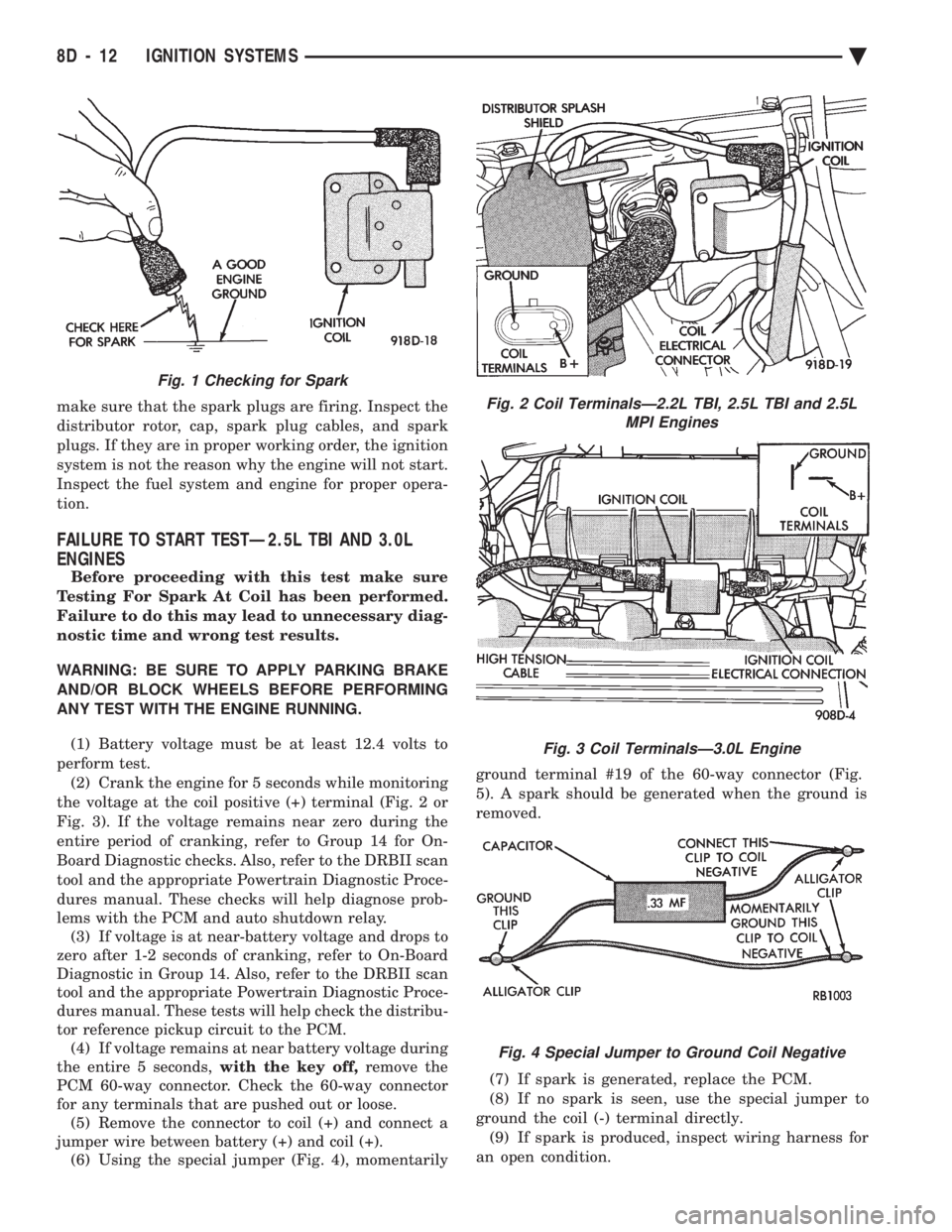
Remove the coil secondary cable from the distribu-
tor cap. Hold the end of cable about 6 mm (1/4-inch)
away from a good engine ground (Fig. 1). Crank the
engine and inspect for spark at the coil secondary ca-
ble. There must be a constant spark at the coil second-
ary cable. If the spark is constant, have a helper con-
tinue to crank engine and, while slowly moving coil
secondary cable away from ground, look for arcing at
the coil tower. If arcing occurs at the tower, replace
the coil. If spark is not constant or there is no spark,
proceed to the failure to start test. If a constant spark is present and no arcing occurs
at the coil tower, the ignition system is producing
the necessary high secondary voltage. However,
COIL RESISTANCE
Ä IGNITION SYSTEMS 8D - 11
Page 454 of 2438

make sure that the spark plugs are firing. Inspect the
distributor rotor, cap, spark plug cables, and spark
plugs. If they are in proper working order, the ignition
system is not the reason why the engine will not start.
Inspect the fuel system and engine for proper opera-
tion.
FAILURE TO START TESTÐ2.5L TBI AND 3.0L
ENGINES
Before proceeding with this test make sure
Testing For Spark At Coil has been performed.
Failure to do this may lead to unnecessary diag-
nostic time and wrong test results.
WARNING: BE SURE TO APPLY PARKING BRAKE
AND/OR BLOCK WHEELS BEFORE PERFORMING
ANY TEST WITH THE ENGINE RUNNING.
(1) Battery voltage must be at least 12.4 volts to
perform test. (2) Crank the engine for 5 seconds while monitoring
the voltage at the coil positive (+) terminal (Fig. 2 or
Fig. 3). If the voltage remains near zero during the
entire period of cranking, refer to Group 14 for On-
Board Diagnostic checks. Also, refer to the DRBII scan
tool and the appropriate Powertrain Diagnostic Proce-
dures manual. These checks will help diagnose prob-
lems with the PCM and auto shutdown relay. (3) If voltage is at near-battery voltage and drops to
zero after 1-2 seconds of cranking, refer to On-Board
Diagnostic in Group 14. Also, refer to the DRBII scan
tool and the appropriate Powertrain Diagnostic Proce-
dures manual. These tests will help check the distribu-
tor reference pickup circuit to the PCM. (4) If voltage remains at near battery voltage during
the entire 5 seconds, with the key off,remove the
PCM 60-way connector. Check the 60-way connector
for any terminals that are pushed out or loose. (5) Remove the connector to coil (+) and connect a
jumper wire between battery (+) and coil (+). (6) Using the special jumper (Fig. 4), momentarily ground terminal #19 of the 60-way connector (Fig.
5). A spark should be generated when the ground is
removed.
(7) If spark is generated, replace the PCM.
(8) If no spark is seen, use the special jumper to
ground the coil (-) terminal directly. (9) If spark is produced, inspect wiring harness for
an open condition.
Fig. 2 Coil TerminalsÐ2.2L TBI, 2.5L TBI and 2.5L MPI Engines
Fig. 3 Coil TerminalsÐ3.0L Engine
Fig. 4 Special Jumper to Ground Coil Negative
Fig. 1 Checking for Spark
8D - 12 IGNITION SYSTEMS Ä