1993 CHEVROLET PLYMOUTH ACCLAIM fuse
[x] Cancel search: fusePage 700 of 2438
(1) Be sure that the module has a battery feed
from the 20 Amp breaker in cavity 1 of the black
connector. Also affected would be the optical horn
and the stop lamps. (2) Be sure that the module has an ignition feed
from 5 Amp fuse in cavity 8 of the black connector.
Also affected would be the body computer, instru-
ment cluster and message center. (3) Be sure that the module has a ground from the
right side cowl behind the body computer to the cav-
ity 5 of the black connector. (4) Be sure that you are supplying a good ground
to the programming wire. (5) If the above circuits are good, replace the Re-
ceiver Module. CONDITION: Doors can be locked or unlocked with
the Keyless Entry transmitter. But the doors will not
lock. The Vehicle Theft Alarm system will not arm,
when using only the power door LOCK switch in the
driver's door. (1) Be sure you have not left key in the ignition
column lock cylinder. (2) If step 1 is OK, check the Key in Lock switch
circuit in the steering column for a short to ground. (3) In this problem the body computer controls the
LOCK function. Be sure that it is providing a battery
voltage output to the door lock relay. The door lock
relay controls the door lock motors. CONDITION: Doors will lock but Vehicle Theft
System will not arm when using the transmitter. (1) The Keyless Entry Receiver Module controls
the door lock signal to the door lock relay. The door
lock relay controls the door lock motors. Check for
battery voltage at cavity 10 of the Theft Alarm mod-
ule from the Receiver module. (2) If voltage is OK, replace Receiver module.
CONDITION: All doors except driver's door will
lock with the transmitter. (1) Test the driver's door output of the Receiver
Module for a ground. (2) If there is no ground at the pin, replace the Re-
ceiver module. (3) If there is a ground at the output, replace the
door lock motor. CONDITION: Only driver's door will lock with the
transmitter.
² Repair ground circuit to unlock relay
² Replace unlock relay
CONDITION: Doors do not lock with the transmit-
ter, but still get horn CHIRP that indicates that they
did lock. Replace Receiver module. CONDITION: Doors will lock with the transmitter
but there is no horn CHIRP. (1) Press horn button, listen horn sound.
(2) If the horn sounded, change horn relay. (3) Still no CHIRP, check continuity between the
horn relay and the receiver output pin. Repair as
necessary. (4) Still no horn CHIRP, replace the receiver mod-
ule. (5) If using a DRB II, refer to Body Diagnostic Pro-
cedures.
REMOTE KEYLESS MODULE REPLACEMENT
(1) Remove lower right instrument panel silencer.
(2) Remove glove box assembly.
(3) Remove three screws attaching the mounting
bracket to instrument panel. (4) Lower bracket and module assembly, to discon-
nect wire connector. (5) Remove two screws attaching the Remote Key-
less entry Module to bracket. (6) Remove two screws attaching the security mod-
ule to bracket. (7) To installation reverse above procedures.
LAMP OUTAGE MODULE REPLACEMENT
(1) Remove lower right instrument panel silencer.
(2) Remove glove box and ash receiver module.
(3) Remove three screws attaching the mounting
bracket to instrument panel. (4) Lower bracket and module assembly, to discon-
nect wire connectors. (5) Remove two screws attaching the Lamp Outage
Module to bracket. (6) Remove two screws attaching the security mod-
ule to bracket. (7) To installation reverse above procedures.
DOOR LOCK INHIBIT
The power door lock inhibit system prevents the
doors from being locked using the power door locks
when either of two conditions occur: (1) The key is in the ignition switch and any of the
doors are open. The ignition switch does not have to
be ON. (2) The key is in the ignition switch and the head-
lamp are on.
AC, AG, AJ AND AY BODIES
With the ignition switch in the ON or OFF position
and the driver's door open the Body Controller will
ignore the command to lock the power door locks.
Once the key is removed, or the driver's door is
closed, the Body Controller will allow the power door
locks to lock. Refer to Body Diagnostic Procedure
Manual for further testing procedures.
8P - 6 POWER LOCKS Ä
Page 702 of 2438
AA BODY
Uses a power door lock inhibit relay. The relay is
located above the glove box compartment.
INHIBIT RELAY
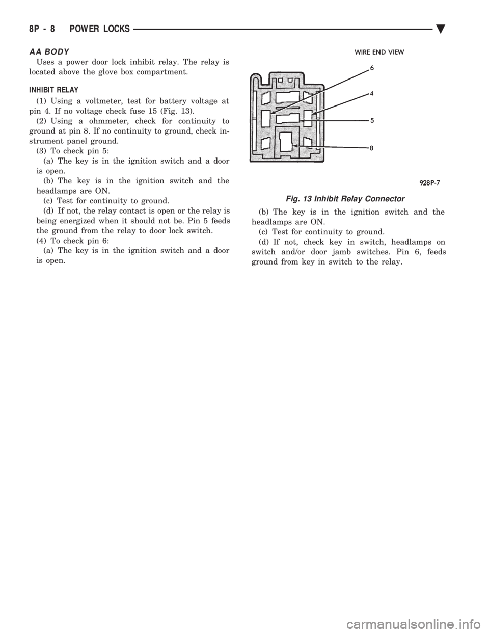
(1) Using a voltmeter, test for battery voltage at
pin 4. If no voltage check fuse 15 (Fig. 13). (2) Using a ohmmeter, check for continuity to
ground at pin 8. If no continuity to ground, check in-
strument panel ground. (3) To check pin 5:(a) The key is in the ignition switch and a door
is open. (b) The key is in the ignition switch and the
headlamps are ON. (c) Test for continuity to ground.
(d) If not, the relay contact is open or the relay is
being energized when it should not be. Pin 5 feeds
the ground from the relay to door lock switch.
(4) To check pin 6: (a) The key is in the ignition switch and a door
is open. (b) The key is in the ignition switch and the
headlamps are ON. (c) Test for continuity to ground.
(d) If not, check key in switch, headlamps on
switch and/or door jamb switches. Pin 6, feeds
ground from key in switch to the relay.
Fig. 13 Inhibit Relay Connector
8P - 8 POWER LOCKS Ä
Page 707 of 2438

POWER SEATS
CONTENTS
page page
ADJUSTER ............................. 3
CIRCUIT BREAKER TEST .................. 1
ENTHUSIAST SEAT ....................... 4
GENERAL INFORMATION .................. 1
HARNESS VOLTAGE TEST ................. 1
HORIZONTAL AND VERTICAL TRANSMISSIONS ....................... 3
MEMORY CONTROL MODULE REPLACEMENT ....................... 19
MOTOR ................................ 3
MOTOR TESTS .......................... 1
POWER MEMORY SEAT, RECLINER AND MIRRORS ............................. 5 POWER MEMORY SEAT, RECLINER AND
MIRRORS DIAGNOSIS ................... 9
POWER RECLINER MECHANISM ........... 18
POWER RECLINER MOTOR AND CABLE ..... 17
RECLINER SWITCH REPLACEMENT ......... 19
RECLINER SWITCH TEST ................. 19
SEAT ASSEMBLY ........................ 3
SWITCH REPLACEMENT REMOVAL .......... 5
SWITCH TEST ........................... 5
SWITCH TEST ........................... 3
TEST PROCEDURES ...................... 6
TEST PROCEDURES ...................... 1
GENERAL INFORMATION
Power seats can be adjusted in six different direc-
tions up, down, forward, back, tilt forward, or tilt
rearward. A three armature permanent magnet reversible mo-
tor is coupled through cables to worm gear box assem-
blies located in the seat tracks, providing the various
seat movements. The electrical circuit is protected by a 30 amp circuit
breaker located on the fuse block.
TEST PROCEDURES
Before any testing is attempted the battery should be
carefully charged and all connections and terminals
cleaned and tightened to insure proper continuity and
grounds. With dome lamp on, apply switch in direction of
failure. If dome lamp dims the seat motor is trying to
work indicating mechanical jamming. If dome lamp
does not dim, then proceed with the following electrical
tests.
CIRCUIT BREAKER TEST
Find correct circuit breaker on fuse block. Pull out
slightly but be sure that circuit breaker terminals still
contact terminals in fuse block. Connect ground wire of
voltmeter to a good ground. With probe of voltmeter
positive wire, check both terminals of circuit breaker
for battery voltage. If only one terminal checks at
battery voltage, circuit breaker is defective and must
be replaced. If neither terminal shows battery voltage,
check for open or shorted circuit to circuit breaker.
HARNESS VOLTAGE TEST
The following test will determine whether or not
voltage is continuous through the body harness to the
switch. (1) Remove power seat switch from mounting posi-
tion and disconnect switch from wiring harness. (2) Connect one lead of test light to ground terminal,
black wire (BK) of center section, and touch other test
light lead to red wire (RD) terminal. (3) If test light comes on, harness to switch is good.
If test light does not come on, perform circuit breaker
test.
MOTOR TESTS
AA BODY
(1) Remove switch from mounting position and dis-
connect from harness. (2) To check the center motor, connect a jumper wire
between pin 5 and pin 3 (Fig. 1). Connect a second
jumper wire between pin 7 and pin 4 If motor does not
operate, reverse the jumpers, pin 5 to pin 4 and pin 7 to
pin 3. If motor still does not operate check wiring
between switch connector and motor assembly. If wir-
ing checks good replace motor assembly. (3) To check the front motor, connect a jumper wire
between pin 5 and pin 1 (Fig. 1). Connect a second
jumper wire between pin 7 and pin 8. If motor does not
operate, reverse the jumpers, pin 5 to pin 8 and pin 7 to
pin 1. If motor still does not operate check wiring
between switch connector and motor assembly. If wir-
ing checks good replace motor assembly.
(4) To check the rear motor, connect a covered jumper
wire between pin 5 and pin 6 (Fig. 1). Connect a second
Ä POWER SEATS 8R - 1
Page 715 of 2438
above. When the control module has finished, it will
return to the normal operating mode after ten sec-
onds if no further switches are activated.The control module will also return to normal op-
erating mode if any manual seat or recliner move-
ment switch is actuated during the ten second
timeout. If the system has found a problem, refer to the ap-
propriate diagnosis condition.
POWER MEMORY SEAT, RECLINER AND
MIRRORS DIAGNOSIS
Before any diagnosis is done on the system, move
the seat switches and listen for relays clicking in the
control module under the seat. If relays can be heard,
the main battery and ground circuits to the control
module as well as the battery circuit to the switches
in the driver's door are good. When checking for voltage or continuity, always
use a volt/ohm meter to get accurate readings. The
seat and recliner switches must be activated to check
for voltage at the seat and recliner motors or at the
input to the control module from the switches. The control module creates a special voltage supply
for the position sensing functions. It also shuts down
after five seconds, in order to check this or any other
voltage being fed back to the control module. A
switch may have to be activated more than once to
verify a voltage reading. The voltage from the con-
trol module that feeds the seat and recliner position
sensing potentiometer, will be between 4.5 to 5 volts.
For simplicity in the diagnosis section, the feed volt-
age will be called 5 volts. On the position sensing
wires, these voltages will always be less than 5 volts
but more than 0 volts. Typically the high level is at
a maximum of about 4.25 volts and the low level can
be as little as 0.1 volts. If any seat or recliner potentiometer or mirror
rheostat position sense wires are crossed, the control
module will not move that part of the system. The
seat or mirror will be in a fault diagnostic mode.
CONDITION: SYSTEM WILL NOT OPERATE.
PROCEDURE
(1) Check for forward/rearward operation of re-
cliner. If not operable, check for an open or loose cir-
cuit breaker mounted in board on the relay bank in
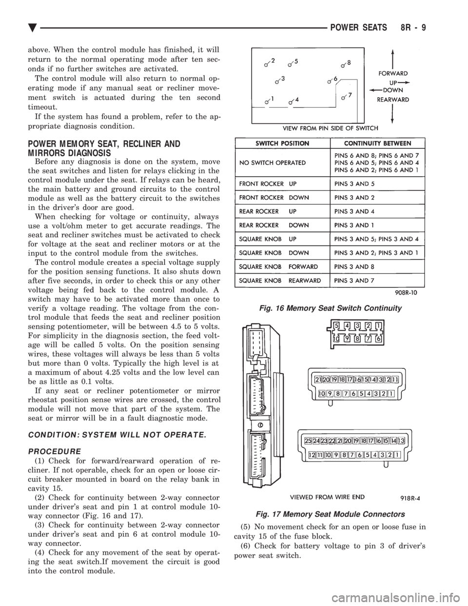
cavity 15. (2) Check for continuity between 2-way connector
under driver's seat and pin 1 at control module 10-
way connector (Fig. 16 and 17). (3) Check for continuity between 2-way connector
under driver's seat and pin 6 at control module 10-
way connector. (4) Check for any movement of the seat by operat-
ing the seat switch.If movement the circuit is good
into the control module. (5) No movement check for an open or loose fuse in
cavity 15 of the fuse block. (6) Check for battery voltage to pin 3 of driver's
power seat switch.
Fig. 16 Memory Seat Switch Continuity
Fig. 17 Memory Seat Module Connectors
Ä POWER SEATS 8R - 9
Page 721 of 2438

(3) Use an ohmmeter to test the wiring between
the door switch and the control module in the driv-
er's seat. The circuits should be disconnected from
their components at each end. Repair the wiring as
required for open circuits, terminal push outs, or bad
crimps. If the circuits are good to the control module
but the function is still missing, replace the control
module.
CONDITION: NO MOVEMENT OF THE SEAT, RELAYS CAN BE HEARD CLICKING WHENTHE SEAT SWITCH IS ACTIVATED.
PROCEDURE
(1) Check for battery voltage and ground at the ap-
propriate pins of the control module 10-way connec-
tor (Fig. 23). If the proper results are not obtained,
replace the control module. If the circuits are correct,
then continue the procedure.
(2) Check for continuity of the motor circuits from
the control module 10-way connector to the left
power seat motor package (Fig. 24). (3) Repair the wiring as required for open circuits,
terminal push outs, or bad crimps. If the circuits are
good but the seat movement direction is still missing,
replace the seat motor package assembly. After re-
placement of the seat motor package, reconnect all wiring connectors and reinstall seat assembly in ve-
hicle. Operate the switches manually to cause maxi-
mum seat movement in all directions. Perform the
memory seat diagnostic self check so the control
module will learn the new soft limits of the assem-
bly.
CONDITION: NO MOVEMENT OF THE MEMORY MIRRORS WHEN THE POWERMIRROR SWITCH IS ACTUATED, MEMORYMIRRORS MOVE DURING RECALL ONLY.
PROCEDURE
(1) Check for battery voltage at pin 1 of the mem-
ory mirror switch 8-way connector in the driver's
door. This battery feed is through a diode package
that is located in the left cowl side area. A grounded
wire on the switch side of the diode would most
likely cause the diode package to open. Solder and
tape the connections if replacement is necessary. The
fuse is in cavity 13 of the fuse block. (2) Check for ground at pin 5 of the memory mir-
ror switch 8-way connector. Repair as needed. (3) Check for continuity of the memory mirror
switch. Refer to the Group 8T, Mirror Switch Test
Procedure and the Continuity.
Fig. 23 Control Module 10-Way Connector Voltage and Ground Test
Fig. 24 Control Module 10-Way Connector to PowerSeat Motor Connector Continuity
Ä POWER SEATS 8R - 15
Page 727 of 2438
POWER WINDOWS
CONTENTS
page page
BENCH REPAIR OF REGULATOR AND MOTOR CONVENTIONAL REGULATORS .......... 5
GEAR AND PINION REPLACEMENT AND LUBRICATION ....................... 3
GENERAL INFORMATION .................. 1
MOTOR REPLACEMENT ................... 7
MOTOR REPLACEMENT CONVENTIONAL REGULATORS ....................... 3
MOTOR REPLACEMENTÐFLEX DRIVE REGULATORS ......................... 5 POWER WINDOW CABLE HOUSING/MOTOR RE-
PLACEMENTÐAC and AY BODIES ........ 7
QUARTER WINDOW MOTOR REPLACEMENTÐ AJ BODY ............................. 9
QUARTER WINDOW REPLACEMENTÐ AJ BODY ............................. 8
WINDOW LIFT MOTOR TEST .............. 1
WINDOW LIFT SWITCH TEST .............. 1
WIRING VOLTAGE TEST .................. 1
GENERAL INFORMATION
Front and rear door window lift motors are of the
permanent magnet type. A positive and negative bat-
tery connection to either of the two motor terminals
will cause the motor to rotate in one direction. Re-
versing current through these same two connections
will cause the motor to rotate in the opposite direc-
tion. Each individual motor is grounded through the
master switch by a black wire attached to the left
cowl panel. It is necessary that the window be free to slide up
and down in the glass channels or tubes and tracks.
If the window is not free to move up and down, the
window lift motor will not be able to move the glass. To determine if the glass is free is to disconnect the
regulator from the glass lift plate, and slide the win-
dow up and down by hand. For conventional arm-sec-
tor regulators, after the lift plate is detached from
the glass, it will slide off the regulator drive arm.
Flex-drive regulators may be detached the same way
or by removing one screw holding the flex rack to the
lift plate drive arm.
WIRING VOLTAGE TEST
The following wiring test determines whether or
not voltage is continuous through the body harness
to switch. After removing switch for testing purposes, care-
fully separate multiple terminal block on wiring har-
ness from switch body. With ignition switch ON
connect one lead of test light to black (or gray) wire
terminal and touch other test light lead to tan wire
terminal. If the test light comes on, the wiring cir-
cuit between the battery and switch is functional. If
light does not come on, check 30 amp main fuse (cir- cuit breaker) or for a broken wire. For wiring, spe-
cific connector type and location, refer to Group 8W,
Wiring Diagrams.
WINDOW LIFT SWITCH TEST
For switch testing, remove the switch from its
mounting. Using an ohmmeter, refer to Window
Switch Continuity Charts to determine if continuity
is correct. If the results are not obtained, replace the
switch. AC and AY Bodies are equipped with an Auto-
Down feature. This feature allows the operator to
lower the driver's window without having to hold the
switch in the down position. The Auto-Down feature
can be activated by pressing the down switch past
the first detent (Stop). To test the auto-down feature, operate the window
in the normal up and down mode. If the window
works correctly in the normal mode, but not in the
auto-down mode, replace the switch. To test the window switch (other than Auto-Down
mode), install a known good switch.
WINDOW LIFT MOTOR TEST
(1) Connect positive (+) lead from a test battery to
either of the two motor terminals. (2) Connect negative (-) lead from test battery to
remaining motor terminal. (3) The motor should now rotate in one direction to
either move window up or down. (a) If window happens to already be in full UP
position and motor is connected so as to rotate in
UP direction no movement will be observed. (b) Likewise, motor connected to DOWN direc-
tion rotation, no movement will be observed if win-
dow is already in full DOWN position.
Ä POWER WINDOWS 8S - 1
Page 738 of 2438
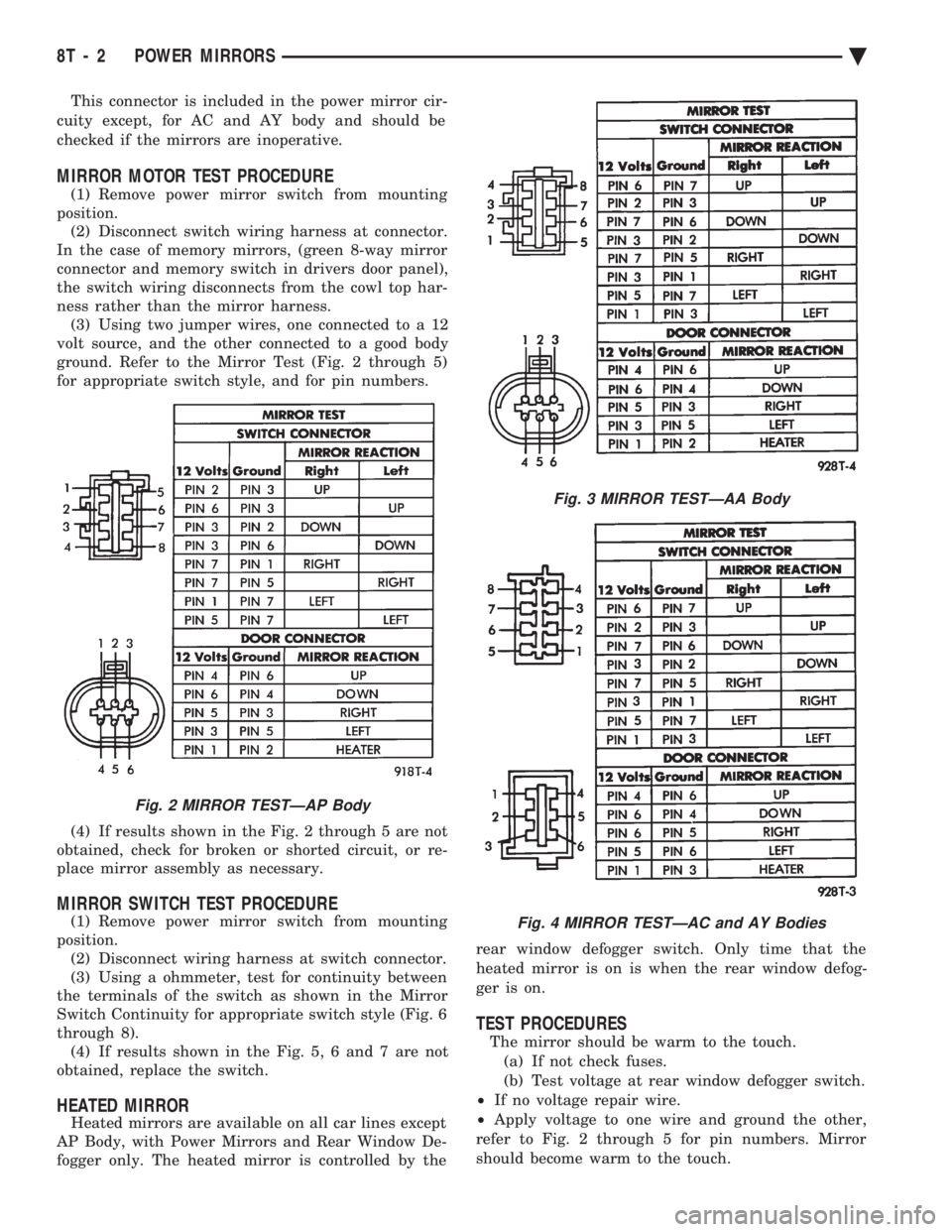
This connector is included in the power mirror cir-
cuity except, for AC and AY body and should be
checked if the mirrors are inoperative.
MIRROR MOTOR TEST PROCEDURE
(1) Remove power mirror switch from mounting
position. (2) Disconnect switch wiring harness at connector.
In the case of memory mirrors, (green 8-way mirror
connector and memory switch in drivers door panel),
the switch wiring disconnects from the cowl top har-
ness rather than the mirror harness. (3) Using two jumper wires, one connected to a 12
volt source, and the other connected to a good body
ground. Refer to the Mirror Test (Fig. 2 through 5)
for appropriate switch style, and for pin numbers.
(4) If results shown in the Fig. 2 through 5 are not
obtained, check for broken or shorted circuit, or re-
place mirror assembly as necessary.
MIRROR SWITCH TEST PROCEDURE
(1) Remove power mirror switch from mounting
position. (2) Disconnect wiring harness at switch connector.
(3) Using a ohmmeter, test for continuity between
the terminals of the switch as shown in the Mirror
Switch Continuity for appropriate switch style (Fig. 6
through 8). (4) If results shown in the Fig. 5, 6 and 7 are not
obtained, replace the switch.
HEATED MIRROR
Heated mirrors are available on all car lines except
AP Body, with Power Mirrors and Rear Window De-
fogger only. The heated mirror is controlled by the rear window defogger switch. Only time that the
heated mirror is on is when the rear window defog-
ger is on.
TEST PROCEDURES
The mirror should be warm to the touch. (a) If not check fuses.
(b) Test voltage at rear window defogger switch.
² If no voltage repair wire.
² Apply voltage to one wire and ground the other,
refer to Fig. 2 through 5 for pin numbers. Mirror
should become warm to the touch.
Fig. 2 MIRROR TESTÐAP Body
Fig. 3 MIRROR TESTÐAA Body
Fig. 4 MIRROR TESTÐAC and AY Bodies
8T - 2 POWER MIRRORS Ä
Page 744 of 2438
(2) The headlamps and parking lamps should turn
ON for about five seconds.
² AUTO MIRROR LED
² DARK LED
² AUTO LAMP LED
² The LED indicators blink for about 5 seconds.
² If the three indicators continue to blink consider-
ably longer than 5 seconds, then the mirror assembly
is defective. (3) The mirror should change to dim state.(a) Place shift selector in reverse (R), with igni-
tion switch ON:
² AUTO MIRROR LED indicator ON
² DARK LED indicator flashing
² Lasting about 15 seconds
(b) The mirror should slowly change to bright
state. (c) If the ignition is not turned OFF within the
15 second time period, the mirror will reset to its
previous setting.
The previous conditions are OK, the mirror is op-
erating properly. If not OK, continue with voltage tests below.
VOLTAGE TEST
To test for voltage insert voltmeter probe into wire
end of connector to contact terminal. Pin 1 ignition voltage (a) Ignition switch OFF, zero volts.
(b) Ignition switch ON, battery voltage.
Pin 2 battery voltage (a) Battery voltage at all times.
(b) No voltage, check 15 amp. fuse.
Pin 3 Ground (a) Continuity to ground.
(b) No voltage
Pin 4 Reverse over-ride (a) Ignition OFF, zero voltage.
(b) Ignition ON shift selector in Reverse (R), bat-
tery voltage. (c) Ignition ON shift selector in any position
other than Reverse (R), zero voltage.
Pin 5 Headlamp relay (a) Battery voltage at all times from headlamp
relay. (b) No battery voltage, test headlamp relay.
Pin 6 Park lamp relay (a) Ignition switch ON, battery voltage feed from
park lamp relay. (b) Ignition switch OFF, zero voltage.
(c) Ignition ON, No battery voltage test park
lamp relay.
If Voltage Test are OK, replace mirror assembly.
If not OK, refer to Wiring Diagrams manual.
8T - 8 POWER MIRRORS Ä