1993 CHEVROLET PLYMOUTH ACCLAIM fuse
[x] Cancel search: fusePage 562 of 2438

CIGAR LIGHTER REPLACEMENT
(1) Remove center bezel assembly (Fig. 23).
(2) Remove center module lower cover or open for-
ward console lid. (3) Unscrew lighter receptacle shell from recepta-
cle and remove from base instrument panel. (4) Disconnect wiring connectors from lighter re-
ceptacle and remove from vehicle. (5) For installation reverse above procedures.
REAR WINDOW DEFOGGER AND/OR FOG LAMP SWITCH REPLACEMENT
(1) Remove center module bezel assembly (Fig. 20).
(2) Remove two switch bezel screws (Fig. 24).
(3) Pull switches and bezel rearward and discon-
nect wiring connector. (4) Remove two switch retaining screws.
(5) Remove switch from bezel.
(6) For installation reverse above procedures.
INTERMITTENT WIPE MODULE REPLACEMENT
(1) Remove lower steering column cover.
(2) Slide intermittent wipe module off of bracket
located on steering column reinforcement (Fig. 25). (3) Disconnect wiring connector from module and
remove module from vehicle. (4) For installation reverse above procedures.
GLOVE BOX LAMP AND SWITCHREPLACEMENT
(1) Disconnect battery and/or pull fuse # 13 before
starting removal procedure. (2) Open glove box door (Fig. 26).
(3) Carefully pry lamp from its mounting surface
with tip of a small screwdriver. (4) Pull lamp from box and disconnect electrical
leads. (5) Remove lamp.
(6) For installation reverse above procedures.
CONSOLETTE ASSEMBLY REPLACEMENT
(1) Remove shifter handle.
(2) Unsnap transmission range indicator bezel or
shift boot bezel from consolette, disconnect wiring
and remove bezel assembly (Fig. 27). (3) Remove two screws from side of armrest.
(4) Remove four caps which cover attaching
screws. (5) Remove four attaching screws.
(6) Lift consolette up and over shift mechanism to
remove. (7) For installation reverse above procedures.
Fig. 24 Rear Window Defogger and Fog Lamp Switch
Fig. 25 Intermittent Wipe Module
Fig. 26 Glove Box Lamp and Switch
8E - 70 INSTRUMENT PANEL AND GAUGES Ä
Page 595 of 2438

² If no short to ground at connector, check speaker
resistance at amplifier connector for an reading of
three to five ohms.
² If resistance is OK, refer to Radio Diagnosis. If ra-
dio checks OK, replace amplifier.
² If resistance is less than three ohms check
speaker. Check across the speaker connector if less
than three ohms replace speaker. If resistance is OK
repair wires
CONDITION: MECHANICAL NOISE DISTORTION
² Check trim for loose parts and speaker attach-
ments for buzzes
² Remove speaker still connected and listen for dis-
tortion. Distortion replace speaker.
CONDITION: ONE SPEAKER NON-OPERATIVE
² Remove output signal connector from amplifier
and check for three to five ohms resistance to the
non-operative speaker. Refer to Fig. 34 for the appro-
priate pin numbers.
² If resistance is less than three ohms, test speaker
for resistance.
² If OK repair wire. If not replace speaker.
CONDITION: ALL SPEAKERS NON-OPERATIVE
²Check radio for being ON, are the display lights
on
² Radio not ON, refer to Radio Diagnosis
² Check Amplifier Connectors and wires for proper
connection
² Check pin 9 and pin 27 for battery voltage
² If voltage OK replace amplifier ²
If pin 27 has battery voltage and pin 9 has 0 volt-
age. Refer to Power Antenna Diagnosis and test volt-
age at antenna relay.
² If pin 9 has battery voltage and pin 27 has 0 volt-
age. Check pin 27 for short to ground.
² If shorted to ground repair wire
² If no short to ground check fuse cavity number 16
for blown fuse.
² If fuse blows again replace amplifier
RELAY/CHOKEÐINFINITY SPEAKER
If the audio system is lacking bass, check for con-
tinuity across the relay and choke connectors. If no
continuity, replace relay/choke assembly (Fig. 35).
LOCATION
(1) AA and AP Bodies, attached to the reinforce-
ment above glove box. (2) AG Body, attached to the dimmer module bay-
onet bracket on the bulkhead behind the glove box.
Fig. 35 Relay/Choke Assembly
Ä AUDIO SYSTEM 8F - 29
Page 597 of 2438
HORNS
CONTENTS
page page
GENERAL INFORMATION .................. 1
HORN SWITCH REPLACEMENT ............ 3 TESTING HORN SYSTEM
................. 1
GENERAL INFORMATION
WARNING: ON VEHICLES EQUIPPED WITH AIR
BAG, SEE GROUP 8M, RESTRAINT SYSTEMS FOR
STEERING WHEEL OR COLUMN REMOVAL PROCE-
DURES.
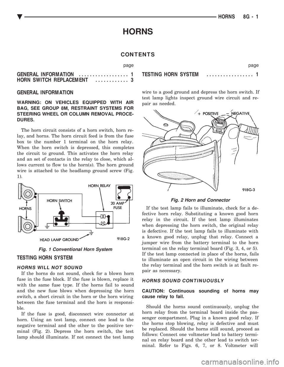
The horn circuit consists of a horn switch, horn re-
lay, and horns. The horn circuit feed is from the fuse
box to the number 1 terminal on the horn relay.
When the horn switch is depressed, this completes
the circuit to ground. This activates the horn relay
and an set of contacts in the relay to close, which al-
lows current to flow to the horn(s). The horn ground
wire is attached to the headlamp ground screw (Fig.
1).
TESTING HORN SYSTEM
HORNS WILL NOT SOUND
If the horns do not sound, check for a blown horn
fuse in the fuse block. If the fuse is blown, replace it
with the same fuse type. If the horns fail to sound
and the new fuse blows when depressing the horn
switch, a short circuit in the horn or the horn wiring
between the fuse terminal and the horn is responsi-
ble. If the fuse is good, disconnect wire connector at
horn. Using an test lamp, connect one lead to the
negative terminal and the other to the positive ter-
minal (Fig. 2). Depress the horn switch, the test
lamp should illuminate. If not connect the test lamp wire to a good ground and depress the horn switch. If
test lamp lights inspect ground wire circuit and re-
pair as needed.
If the test lamp fails to illuminate, check for a de-
fective horn relay. Substituting a known good horn
relay in the circuit. If the test lamp illuminates
when depressing the horn switch, the original relay
is defective. If the test lamp fails to illuminate with
a known good relay, unplug that relay. Connect a
jumper wire from the battery terminal to the horn
terminal on the relay terminal board (Fig. 3, 4, or 5).
If the test lamp connected in place of the horns, fails
to illuminate an open circuit in the wiring between
the relay terminal and the horn switch is at fault re-
pair as necessary.
HORNS SOUND CONTINUOUSLY
CAUTION: Continuous sounding of horns may
cause relay to fail.
Should the horns sound continuously, unplug the
horn relay from the terminal board inside the pas-
senger compartment. Plug in a known good relay. If
the horns stop blowing, relay is defective and must
be replaced. Should the horns still sound, proceed as
follows: Connect one voltmeter lead to battery termi-
nal on relay board and the other lead to switch ter-
minal. Refer to Figs. 6, 7, or 8. Voltmeter will
Fig. 1 Conventional Horn System
Fig. 2 Horn and Connector
Ä HORNS 8G - 1
Page 605 of 2438
INOPERATIVE SYSTEM
If road test verifies an inoperative system with a
correct speedometer operation:
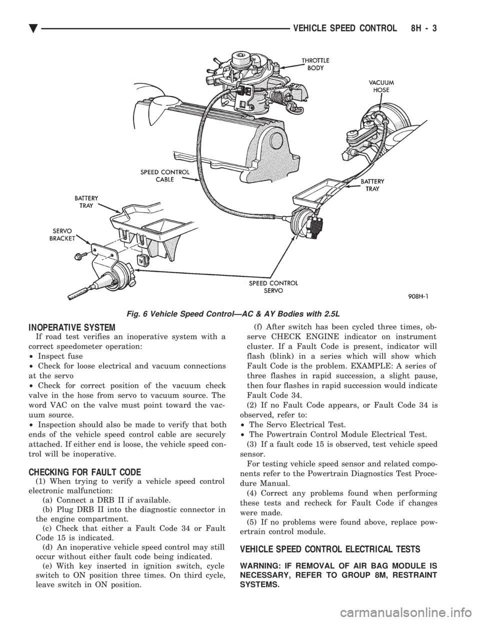
² Inspect fuse
² Check for loose electrical and vacuum connections
at the servo
² Check for correct position of the vacuum check
valve in the hose from servo to vacuum source. The
word VAC on the valve must point toward the vac-
uum source.
² Inspection should also be made to verify that both
ends of the vehicle speed control cable are securely
attached. If either end is loose, the vehicle speed con-
trol will be inoperative.
CHECKING FOR FAULT CODE
(1) When trying to verify a vehicle speed control
electronic malfunction: (a) Connect a DRB II if available.
(b) Plug DRB II into the diagnostic connector in
the engine compartment. (c) Check that either a Fault Code 34 or Fault
Code 15 is indicated. (d) An inoperative vehicle speed control may still
occur without either fault code being indicated. (e) With key inserted in ignition switch, cycle
switch to ON position three times. On third cycle,
leave switch in ON position. (f) After switch has been cycled three times, ob-
serve CHECK ENGINE indicator on instrument
cluster. If a Fault Code is present, indicator will
flash (blink) in a series which will show which
Fault Code is the problem. EXAMPLE: A series of
three flashes in rapid succession, a slight pause,
then four flashes in rapid succession would indicate
Fault Code 34.
(2) If no Fault Code appears, or Fault Code 34 is
observed, refer to:
² The Servo Electrical Test.
² The Powertrain Control Module Electrical Test.
(3) If a fault code 15 is observed, test vehicle speed
sensor. For testing vehicle speed sensor and related compo-
nents refer to the Powertrain Diagnostics Test Proce-
dure Manual. (4) Correct any problems found when performing
these tests and recheck for Fault Code if changes
were made. (5) If no problems were found above, replace pow-
ertrain control module.
VEHICLE SPEED CONTROL ELECTRICAL TESTS
WARNING: IF REMOVAL OF AIR BAG MODULE IS
NECESSARY, REFER TO GROUP 8M, RESTRAINT
SYSTEMS.
Fig. 6 Vehicle Speed ControlÐAC & AY Bodies with 2.5L
Ä VEHICLE SPEED CONTROL 8H - 3
Page 606 of 2438

Electronic vehicle speed control may be tested us-
ing two different methods. One involves use of a
DRB II. If this test method is desired, refer to the
Powertrain Diagnostic Test Procedures for charging
and vehicle speed control manual. The other test method uses a volt/ohm meter and is
described in the following tests. If any information is needed concerning wiring, re-
fer to Group 8W, Wiring Diagrams.
CAUTION: When test probing for voltage or conti-
nuity at electrical connectors, care must be taken
not to damage connector, terminals, or seals. If
these components are damaged, intermittent or
complete system failure may occur.
SERVO ELECTRICAL TESTS
WARNING: ON VEHICLES EQUIPPED WITH AIR-
BAG, SEE GROUP 8M, RESTRAINT SYSTEMS FOR
AIRBAG, STEERING WHEEL OR COLUMN RE-
MOVAL PROCEDURES.
(1) Turn ignition switch to the ON position. With
the vehicle speed control switch in the ON position,
set up a voltmeter to read battery voltage and con-
nect the negative lead to a good chassis ground. (2) Disconnect the four-way connector going to the
servo (Fig. 12). Test pin 2 of the main harness four-
way connector for battery voltage. If not OK go to
step 3. If voltage is OK go to step 4. (3) Perform the following tests.(a) Disconnect the six-way connector at the stop
lamp switch and test pin 1 of the main harness for
battery voltage. If voltage is OK perform the stop
lamp switch test. (b) If the stop lamp switch tests OK; repair wire
between the servo and the stop lamp switch. (c) If no voltage at pin 1 at the 6-way stop lamp
connector, remove the vehicle speed control switch
and disconnect the four-way connector. Test pin 1
of main harness for battery voltage. (d) If voltage is OK perform the vehicle speed
control switch test. (e) If vehicle speed control switch is OK, test
continuity across the clockspring. (f) If clockspring OK, repair as required, wire be-
tween stop lamp switch and clockspring. (g) If no voltage at pin 1 of the 4-way vehicle
speed control switch connector.
² Test for battery voltage between the ignition and
the fuse
² If voltage OK, check fuse
² If fuse OK, repair wire between fuse and clock-
spring
Fig. 7 Vehicle Speed ControlÐAC & AY Bodies with 3.0L
8H - 4 VEHICLE SPEED CONTROL Ä
Page 621 of 2438
WINDSHIELD WIPER AND WASHER SYSTEMS
CONTENTS
page page
GENERAL WIPER INFORMATION ........... 1
INTERMITTENT WINDSHIELD WIPER MOTOR AND SWITCH SERVICE PROCEDURES .... 12
WINDSHIELD WASHERS ................. 17 WINDSHIELD WIPER BLADE AND ARM SERVICE
PROCEDURES ......................... 1
WINDSHIELD WIPER MOTOR AND LINKAGE ASSEMBLY SERVICE PROCEDURES ....... 3
GENERAL WIPER INFORMATION
WARNING: ON VEHICLES EQUIPPED WITH AIR-
BAG, SEE GROUP 8M, RESTRAINT SYSTEMS FOR
STEERING WHEEL OR COLUMN REMOVAL PROCE-
DURES.
The windshield wipers can be operated with the
windshield wiper switch only when the ignition
switch is in the ACCESSORY or IGNITION position.
A fuse, located in the fuse block, protects the cir-
cuitry of the wiper system and the vehicle. The wiper motor has permanent magnet fields. The speeds are determined by current flow to the appro-
priate set of brushes. The intermittent wipe system, in addition to low
and high speed, has a delay mode. The delay mode
has a range of 2 to 15 seconds. This is accomplished
by a variable resistor in the wiper switch and is con-
trolled electrically by a relay. The wiper system completes the wipe cycle when
the switch is turned OFF. The blades park in the
lowest portion of the wipe pattern.
WINDSHIELD WIPER BLADE AND ARM SERVICE PROCEDURES
WIPER BLADES
Wiper blades, exposed to the weather for a long pe-
riod of time, tend to lose their wiping effectiveness.
Periodic cleaning of the wiper blade is suggested to
remove the accumulation of salt and road film. The
wiper blades, arms, and windshield should be cleaned
with a sponge or cloth and a mild detergent or nona-
brasive cleaner. If the blades continue to streak or
smear, they should be replaced.
WIPER BLADE ELEMENT CHANGE
(1) Turn wiper switch ON, position blades to a con-
venient place by turning the ignition switch ON and
OFF. (2) Lift wiper arm to raise blade off glass.
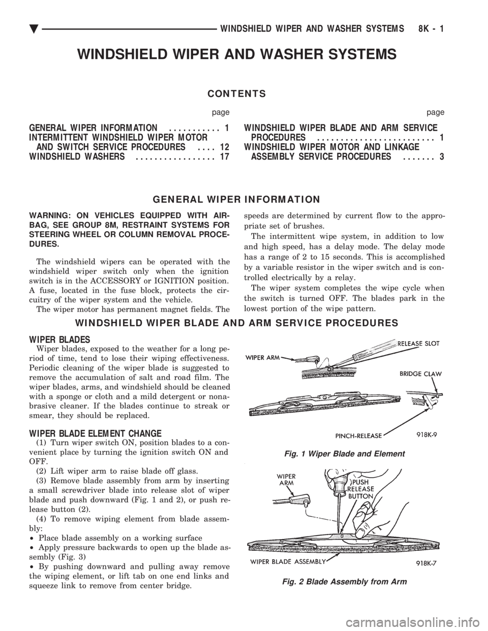
(3) Remove blade assembly from arm by inserting
a small screwdriver blade into release slot of wiper
blade and push downward (Fig. 1 and 2), or push re-
lease button (2). (4) To remove wiping element from blade assem-
bly:
² Place blade assembly on a working surface
² Apply pressure backwards to open up the blade as-
sembly (Fig. 3)
² By pushing downward and pulling away remove
the wiping element, or lift tab on one end links and
squeeze link to remove from center bridge.
Fig. 1 Wiper Blade and Element
Fig. 2 Blade Assembly from Arm
Ä WINDSHIELD WIPER AND WASHER SYSTEMS 8K - 1
Page 623 of 2438
(3) Secure arm to pivot with attaching nut and
tighten 17 to 22 N Im (155 to 195 in. lbs.) torque.
(4) Close head cover and remove pin from arm pin
hole.
WIPER ARM ADJUSTMENT
FRONT ARM ADJUSTMENT
(1) Cycle the wiper motor into the PARK position.
(2) Check the tips of the blades in blackout area.
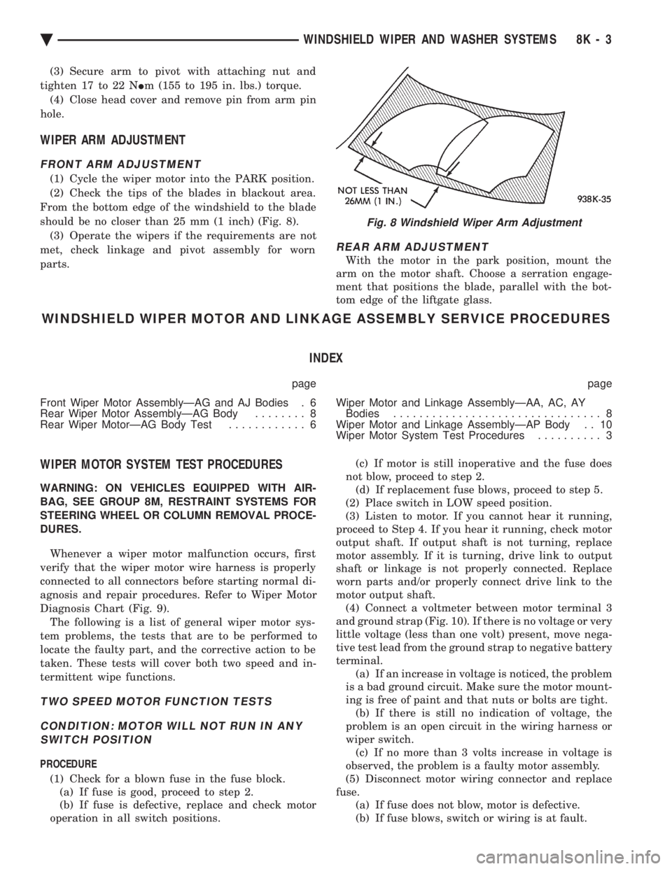
From the bottom edge of the windshield to the blade
should be no closer than 25 mm (1 inch) (Fig. 8). (3) Operate the wipers if the requirements are not
met, check linkage and pivot assembly for worn
parts.
REAR ARM ADJUSTMENT
With the motor in the park position, mount the
arm on the motor shaft. Choose a serration engage-
ment that positions the blade, parallel with the bot-
tom edge of the liftgate glass.
WINDSHIELD WIPER MOTOR AND LINKAGE ASSEMBLY SERVICE PROCEDURES
INDEX
page page
Front Wiper Motor AssemblyÐAG and AJ Bodies . 6
Rear Wiper Motor AssemblyÐAG Body ........ 8
Rear Wiper MotorÐAG Body Test ............ 6 Wiper Motor and Linkage AssemblyÐAA, AC, AY
Bodies ................................ 8
Wiper Motor and Linkage AssemblyÐAP Body . . 10
Wiper Motor System Test Procedures .......... 3
WIPER MOTOR SYSTEM TEST PROCEDURES
WARNING: ON VEHICLES EQUIPPED WITH AIR-
BAG, SEE GROUP 8M, RESTRAINT SYSTEMS FOR
STEERING WHEEL OR COLUMN REMOVAL PROCE-
DURES.
Whenever a wiper motor malfunction occurs, first
verify that the wiper motor wire harness is properly
connected to all connectors before starting normal di-
agnosis and repair procedures. Refer to Wiper Motor
Diagnosis Chart (Fig. 9). The following is a list of general wiper motor sys-
tem problems, the tests that are to be performed to
locate the faulty part, and the corrective action to be
taken. These tests will cover both two speed and in-
termittent wipe functions.
TWO SPEED MOTOR FUNCTION TESTS
CONDITION: MOTOR WILL NOT RUN IN ANY SWITCH POSITION
PROCEDURE
(1) Check for a blown fuse in the fuse block. (a) If fuse is good, proceed to step 2.
(b) If fuse is defective, replace and check motor
operation in all switch positions. (c) If motor is still inoperative and the fuse does
not blow, proceed to step 2. (d) If replacement fuse blows, proceed to step 5.
(2) Place switch in LOW speed position.
(3) Listen to motor. If you cannot hear it running,
proceed to Step 4. If you hear it running, check motor
output shaft. If output shaft is not turning, replace
motor assembly. If it is turning, drive link to output
shaft or linkage is not properly connected. Replace
worn parts and/or properly connect drive link to the
motor output shaft. (4) Connect a voltmeter between motor terminal 3
and ground strap (Fig. 10). If there is no voltage or very
little voltage (less than one volt) present, move nega-
tive test lead from the ground strap to negative battery
terminal. (a) If an increase in voltage is noticed, the problem
is a bad ground circuit. Make sure the motor mount-
ing is free of paint and that nuts or bolts are tight. (b) If there is still no indication of voltage, the
problem is an open circuit in the wiring harness or
wiper switch. (c) If no more than 3 volts increase in voltage is
observed, the problem is a faulty motor assembly.
(5) Disconnect motor wiring connector and replace
fuse. (a) If fuse does not blow, motor is defective.
(b) If fuse blows, switch or wiring is at fault.
Fig. 8 Windshield Wiper Arm Adjustment
Ä WINDSHIELD WIPER AND WASHER SYSTEMS 8K - 3
Page 626 of 2438
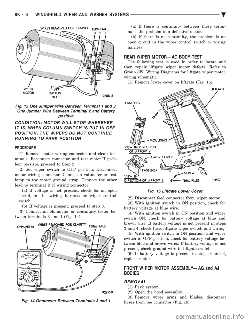
CONDITION: MOTOR WILL STOP WHEREVER IT IS, WHEN COLUMN SWITCH IS PUT IN OFFPOSITION. THE WIPERS DO NOT CONTINUERUNNING TO PARK POSITION
PROCEDURE
(1) Remove motor wiring connector and clean ter-
minals. Reconnect connector and test motor.If prob-
lem persists, proceed to Step 2. (2) Set wiper switch to OFF position. Disconnect
motor wiring connector. Connect a voltmeter or test
lamp to the motor ground strap. Connect the other
lead to terminal 2 of wiring connector. (a) If voltage is not present, check for an open
circuit in the wiring harness or wiper control
switch. (b) If voltage is present, proceed to step 3.
(3) Connect an ohmmeter or continuity tester be-
tween terminals 3 and 1 (Fig. 14). (a) If there is continuity between these termi-
nals, the problem is a defective motor. (b) If there is no continuity, the problem is an
open circuit in the wiper control switch or wiring
harness.
REAR WIPER MOTORÐAG BODY TEST
The following test is used in order to locate and
then repair liftgate wiper motor defects. Refer to
Group 8W, Wiring Diagrams for liftgate wiper motor
wiring schematic. (1) Remove lower cover on liftgate (Fig. 15).
(2) Disconnect feed connector from wiper motor.
(3) With ignition switch in ON position, check for
battery voltage at blue wire. (4) With ignition switch in ON position and wiper
switch ON, check for battery voltage at blue and
brown wire. If battery voltage is not present in steps
3 and 4, check fuse, liftgate wiper switch and wiring. (5) With ignition switch in ON position, and wiper
switch in OFF position, check for battery voltage be-
tween blue and brown wires. If battery voltage is not
present, check ground wire to liftgate switch. (6) If battery voltage is present in steps 3 and 4,
replace motor.
FRONT WIPER MOTOR ASSEMBLYÐAG and AJ
BODIES
REMOVAL
(1) Park system.
(2) Open the hood assembly.
(3) Remove wiper arms and blades, disconnect
hoses from tee connector (Fig. 16).
Fig. 13 One Jumper Wire Between Terminal 1 and 3. One Jumper Wire Between Terminal 2 and Battery positive
Fig. 14 Ohmmeter Between Terminals 3 and 1
Fig. 15 Liftgate Lower Cover
8K - 6 WINDSHIELD WIPER AND WASHER SYSTEMS Ä