1993 CHEVROLET PLYMOUTH ACCLAIM wheel bolts
[x] Cancel search: wheel boltsPage 1726 of 2438
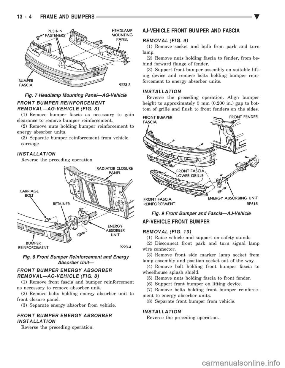
FRONT BUMPER REINFORCEMENT REMOVALÐAG-VEHICLE (FIG. 8)
(1) Remove bumper fascia as necessary to gain
clearance to remove bumper reinforcement. (2) Remove nuts holding bumper reinforcement to
energy absorber units. (3) Separate bumper reinforcement from vehicle.
carriage
INSTALLATION
Reverse the preceding operation
FRONT BUMPER ENERGY ABSORBERREMOVALÐAG-VEHICLE (FIG. 8)
(1) Remove front fascia and bumper reinforcement
as necessary to remove absorber unit. (2) Remove bolts holding energy absorber unit to
front closure panel. (3) Separate energy absorber from vehicle.
FRONT BUMPER ENERGY ABSORBERINSTALLATION
Reverse the preceding operation.
AJ-VEHICLE FRONT BUMPER AND FASCIA
REMOVAL (FIG. 9)
(1) Remove socket and bulb from park and turn
lamp. (2) Remove nuts holding fascia to fender, from be-
hind forward flange of fender. (3) Support front bumper assembly on suitable lift-
ing device and remove bolts holding bumper rein-
forcement to energy absorber units.
INSTALLATION
Reverse the preceding operation. Align bumper
height to approximately 5 mm (0.200 in.) gap to bot-
tom of grille and flush to front fenders on the sides.
AP-VEHICLE FRONT BUMPER
REMOVAL (FIG. 10)
(1) Raise vehicle and support on safety stands.
(2) Disconnect front park and turn signal lamp
wire connector. (3) Remove front side marker lamp socket from
lamp assembly and position socket out of the way. (4) Remove bolt holding front bumper fascia to
wheelhouse splash shield. (5) Remove nuts holding fascia to front fender.
(6) Support front bumper on lifting device.
(7) Remove bolts holding front bumper reinforce-
ment to energy absorber units. (8) Separate front bumper from vehicle.
INSTALLATION
Reverse the preceding operation.
Fig. 7 Headlamp Mounting PanelÐAG-Vehicle
Fig. 8 Front Bumper Reinforcement and Energy Absorber UnitÐ
Fig. 9 Front Bumper and FasciaÐAJ-Vehicle
13 - 4 FRAME AND BUMPERS Ä
Page 1727 of 2438
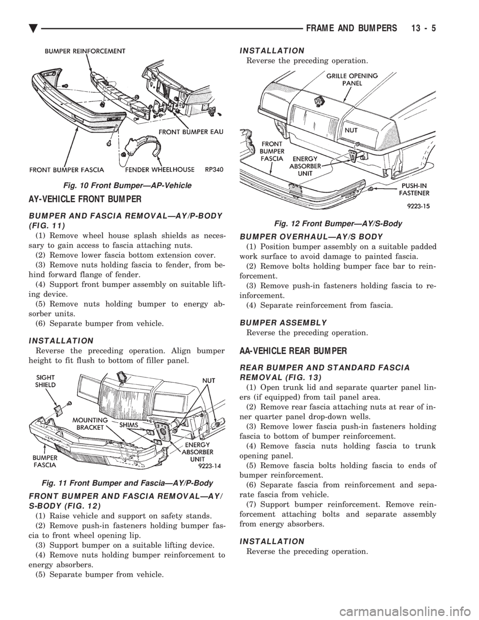
AY-VEHICLE FRONT BUMPER
BUMPER AND FASCIA REMOVALÐAY/P-BODY (FIG. 11)
(1) Remove wheel house splash shields as neces-
sary to gain access to fascia attaching nuts. (2) Remove lower fascia bottom extension cover.
(3) Remove nuts holding fascia to fender, from be-
hind forward flange of fender. (4) Support front bumper assembly on suitable lift-
ing device. (5) Remove nuts holding bumper to energy ab-
sorber units. (6) Separate bumper from vehicle.
INSTALLATION
Reverse the preceding operation. Align bumper
height to fit flush to bottom of filler panel.
FRONT BUMPER AND FASCIA REMOVALÐAY/ S-BODY (FIG. 12)
(1) Raise vehicle and support on safety stands.
(2) Remove push-in fasteners holding bumper fas-
cia to front wheel opening lip. (3) Support bumper on a suitable lifting device.
(4) Remove nuts holding bumper reinforcement to
energy absorbers. (5) Separate bumper from vehicle.
INSTALLATION
Reverse the preceding operation.
BUMPER OVERHAULÐAY/S BODY
(1) Position bumper assembly on a suitable padded
work surface to avoid damage to painted fascia. (2) Remove bolts holding bumper face bar to rein-
forcement. (3) Remove push-in fasteners holding fascia to re-
inforcement. (4) Separate reinforcement from fascia.
BUMPER ASSEMBLY
Reverse the preceding operation.
AA-VEHICLE REAR BUMPER
REAR BUMPER AND STANDARD FASCIAREMOVAL (FIG. 13)
(1) Open trunk lid and separate quarter panel lin-
ers (if equipped) from tail panel area. (2) Remove rear fascia attaching nuts at rear of in-
ner quarter panel drop-down wells. (3) Remove lower fascia push-in fasteners holding
fascia to bottom of bumper reinforcement. (4) Remove fascia nuts holding fascia to trunk
opening panel. (5) Remove fascia bolts holding fascia to ends of
bumper reinforcement. (6) Separate fascia from reinforcement and sepa-
rate fascia from vehicle. (7) Support bumper reinforcement. Remove rein-
forcement attaching bolts and separate assembly
from energy absorbers.
INSTALLATION
Reverse the preceding operation.
Fig. 10 Front BumperÐAP-Vehicle
Fig. 11 Front Bumper and FasciaÐAY/P-Body
Fig. 12 Front BumperÐAY/S-Body
Ä FRAME AND BUMPERS 13 - 5
Page 1728 of 2438
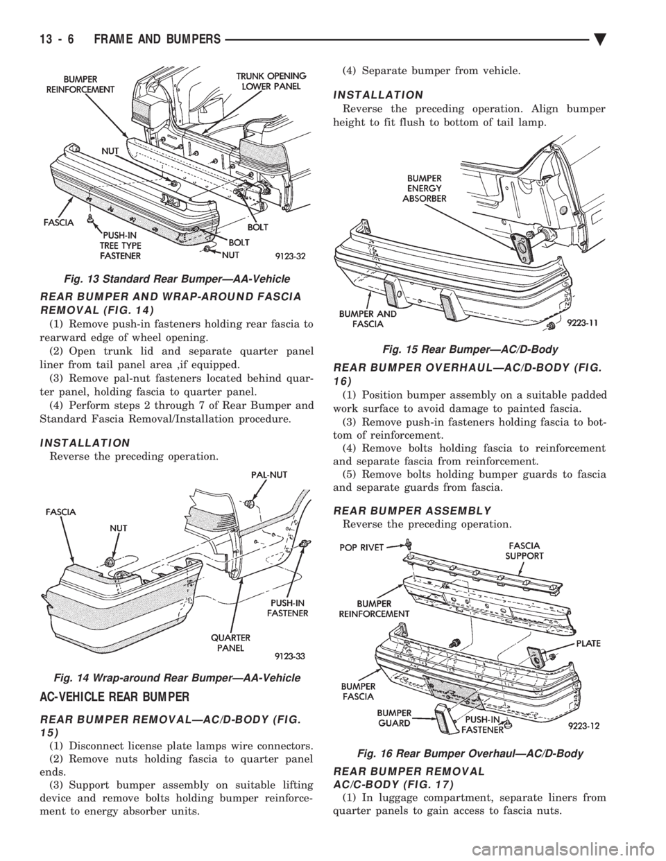
REAR BUMPER AND WRAP-AROUND FASCIA REMOVAL (FIG. 14)
(1) Remove push-in fasteners holding rear fascia to
rearward edge of wheel opening. (2) Open trunk lid and separate quarter panel
liner from tail panel area ,if equipped. (3) Remove pal-nut fasteners located behind quar-
ter panel, holding fascia to quarter panel. (4) Perform steps 2 through 7 of Rear Bumper and
Standard Fascia Removal/Installation procedure.
INSTALLATION
Reverse the preceding operation.
AC-VEHICLE REAR BUMPER
REAR BUMPER REMOVALÐAC/D-BODY (FIG. 15)
(1) Disconnect license plate lamps wire connectors.
(2) Remove nuts holding fascia to quarter panel
ends. (3) Support bumper assembly on suitable lifting
device and remove bolts holding bumper reinforce-
ment to energy absorber units. (4) Separate bumper from vehicle.
INSTALLATION
Reverse the preceding operation. Align bumper
height to fit flush to bottom of tail lamp.
REAR BUMPER OVERHAULÐAC/D-BODY (FIG. 16)
(1) Position bumper assembly on a suitable padded
work surface to avoid damage to painted fascia. (3) Remove push-in fasteners holding fascia to bot-
tom of reinforcement. (4) Remove bolts holding fascia to reinforcement
and separate fascia from reinforcement. (5) Remove bolts holding bumper guards to fascia
and separate guards from fascia.
REAR BUMPER ASSEMBLY
Reverse the preceding operation.
REAR BUMPER REMOVAL AC/C-BODY (FIG. 17)
(1) In luggage compartment, separate liners from
quarter panels to gain access to fascia nuts.
Fig. 13 Standard Rear BumperÐAA-Vehicle
Fig. 14 Wrap-around Rear BumperÐAA-Vehicle
Fig. 15 Rear BumperÐAC/D-Body
Fig. 16 Rear Bumper OverhaulÐAC/D-Body
13 - 6 FRAME AND BUMPERS Ä
Page 1729 of 2438
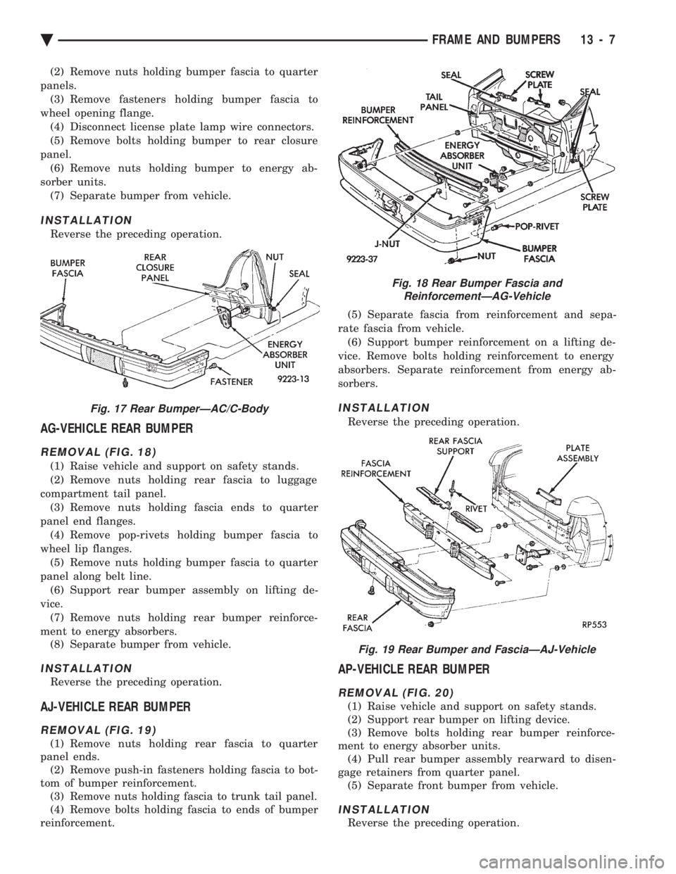
(2) Remove nuts holding bumper fascia to quarter
panels. (3) Remove fasteners holding bumper fascia to
wheel opening flange. (4) Disconnect license plate lamp wire connectors.
(5) Remove bolts holding bumper to rear closure
panel. (6) Remove nuts holding bumper to energy ab-
sorber units. (7) Separate bumper from vehicle.
INSTALLATION
Reverse the preceding operation.
AG-VEHICLE REAR BUMPER
REMOVAL (FIG. 18)
(1) Raise vehicle and support on safety stands.
(2) Remove nuts holding rear fascia to luggage
compartment tail panel. (3) Remove nuts holding fascia ends to quarter
panel end flanges. (4) Remove pop-rivets holding bumper fascia to
wheel lip flanges. (5) Remove nuts holding bumper fascia to quarter
panel along belt line. (6) Support rear bumper assembly on lifting de-
vice. (7) Remove nuts holding rear bumper reinforce-
ment to energy absorbers. (8) Separate bumper from vehicle.
INSTALLATION
Reverse the preceding operation.
AJ-VEHICLE REAR BUMPER
REMOVAL (FIG. 19)
(1) Remove nuts holding rear fascia to quarter
panel ends. (2) Remove push-in fasteners holding fascia to bot-
tom of bumper reinforcement. (3) Remove nuts holding fascia to trunk tail panel.
(4) Remove bolts holding fascia to ends of bumper
reinforcement. (5) Separate fascia from reinforcement and sepa-
rate fascia from vehicle. (6) Support bumper reinforcement on a lifting de-
vice. Remove bolts holding reinforcement to energy
absorbers. Separate reinforcement from energy ab-
sorbers.
INSTALLATION
Reverse the preceding operation.
AP-VEHICLE REAR BUMPER
REMOVAL (FIG. 20)
(1) Raise vehicle and support on safety stands.
(2) Support rear bumper on lifting device.
(3) Remove bolts holding rear bumper reinforce-
ment to energy absorber units. (4) Pull rear bumper assembly rearward to disen-
gage retainers from quarter panel. (5) Separate front bumper from vehicle.
INSTALLATION
Reverse the preceding operation.
Fig. 17 Rear BumperÐAC/C-Body
Fig. 18 Rear Bumper Fascia and ReinforcementÐAG-Vehicle
Fig. 19 Rear Bumper and FasciaÐAJ-Vehicle
Ä FRAME AND BUMPERS 13 - 7
Page 1730 of 2438
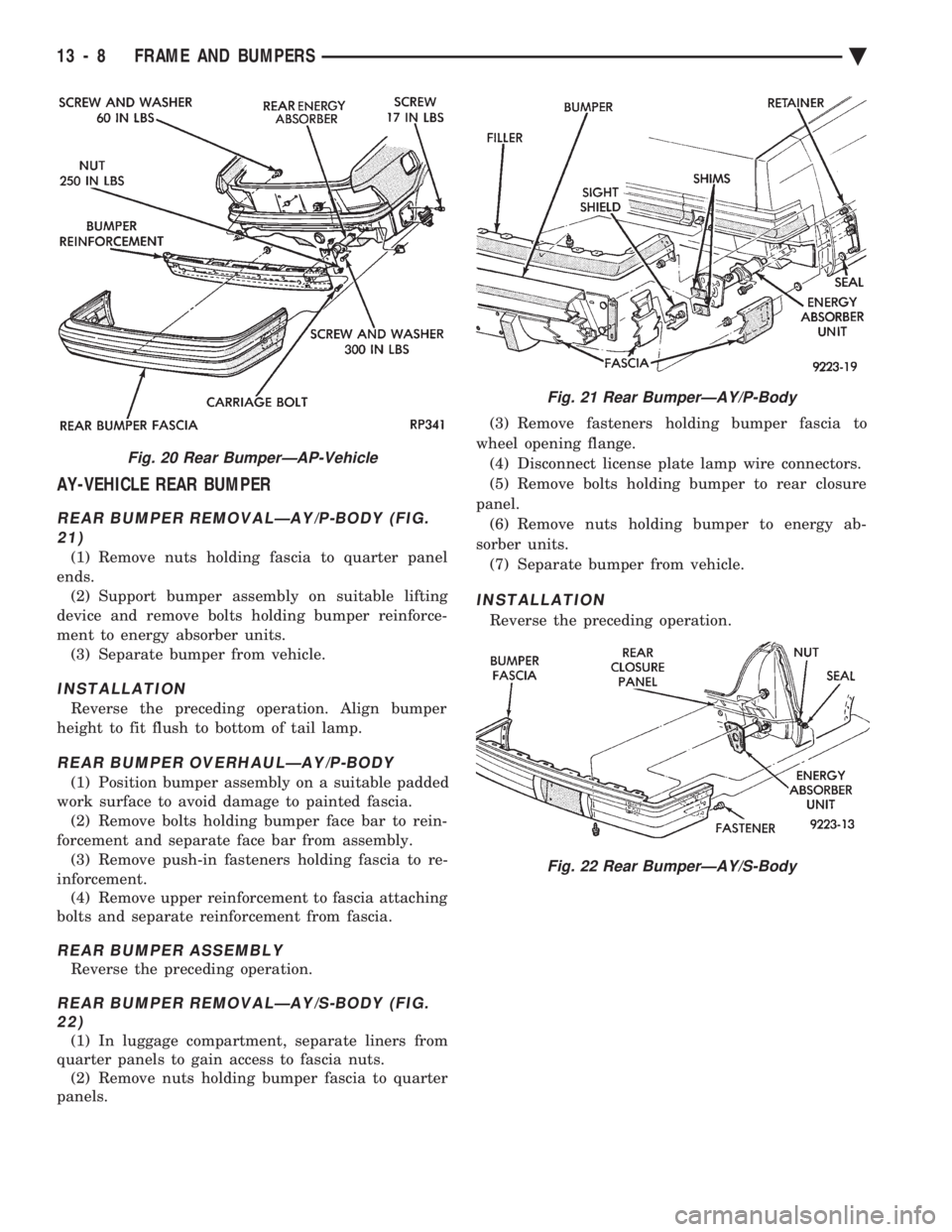
AY-VEHICLE REAR BUMPER
REAR BUMPER REMOVALÐAY/P-BODY (FIG. 21)
(1) Remove nuts holding fascia to quarter panel
ends. (2) Support bumper assembly on suitable lifting
device and remove bolts holding bumper reinforce-
ment to energy absorber units. (3) Separate bumper from vehicle.
INSTALLATION
Reverse the preceding operation. Align bumper
height to fit flush to bottom of tail lamp.
REAR BUMPER OVERHAULÐAY/P-BODY
(1) Position bumper assembly on a suitable padded
work surface to avoid damage to painted fascia. (2) Remove bolts holding bumper face bar to rein-
forcement and separate face bar from assembly. (3) Remove push-in fasteners holding fascia to re-
inforcement. (4) Remove upper reinforcement to fascia attaching
bolts and separate reinforcement from fascia.
REAR BUMPER ASSEMBLY
Reverse the preceding operation.
REAR BUMPER REMOVALÐAY/S-BODY (FIG. 22)
(1) In luggage compartment, separate liners from
quarter panels to gain access to fascia nuts. (2) Remove nuts holding bumper fascia to quarter
panels. (3) Remove fasteners holding bumper fascia to
wheel opening flange. (4) Disconnect license plate lamp wire connectors.
(5) Remove bolts holding bumper to rear closure
panel. (6) Remove nuts holding bumper to energy ab-
sorber units. (7) Separate bumper from vehicle.
INSTALLATION
Reverse the preceding operation.
Fig. 20 Rear BumperÐAP-Vehicle
Fig. 21 Rear BumperÐAY/P-Body
Fig. 22 Rear BumperÐAY/S-Body
13 - 8 FRAME AND BUMPERS Ä
Page 1739 of 2438
CROSSMEMBER
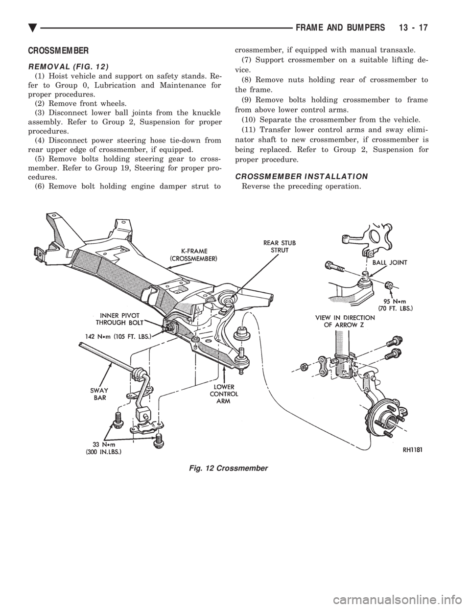
REMOVAL (FIG. 12)
(1) Hoist vehicle and support on safety stands. Re-
fer to Group 0, Lubrication and Maintenance for
proper procedures. (2) Remove front wheels.
(3) Disconnect lower ball joints from the knuckle
assembly. Refer to Group 2, Suspension for proper
procedures. (4) Disconnect power steering hose tie-down from
rear upper edge of crossmember, if equipped. (5) Remove bolts holding steering gear to cross-
member. Refer to Group 19, Steering for proper pro-
cedures. (6) Remove bolt holding engine damper strut to crossmember, if equipped with manual transaxle.
(7) Support crossmember on a suitable lifting de-
vice. (8) Remove nuts holding rear of crossmember to
the frame. (9) Remove bolts holding crossmember to frame
from above lower control arms. (10) Separate the crossmember from the vehicle.
(11) Transfer lower control arms and sway elimi-
nator shaft to new crossmember, if crossmember is
being replaced. Refer to Group 2, Suspension for
proper procedure.
CROSSMEMBER INSTALLATION
Reverse the preceding operation.
Fig. 12 Crossmember
Ä FRAME AND BUMPERS 13 - 17
Page 1929 of 2438
INSTALL
(1) Install power steering pressure switch into fit-
ting on power steering pressure hose by hand until
fully seated. Then torque power steering pressure
switch to 12 N Im (106 in. lbs.).
(2) Install vehicle wiring harness connector onto
power steering pressure switch. Be sure latch on wir-
ing harness connector is fully engaged with locking
tab on power steering pressure switch.
CAUTION: Do not use automatic transmission fluid
in power steering system. Only use Mopar T, Power
Steering Fluid, or equivalent.
(3) Fill power steering pump reservoir to correct
fluid level. (4) Connect negative cable back on negative post of
battery. (5) Start engine and turn steering wheel several
times from stop to stop to bleed air from fluid in sys-
tem. Stop engine, check fluid level, and inspect sys-
tem for leaks. See Checking Fluid Level.
POWER STEERING HOSES
Service all power steering hoses with the vehicle
raised on a hoist. Cap all open ends of hoses, power
steering pump fittings and steering gear ports to pre-
vent entry of foreign material into the components.
WARNING: POWER STEERING OIL, ENGINE PARTS
AND EXHAUST SYSTEM MAY BE EXTREMELY HOT
IF ENGINE HAS BEEN RUNNING. DO NOT START
ENGINE WITH ANY LOOSE OR DISCONNECTED
HOSES. DO NOT ALLOW HOSES TO TOUCH HOT
EXHAUST MANIFOLD OR CATALYST.
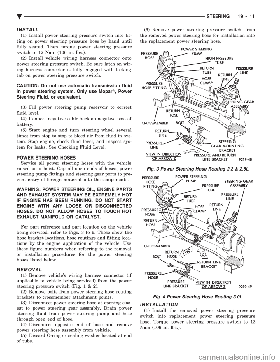
For part reference and part location on the vehicle
being serviced, refer to Figs. 3 to 6. These show the
hose bracket locations, hose routings and fitting loca-
tions by the engine application of the vehicle. Use
these figure numbers when referring to the removal
or installation procedures for the power steering
hoses listed below.
REMOVAL
(1) Remove vehicle's wiring harness connector (if
applicable to vehicle being serviced) from the power
steering pressure switch (Fig .1&2).
(2) Remove bolts from power steering hose routing
brackets to crossmember attachment points. (3) Disconnect power steering hose at opening clos-
est to power steering gear assembly. Drain power
steering fluid from power steering pump and hose
through open end of hose. (4) Disconnect opposite end of hose and remove
power steering hose assembly from vehicle. (5) Discard O-ring or sealing washer located at end
of tube. (6) Remove power steering pressure switch, from
the removed power steering hose for installation into
the replacement power steering hose.
INSTALLATION
(1) Install the removed power steering pressure
switch into replacement power steering pressure
hose. Torque power steering pressure switch to 12
N Im (106 in. lbs.).
Fig. 3 Power Steering Hose Routing 2.2 & 2.5L
Fig. 4 Power Steering Hose Routing 3.0L
Ä STEERING 19 - 11
Page 1932 of 2438
(10) Connect negative cable back on negative post
of battery. (11) Start engine and turn steering wheel several
times from stop to stop to bleed air from fluid in sys-
tem. Stop engine, check fluid level, and inspect sys-
tem for leaks. See Checking Fluid Level.
3.0 LITER
REMOVE
(1) REMOVE THE (-) NEGATIVE BATTERY CA-
BLE FROM THE BATTERY AND ISOLATE CA-
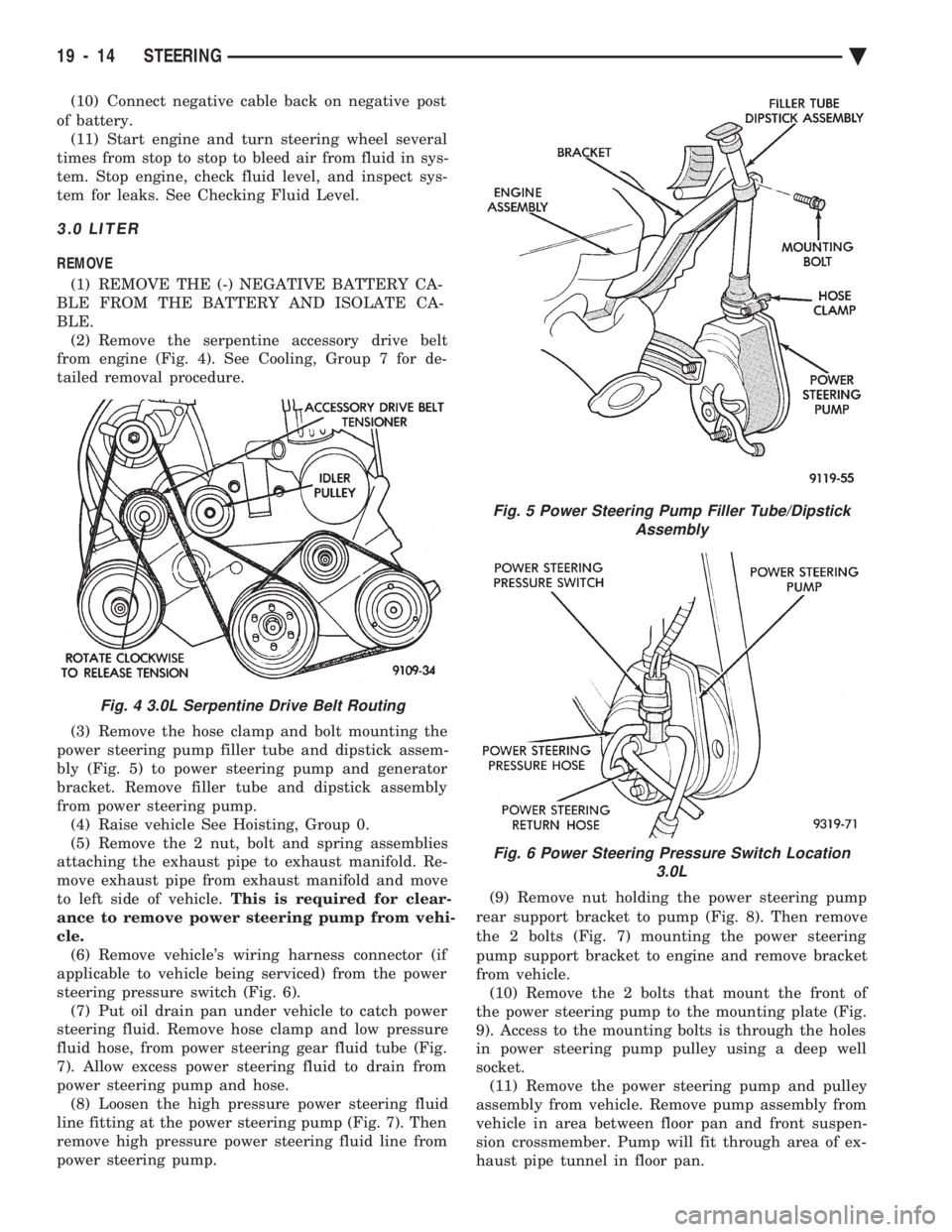
BLE. (2) Remove the serpentine accessory drive belt
from engine (Fig. 4). See Cooling, Group 7 for de-
tailed removal procedure.
(3) Remove the hose clamp and bolt mounting the
power steering pump filler tube and dipstick assem-
bly (Fig. 5) to power steering pump and generator
bracket. Remove filler tube and dipstick assembly
from power steering pump. (4) Raise vehicle See Hoisting, Group 0.
(5) Remove the 2 nut, bolt and spring assemblies
attaching the exhaust pipe to exhaust manifold. Re-
move exhaust pipe from exhaust manifold and move
to left side of vehicle. This is required for clear-
ance to remove power steering pump from vehi-
cle. (6) Remove vehicle's wiring harness connector (if
applicable to vehicle being serviced) from the power
steering pressure switch (Fig. 6). (7) Put oil drain pan under vehicle to catch power
steering fluid. Remove hose clamp and low pressure
fluid hose, from power steering gear fluid tube (Fig.
7). Allow excess power steering fluid to drain from
power steering pump and hose. (8) Loosen the high pressure power steering fluid
line fitting at the power steering pump (Fig. 7). Then
remove high pressure power steering fluid line from
power steering pump. (9) Remove nut holding the power steering pump
rear support bracket to pump (Fig. 8). Then remove
the 2 bolts (Fig. 7) mounting the power steering
pump support bracket to engine and remove bracket
from vehicle. (10) Remove the 2 bolts that mount the front of
the power steering pump to the mounting plate (Fig.
9). Access to the mounting bolts is through the holes
in power steering pump pulley using a deep well
socket. (11) Remove the power steering pump and pulley
assembly from vehicle. Remove pump assembly from
vehicle in area between floor pan and front suspen-
sion crossmember. Pump will fit through area of ex-
haust pipe tunnel in floor pan.
Fig. 4 3.0L Serpentine Drive Belt Routing
Fig. 5 Power Steering Pump Filler Tube/Dipstick Assembly
Fig. 6 Power Steering Pressure Switch Location 3.0L
19 - 14 STEERING Ä