1993 CHEVROLET PLYMOUTH ACCLAIM wheel bolts
[x] Cancel search: wheel boltsPage 2009 of 2438
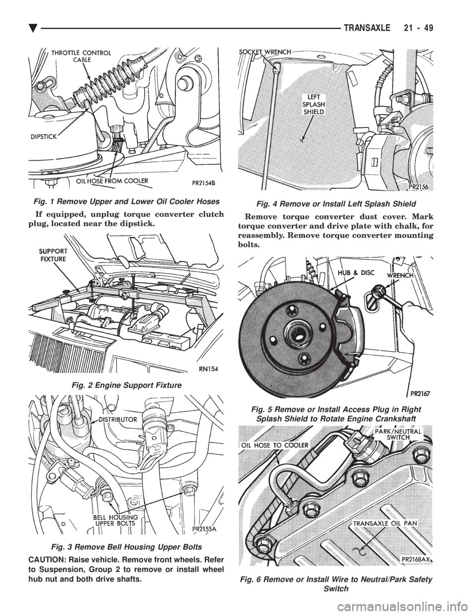
If equipped, unplug torque converter clutch
plug, located near the dipstick.
CAUTION: Raise vehicle. Remove front wheels. Refer
to Suspension, Group 2 to remove or install wheel
hub nut and both drive shafts. Remove torque converter dust cover. Mark
torque converter and drive plate with chalk, for
reassembly. Remove torque converter mounting
bolts.
Fig. 1 Remove Upper and Lower Oil Cooler Hoses
Fig. 2 Engine Support Fixture
Fig. 3 Remove Bell Housing Upper Bolts
Fig. 4 Remove or Install Left Splash Shield
Fig. 5 Remove or Install Access Plug in Right Splash Shield to Rotate Engine Crankshaft
Fig. 6 Remove or Install Wire to Neutral/Park Safety Switch
Ä TRANSAXLE 21 - 49
Page 2059 of 2438
CAUTION: If the vehicle is equipped with two oil
coolers (one in the radiator tank, one in front of the
radiator) they must be flushed separately. Do not
attempt to flush both coolers at one time. (1) Disconnect the cooler lines at the transmission.
(2) Using a hand suction gun filled with mineral
spirits, reverse flush the cooler. Force mineral spirits
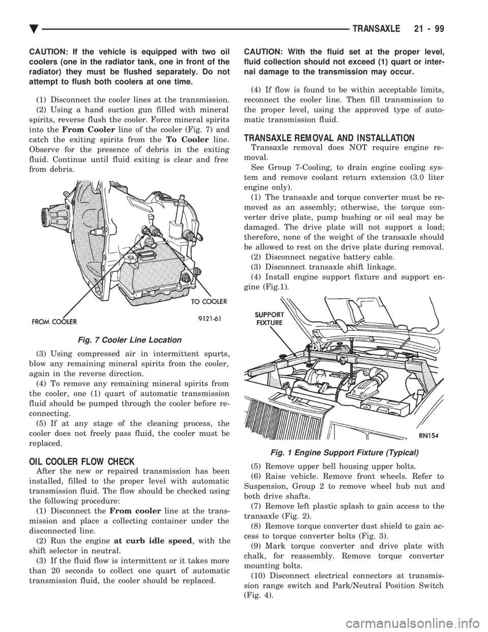
into the From Cooler line of the cooler (Fig. 7) and
catch the exiting spirits from the To Coolerline.
Observe for the presence of debris in the exiting
fluid. Continue until fluid exiting is clear and free
from debris.
(3) Using compressed air in intermittent spurts,
blow any remaining mineral spirits from the cooler,
again in the reverse direction. (4) To remove any remaining mineral spirits from
the cooler, one (1) quart of automatic transmission
fluid should be pumped through the cooler before re-
connecting. (5) If at any stage of the cleaning process, the
cooler does not freely pass fluid, the cooler must be
replaced.
OIL COOLER FLOW CHECK
After the new or repaired transmission has been
installed, filled to the proper level with automatic
transmission fluid. The flow should be checked using
the following procedure: (1) Disconnect the From coolerline at the trans-
mission and place a collecting container under the
disconnected line. (2) Run the engine at curb idle speed , with the
shift selector in neutral. (3) If the fluid flow is intermittent or it takes more
than 20 seconds to collect one quart of automatic
transmission fluid, the cooler should be replaced. CAUTION: With the fluid set at the proper level,
fluid collection should not exceed (1) quart or inter-
nal damage to the transmission may occur.
(4) If flow is found to be within acceptable limits,
reconnect the cooler line. Then fill transmission to
the proper level, using the approved type of auto-
matic transmission fluid.
TRANSAXLE REMOVAL AND INSTALLATION
Transaxle removal does NOT require engine re-
moval. See Group 7-Cooling, to drain engine cooling sys-
tem and remove coolant return extension (3.0 liter
engine only). (1) The transaxle and torque converter must be re-
moved as an assembly; otherwise, the torque con-
verter drive plate, pump bushing or oil seal may be
damaged. The drive plate will not support a load;
therefore, none of the weight of the transaxle should
be allowed to rest on the drive plate during removal. (2) Disconnect negative battery cable.
(3) Disconnect transaxle shift linkage.
(4) Install engine support fixture and support en-
gine (Fig.1).
(5) Remove upper bell housing upper bolts.
(6) Raise vehicle. Remove front wheels. Refer to
Suspension, Group 2 to remove wheel hub nut and
both drive shafts. (7) Remove left plastic splash to gain access to the
transaxle (Fig. 2). (8) Remove torque converter dust shield to gain ac-
cess to torque converter bolts (Fig. 3). (9) Mark torque converter and drive plate with
chalk, for reassembly. Remove torque converter
mounting bolts. (10) Disconnect electrical connectors at transmis-
sion range switch and Park/Neutral Position Switch
(Fig. 4).
Fig. 7 Cooler Line Location
Fig. 1 Engine Support Fixture (Typical)
Ä TRANSAXLE 21 - 99
Page 2169 of 2438
(2) Remove push-in fasteners holding hood latch
cover to radiator closure panel and separate cover
from vehicle. (3) Disconnect hood release cable casing and cable
end from hood latch assembly. Refer to Hood Latch
Removal procedure in this section. (4) Remove hood latch release cable handle attach-
ing bolts from under left lower edge of instrument
panel. (5) Disengage release cable rubber grommet from
engine compartment dash panel behind instrument
panel. (6) Rout cable assembly through engine compart-
ment around battery, under fender lip, under relay
bank, and under wiring harnesses, toward dash
panel. Push cable through access hole in dash panel
under the brake master cylinder, into passenger com-
partment.
HOOD LATCH RELEASE CABLE INSTALLATION
Reverse the preceding operation.
COWL COVER
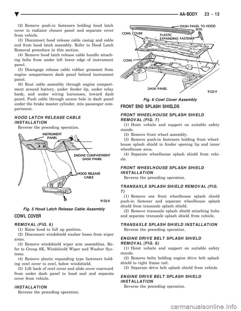
REMOVAL (FIG. 6)
(1) Raise hood to full up position.
(2) Disconnect windshield washer hoses from wiper
arms. (3) Remove windshield wiper arm assemblies. Re-
fer to Group 8K, Windshield Wiper and Washer Sys-
tems. (4) Remove plastic expanding type fasteners hold-
ing cowl cover to cowl, below windshield. (5) Lift back of cowl cover and slide cover rearward
from under dash panel to hood seal and separate
cover from vehicle.
INSTALLATION
Reverse the preceding operation.
FRONT END SPLASH SHIELDS
FRONT WHEELHOUSE SPLASH SHIELD REMOVAL (FIG. 7)
(1) Hoist vehicle and support on suitable safety
stands. (2) Remove front wheel assembly.
(3) Remove push-in fasteners holding front wheel-
house splash shield to fender opening lip and inner
wheelhouse area. (4) Separate wheelhouse splash shield from vehi-
cle.
FRONT WHEELHOUSE SPLASH SHIELD INSTALLATION
Reverse the preceding operation.
TRANSAXLE SPLASH SHIELD REMOVAL (FIG.7)
(1) Remove one front wheelhouse splash shield
push-in fastener and separate wheelhouse splash
shield from transaxle splash shield. (2) Remove transaxle splash shield attaching bolts
and separate transaxle splash shield from vehicle.
TRANSAXLE SPLASH SHIELD INSTALLATION
Reverse the preceding operation.
ENGINE DRIVE BELT SPLASH SHIELD REMOVAL (FIG. 8)
(1) Hoist vehicle and support on suitable safety
stands. (2) Remove bolts holding engine drive belt splash
shield to right frame rail. (3) Separate drive belt splash shield from vehicle.
ENGINE DRIVE BELT SPLASH SHIELDINSTALLATION
Reverse the preceding operation.
Fig. 5 Hood Latch Release Cable Assembly
Fig. 6 Cowl Cover Assembly
Ä AA-BODY 23 - 13
Page 2170 of 2438
FRONT FENDER
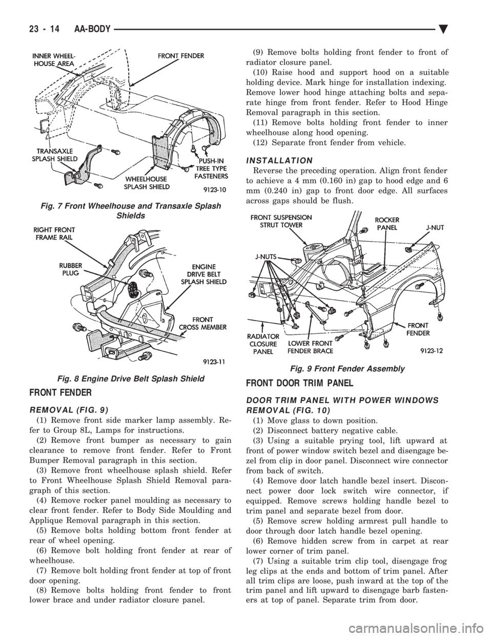
REMOVAL (FIG. 9)
(1) Remove front side marker lamp assembly. Re-
fer to Group 8L, Lamps for instructions. (2) Remove front bumper as necessary to gain
clearance to remove front fender. Refer to Front
Bumper Removal paragraph in this section. (3) Remove front wheelhouse splash shield. Refer
to Front Wheelhouse Splash Shield Removal para-
graph of this section. (4) Remove rocker panel moulding as necessary to
clear front fender. Refer to Body Side Moulding and
Applique Removal paragraph in this section. (5) Remove bolts holding bottom front fender at
rear of wheel opening. (6) Remove bolt holding front fender at rear of
wheelhouse. (7) Remove bolt holding front fender at top of front
door opening. (8) Remove bolts holding front fender to front
lower brace and under radiator closure panel. (9) Remove bolts holding front fender to front of
radiator closure panel. (10) Raise hood and support hood on a suitable
holding device. Mark hinge for installation indexing.
Remove lower hood hinge attaching bolts and sepa-
rate hinge from front fender. Refer to Hood Hinge
Removal paragraph in this section. (11) Remove bolts holding front fender to inner
wheelhouse along hood opening. (12) Separate front fender from vehicle.
INSTALLATION
Reverse the preceding operation. Align front fender
to achiev ea4mm (0.160 in) gap to hood edge and 6
mm (0.240 in) gap to front door edge. All surfaces
across gaps should be flush.
FRONT DOOR TRIM PANEL
DOOR TRIM PANEL WITH POWER WINDOWS REMOVAL (FIG. 10)
(1) Move glass to down position.
(2) Disconnect battery negative cable.
(3) Using a suitable prying tool, lift upward at
front of power window switch bezel and disengage be-
zel from clip in door panel. Disconnect wire connector
from back of switch. (4) Remove door latch handle bezel insert. Discon-
nect power door lock switch wire connector, if
equipped. Remove screws holding handle bezel to
trim panel and separate bezel from door. (5) Remove screw holding armrest pull handle to
door through door latch handle bezel opening. (6) Remove hidden screw from in carpet at rear
lower corner of trim panel. (7) Using a suitable trim clip tool, disengage frog
leg clips at the ends and bottom of trim panel. After
all trim clips are loose, push inward at the top of the
trim panel and lift upward to disengage barb fasten-
ers at top of panel. Separate trim from door.
Fig. 7 Front Wheelhouse and Transaxle Splash Shields
Fig. 8 Engine Drive Belt Splash Shield
Fig. 9 Front Fender Assembly
23 - 14 AA-BODY Ä
Page 2172 of 2438
(6) Separate door from vehicle.
FRONT DOOR INSTALLATION
Reverse the preceding operation. The door should
not require re-alignment. If door does need align-
ment, refer to Front Door Hinge Installation para-
graph in this section.
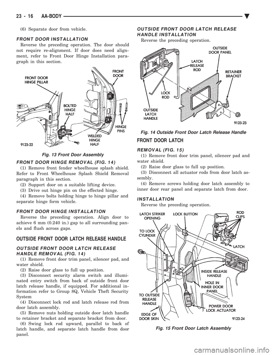
FRONT DOOR HINGE REMOVAL (FIG. 14)
(1) Remove front fender wheelhouse splash shield.
Refer to Front Wheelhouse Splash Shield Removal
paragraph in this section. (2) Support door on a suitable lifting device.
(3) Drive out hinge pin on the effected hinge.
(4) Remove bolts holding hinge to hinge pillar and
separate hinge form vehicle.
FRONT DOOR HINGE INSTALLATION
Reverse the preceding operation. Align door to
achieve 6 mm (0.240 in.) gap to all surrounding pan-
els and flush across gaps.
OUTSIDE FRONT DOOR LATCH RELEASE HANDLE
OUTSIDE FRONT DOOR LATCH RELEASE HANDLE REMOVAL (FIG. 14)
(1) Remove front door trim panel, silencer pad, and
water shield. (2) Raise door glass to full up position.
(3) Disconnect security alarm switch and illumi-
nated entry switch from back of outside front door
latch release handle, if equipped. For additional in-
formation refer to Group 8Q, Vehicle Theft Security
System (4) Disconnect lock rod and latch release rod from
door latch assembly. (5) Remove nuts holding outside door latch handle
to retainer bracket and separate bracket from door. (6) Swing lock rod upward, parallel to back of
latch handle, and separate latch handle from door
panel.
OUTSIDE FRONT DOOR LATCH RELEASE
HANDLE INSTALLATION
Reverse the preceding operation.
FRONT DOOR LATCH
REMOVAL (FIG. 15)
(1) Remove front door trim panel, silencer pad and
water shield. (2) Raise door glass to full up position.
(3) Disconnect all actuator rods from door latch as-
sembly. (4) Remove screws holding door latch assembly to
inner door rear panel and separate latch from door.
INSTALLATION
Reverse the preceding operation.
Fig. 13 Front Door Assembly
Fig. 14 Outside Front Door Latch Release Handle
Fig. 15 Front Door Latch Assembly
23 - 16 AA-BODY Ä
Page 2184 of 2438
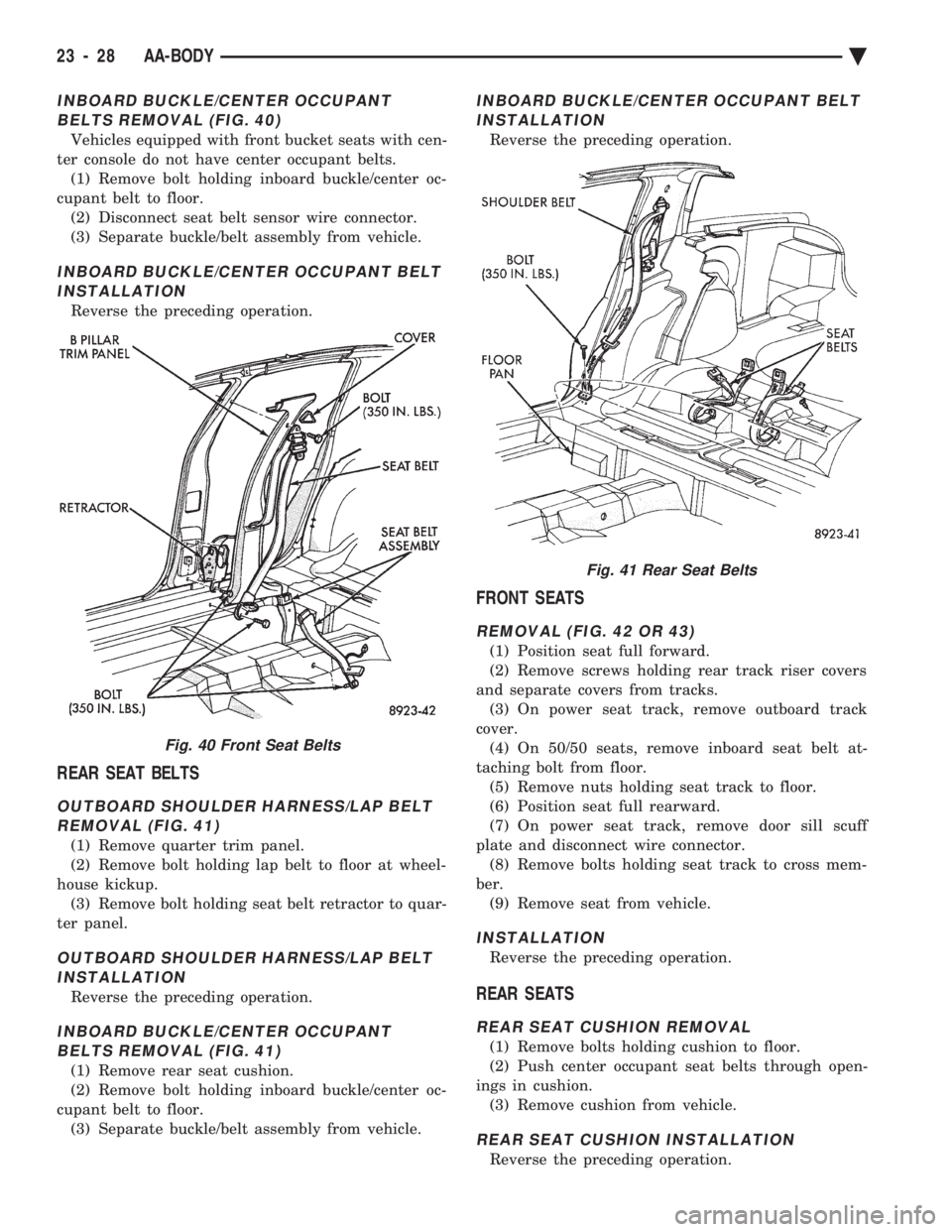
INBOARD BUCKLE/CENTER OCCUPANT BELTS REMOVAL (FIG. 40)
Vehicles equipped with front bucket seats with cen-
ter console do not have center occupant belts. (1) Remove bolt holding inboard buckle/center oc-
cupant belt to floor. (2) Disconnect seat belt sensor wire connector.
(3) Separate buckle/belt assembly from vehicle.
INBOARD BUCKLE/CENTER OCCUPANT BELT INSTALLATION
Reverse the preceding operation.
REAR SEAT BELTS
OUTBOARD SHOULDER HARNESS/LAP BELTREMOVAL (FIG. 41)
(1) Remove quarter trim panel.
(2) Remove bolt holding lap belt to floor at wheel-
house kickup. (3) Remove bolt holding seat belt retractor to quar-
ter panel.
OUTBOARD SHOULDER HARNESS/LAP BELT INSTALLATION
Reverse the preceding operation.
INBOARD BUCKLE/CENTER OCCUPANTBELTS REMOVAL (FIG. 41)
(1) Remove rear seat cushion.
(2) Remove bolt holding inboard buckle/center oc-
cupant belt to floor. (3) Separate buckle/belt assembly from vehicle.
INBOARD BUCKLE/CENTER OCCUPANT BELTINSTALLATION
Reverse the preceding operation.
FRONT SEATS
REMOVAL (FIG. 42 OR 43)
(1) Position seat full forward.
(2) Remove screws holding rear track riser covers
and separate covers from tracks. (3) On power seat track, remove outboard track
cover. (4) On 50/50 seats, remove inboard seat belt at-
taching bolt from floor. (5) Remove nuts holding seat track to floor.
(6) Position seat full rearward.
(7) On power seat track, remove door sill scuff
plate and disconnect wire connector. (8) Remove bolts holding seat track to cross mem-
ber. (9) Remove seat from vehicle.
INSTALLATION
Reverse the preceding operation.
REAR SEATS
REAR SEAT CUSHION REMOVAL
(1) Remove bolts holding cushion to floor.
(2) Push center occupant seat belts through open-
ings in cushion. (3) Remove cushion from vehicle.
REAR SEAT CUSHION INSTALLATION
Reverse the preceding operation.
Fig. 40 Front Seat Belts
Fig. 41 Rear Seat Belts
23 - 28 AA-BODY Ä
Page 2196 of 2438
panel. Push cable through access hole in dash panel
under the brake master cylinder, into passenger com-
partment.
INSTALLATION
Reverse the preceding operation.
FRONT END SPLASH SHIELDS
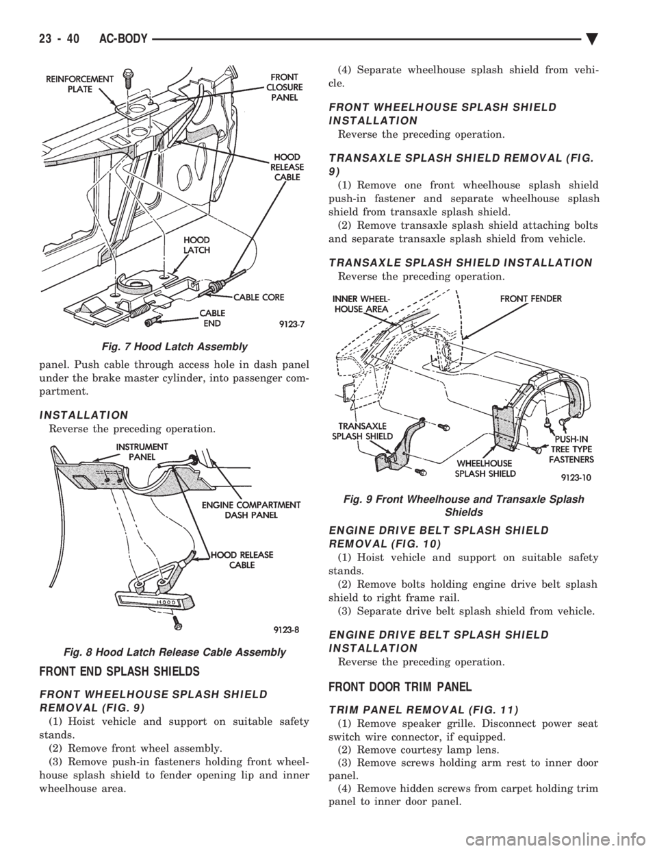
FRONT WHEELHOUSE SPLASH SHIELD REMOVAL (FIG. 9)
(1) Hoist vehicle and support on suitable safety
stands. (2) Remove front wheel assembly.
(3) Remove push-in fasteners holding front wheel-
house splash shield to fender opening lip and inner
wheelhouse area. (4) Separate wheelhouse splash shield from vehi-
cle.
FRONT WHEELHOUSE SPLASH SHIELD INSTALLATION
Reverse the preceding operation.
TRANSAXLE SPLASH SHIELD REMOVAL (FIG.9)
(1) Remove one front wheelhouse splash shield
push-in fastener and separate wheelhouse splash
shield from transaxle splash shield. (2) Remove transaxle splash shield attaching bolts
and separate transaxle splash shield from vehicle.
TRANSAXLE SPLASH SHIELD INSTALLATION
Reverse the preceding operation.
ENGINE DRIVE BELT SPLASH SHIELD REMOVAL (FIG. 10)
(1) Hoist vehicle and support on suitable safety
stands. (2) Remove bolts holding engine drive belt splash
shield to right frame rail. (3) Separate drive belt splash shield from vehicle.
ENGINE DRIVE BELT SPLASH SHIELDINSTALLATION
Reverse the preceding operation.
FRONT DOOR TRIM PANEL
TRIM PANEL REMOVAL (FIG. 11)
(1) Remove speaker grille. Disconnect power seat
switch wire connector, if equipped. (2) Remove courtesy lamp lens.
(3) Remove screws holding arm rest to inner door
panel. (4) Remove hidden screws from carpet holding trim
panel to inner door panel.
Fig. 7 Hood Latch Assembly
Fig. 8 Hood Latch Release Cable Assembly
Fig. 9 Front Wheelhouse and Transaxle Splash Shields
23 - 40 AC-BODY Ä
Page 2205 of 2438
REAR SEATS
REAR SEAT CUSHION REMOVAL
(1) Remove bolts holding cushion to floor.
(2) Disconnect center occupant seat belts from
cushion. (3) Remove cushion from vehicle.
REAR SEAT CUSHION INSTALLATION
Reverse the preceding operation.
REAR SEAT BACK REMOVAL
(1) Remove rear seat cushion assembly.
(2) Remove bolts holding seat back to rear floor
kick-up. (3) Lift seat back upward to disengage upper hooks
from shelf support panel. (4) Separate seat back from vehicle.
REAR SEAT BACK INSTALLATION
Reverse the preceding operation.
BODY MOULDINGS
STICK-ON BODY SIDE MOULDING REMOVALAND INSTALLATION
(1) Warm the effected stick-on moulding and body
metal to approximately 38ÉC (100ÉF) using a suitable
heat lamp or heat gun. (2) Pull stick-on moulding from painted surface.
(3) Remove adhesive tape residue from painted
surface of vehicle. (4) If moulding is to be reused, Remove tape resi-
due from moulding. Clean back of moulding with Mo-
par t, Super Kleen solvent or equivalent. Wipe
moulding dry with lint free cloth. Apply new body
side moulding (two sided adhesive) tape to back of
moulding. (5) Clean body surface with Super Kleen solvent or
equivalent. Wipe surface dry with lint free cloth. (6) Apply a length of masking tape on the body,
parallel to the top edge of the moulding to use as a
guide, if necessary. (7) Remove protective cover from tape on back of
moulding. Apply moulding to body below the mask-
ing tape guide. (8) Remove masking tape guide and heat body and
moulding, see step one. Firmly press moulding to
body surface to assure adhesion.
FRONT WHEEL OPENING MOULDING REMOVAL
(1) Remove screws holding wheel opening mould-
ing to front fender. (2) Separate moulding from fender.
FRONT WHEEL OPENING MOULDINGINSTALLATION
(1) Position moulding in wheel opening and start
top center screw of wheel opening moulding. (2) Install screws around wheel opening.
REAR WHEEL OPENING MOULDING REMOVAL
(1) Remove screws holding wheel opening mould-
ing to quarter panel. (2) Separate wheel opening moulding from quarter
panel.
REAR WHEEL OPENING MOULDING INSTALLATION
(1) Position moulding in wheel opening and start
top center screw of wheel opening moulding. (2) Install screws around wheel opening.
VINYL ROOF BONNET
REMOVAL (FIG. 27)
(1) Remove quarter panel trim covers.
(2) Remove head lining.
(3) Remove nuts holding transverse roof moulding
to roof panel and separate moulding from vehicle. (4) Remove nuts holding vinyl top bonnet to roof.
(5) Remove rear deck filler panel.
(6) Remove screws holding rear window opening
lower valance to body. (7) Disengage hook and loop fasteners holding vi-
nyl top bonnet to quarter panel. (8) Pull vinyl top bonnet away from top panel to
separate bonnet from anti-flutter sealer holding bon-
net to roof.
INSTALLATION
(1) Clean anti-flutter sealer from roof surface and
inside of vinyl roof bonnet. (2) Apply a 20 mm (0.75 in.) bead of anti-flutter
sealer across the roof panel at the mid point between
the front of the bonnet and rear of roof. (3) Apply a 20 mm (0.75 in.) by 150 mm (6 in.)
bead of anti-flutter sealer down each roof side panel
at mid point between the door opening and rear of
roof. (4) Place the bonnet into position on the roof panel
and align to proper fit. (5) Reverse the removal operation.
REAR DECK FILLER PANEL
REMOVAL (FIG. 28)
(1) Raise truck lid to full up position.
(2) Remove screws holding rear deck filler panel to
body in the front trunk opening gutter. (3) Close trunk lid, do not latch.
(4) Lift filler panel upward and separate from ve-
hicle.
Ä AC-BODY 23 - 49