1993 CHEVROLET PLYMOUTH ACCLAIM coolant level
[x] Cancel search: coolant levelPage 1863 of 2438
The PCM may receive a closed throttle input from
the throttle position sensor (TPS) when it senses an
abrupt decrease in manifold pressure. This indicates
a hard deceleration. The PCM may reduce injector
firing to once per engine revolution. This helps main-
tain better control of the air-fuel mixture. During a deceleration condition, the PCM grounds
the exhaust gas recirculation (EGR) solenoid. When
the PCM grounds the solenoid, preventing EGR.
WIDE OPEN THROTTLE MODE This is an OPEN LOOP mode. During wide-open-
throttle operation, the following inputs are received
by the PCM:
² engine coolant temperature
² crankshaft position (distributor pick-up)
² manifold absolute pressure
² engine speed (distributor pick-up)
² throttle position
When the PCM senses wide open throttle condition
through the throttle position sensor (TPS) it will:
² Provide a ground for the electrical EGR transducer
(EET) solenoid. When the PCM grounds the solenoid,
the EGR system stops operating.
² De-energize the air conditioning relay. This dis-
ables the air conditioning system. The exhaust gas oxygen content input is not ac-
cepted by the PCM during wide open throttle opera- tion. The PCM will adjust injector pulse width to
supply a predetermined amount of additional fuel.
IGNITION SWITCH OFF MODE
When the ignition switch is turned to the OFF po-
sition, the following occurs:
² All outputs are turned off.
² No inputs are monitored.
² The PCM shuts down.
THROTTLE BODY
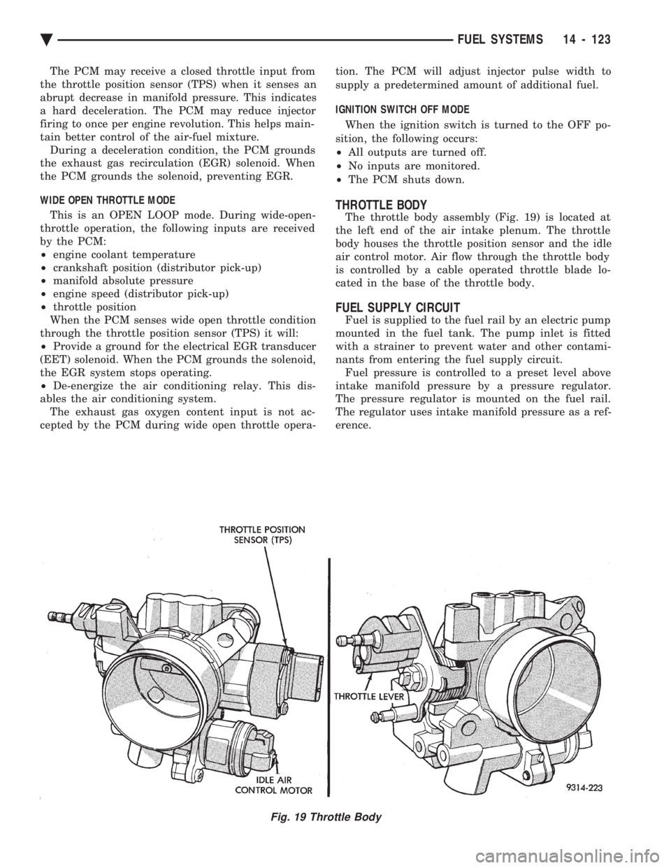
The throttle body assembly (Fig. 19) is located at
the left end of the air intake plenum. The throttle
body houses the throttle position sensor and the idle
air control motor. Air flow through the throttle body
is controlled by a cable operated throttle blade lo-
cated in the base of the throttle body.
FUEL SUPPLY CIRCUIT
Fuel is supplied to the fuel rail by an electric pump
mounted in the fuel tank. The pump inlet is fitted
with a strainer to prevent water and other contami-
nants from entering the fuel supply circuit. Fuel pressure is controlled to a preset level above
intake manifold pressure by a pressure regulator.
The pressure regulator is mounted on the fuel rail.
The regulator uses intake manifold pressure as a ref-
erence.
Fig. 19 Throttle Body
Ä FUEL SYSTEMS 14 - 123
Page 1895 of 2438
WIDE OPEN THROTTLE MODE This is an OPEN LOOP mode. During wide-open-
throttle operation, the following inputs are received
by the PCM:
² battery voltage
² engine coolant temperature
² manifold absolute pressure
² engine speed
² throttle position
When the PCM senses wide open throttle condition
through the throttle position sensor (TPS) it will:
² De-energize the air conditioning relay. This dis-
ables the air conditioning system.
² Provide a ground for the electrical EGR transducer
(EET) solenoid. When the PCM grounds the solenoid,
the EGR system stops operating. The exhaust gas oxygen content input is not ac-
cepted by the PCM during wide open throttle opera-
tion. The PCM will adjust injector pulse width to
supply a predetermined amount of additional fuel.
IGNITION SWITCH OFF MODE When the ignition switch is turned to the OFF po-
sition, the following occurs:
² All outputs are turned off.
² No inputs are monitored.
² The PCM shuts down.
THROTTLE BODY
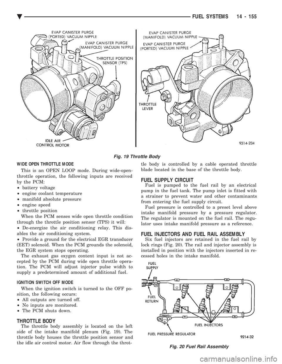
The throttle body assembly is located on the left
side of the intake manifold plenum (Fig. 19). The
throttle body houses the throttle position sensor and
the idle air control motor. Air flow through the throt- tle body is controlled by a cable operated throttle
blade located in the base of the throttle body.
FUEL SUPPLY CIRCUIT
Fuel is pumped to the fuel rail by an electrical
pump in the fuel tank. The pump inlet is fitted with
a strainer to prevent water and other contaminants
from entering the fuel supply circuit. Fuel pressure is controlled to a preset level above
intake manifold pressure by a pressure regulator.
The regulator is mounted on the fuel rail. The regu-
lator uses intake manifold pressure as a reference.
FUEL INJECTORS AND FUEL RAIL ASSEMBLY
Six fuel injectors are retained in the fuel rail by
lock rings (Fig. 20). The rail and injector assembly is
installed in position with the injectors inserted in re-
cessed holes in the intake manifold.
Fig. 19 Throttle Body
Fig. 20 Fuel Rail Assembly
Ä FUEL SYSTEMS 14 - 155
Page 2059 of 2438
CAUTION: If the vehicle is equipped with two oil
coolers (one in the radiator tank, one in front of the
radiator) they must be flushed separately. Do not
attempt to flush both coolers at one time. (1) Disconnect the cooler lines at the transmission.
(2) Using a hand suction gun filled with mineral
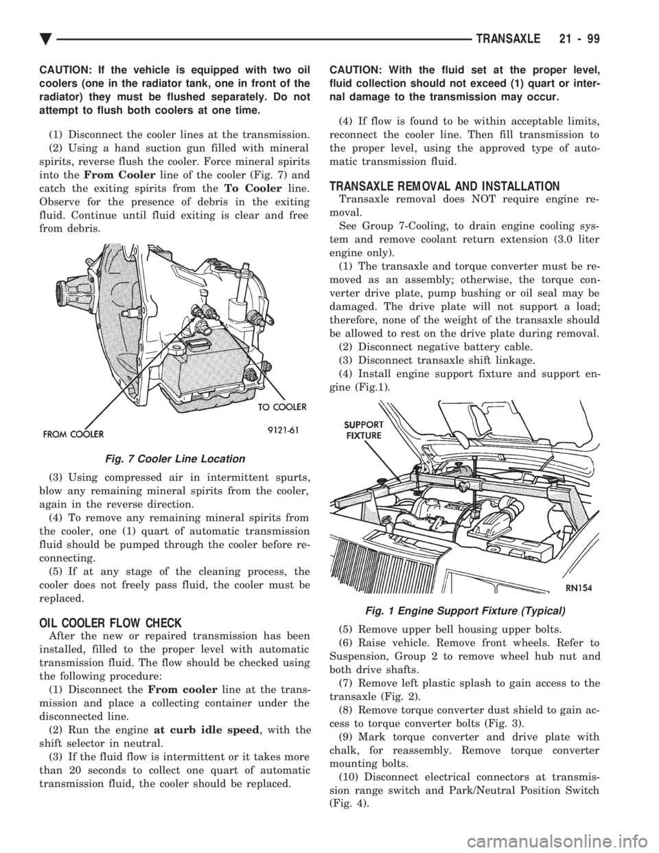
spirits, reverse flush the cooler. Force mineral spirits
into the From Cooler line of the cooler (Fig. 7) and
catch the exiting spirits from the To Coolerline.
Observe for the presence of debris in the exiting
fluid. Continue until fluid exiting is clear and free
from debris.
(3) Using compressed air in intermittent spurts,
blow any remaining mineral spirits from the cooler,
again in the reverse direction. (4) To remove any remaining mineral spirits from
the cooler, one (1) quart of automatic transmission
fluid should be pumped through the cooler before re-
connecting. (5) If at any stage of the cleaning process, the
cooler does not freely pass fluid, the cooler must be
replaced.
OIL COOLER FLOW CHECK
After the new or repaired transmission has been
installed, filled to the proper level with automatic
transmission fluid. The flow should be checked using
the following procedure: (1) Disconnect the From coolerline at the trans-
mission and place a collecting container under the
disconnected line. (2) Run the engine at curb idle speed , with the
shift selector in neutral. (3) If the fluid flow is intermittent or it takes more
than 20 seconds to collect one quart of automatic
transmission fluid, the cooler should be replaced. CAUTION: With the fluid set at the proper level,
fluid collection should not exceed (1) quart or inter-
nal damage to the transmission may occur.
(4) If flow is found to be within acceptable limits,
reconnect the cooler line. Then fill transmission to
the proper level, using the approved type of auto-
matic transmission fluid.
TRANSAXLE REMOVAL AND INSTALLATION
Transaxle removal does NOT require engine re-
moval. See Group 7-Cooling, to drain engine cooling sys-
tem and remove coolant return extension (3.0 liter
engine only). (1) The transaxle and torque converter must be re-
moved as an assembly; otherwise, the torque con-
verter drive plate, pump bushing or oil seal may be
damaged. The drive plate will not support a load;
therefore, none of the weight of the transaxle should
be allowed to rest on the drive plate during removal. (2) Disconnect negative battery cable.
(3) Disconnect transaxle shift linkage.
(4) Install engine support fixture and support en-
gine (Fig.1).
(5) Remove upper bell housing upper bolts.
(6) Raise vehicle. Remove front wheels. Refer to
Suspension, Group 2 to remove wheel hub nut and
both drive shafts. (7) Remove left plastic splash to gain access to the
transaxle (Fig. 2). (8) Remove torque converter dust shield to gain ac-
cess to torque converter bolts (Fig. 3). (9) Mark torque converter and drive plate with
chalk, for reassembly. Remove torque converter
mounting bolts. (10) Disconnect electrical connectors at transmis-
sion range switch and Park/Neutral Position Switch
(Fig. 4).
Fig. 7 Cooler Line Location
Fig. 1 Engine Support Fixture (Typical)
Ä TRANSAXLE 21 - 99
Page 2310 of 2438
HEATER AND A/C PERFORMANCE TESTS
HEATER OUTPUT TEST
PRE-DIAGNOSTIC PREPARATIONS
Review Safety Precautions and Warnings before
performing the following procedures. Check the radiator coolant level, drive belt tension,
and engine vacuum line connections. Also check ra-
diator air flow and radiator fan operation. Start en-
gine and allow to warm up to normal operating
temperature.
WARNING: DO NOT REMOVE RADIATOR CAP
WHEN ENGINE IS HOT, PERSONAL INJURY CAN
RESULT.
If vehicle has been run recently, wait 15 minutes
before removing cap. Place a rag over the cap and
turn it to the first safety stop. Allow pressure to es-
cape through the overflow tube. When the system
stabilizes, remove the cap completely.
MAXIMUM HEATER OUTPUT: TEST AND ACTION
Engine coolant is provided to the heater system by
two 16 mm (5/8 inch inside diameter) heater hoses.
With engine idling at normal running temperature,
set the control to maximum heat, floor, and high
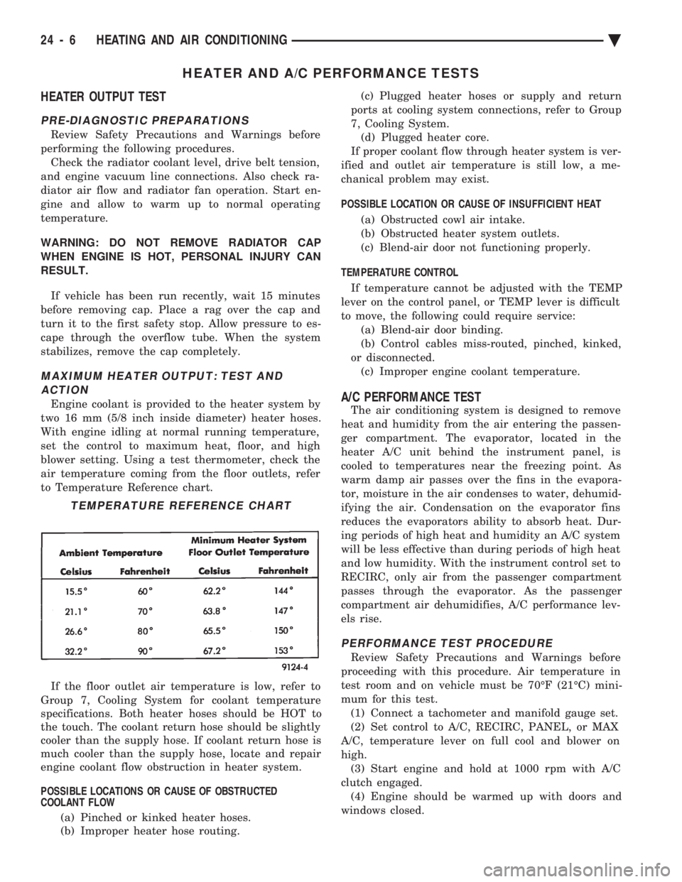
blower setting. Using a test thermometer, check the
air temperature coming from the floor outlets, refer
to Temperature Reference chart.
If the floor outlet air temperature is low, refer to
Group 7, Cooling System for coolant temperature
specifications. Both heater hoses should be HOT to
the touch. The coolant return hose should be slightly
cooler than the supply hose. If coolant return hose is
much cooler than the supply hose, locate and repair
engine coolant flow obstruction in heater system.
POSSIBLE LOCATIONS OR CAUSE OF OBSTRUCTED
COOLANT FLOW
(a) Pinched or kinked heater hoses.
(b) Improper heater hose routing. (c) Plugged heater hoses or supply and return
ports at cooling system connections, refer to Group
7, Cooling System. (d) Plugged heater core.
If proper coolant flow through heater system is ver-
ified and outlet air temperature is still low, a me-
chanical problem may exist.
POSSIBLE LOCATION OR CAUSE OF INSUFFICIENT HEAT
(a) Obstructed cowl air intake.
(b) Obstructed heater system outlets.
(c) Blend-air door not functioning properly.
TEMPERATURE CONTROL If temperature cannot be adjusted with the TEMP
lever on the control panel, or TEMP lever is difficult
to move, the following could require service: (a) Blend-air door binding.
(b) Control cables miss-routed, pinched, kinked,
or disconnected. (c) Improper engine coolant temperature.A/C PERFORMANCE TEST
The air conditioning system is designed to remove
heat and humidity from the air entering the passen-
ger compartment. The evaporator, located in the
heater A/C unit behind the instrument panel, is
cooled to temperatures near the freezing point. As
warm damp air passes over the fins in the evapora-
tor, moisture in the air condenses to water, dehumid-
ifying the air. Condensation on the evaporator fins
reduces the evaporators ability to absorb heat. Dur-
ing periods of high heat and humidity an A/C system
will be less effective than during periods of high heat
and low humidity. With the instrument control set to
RECIRC, only air from the passenger compartment
passes through the evaporator. As the passenger
compartment air dehumidifies, A/C performance lev-
els rise.
PERFORMANCE TEST PROCEDURE
Review Safety Precautions and Warnings before
proceeding with this procedure. Air temperature in
test room and on vehicle must be 70ÉF (21ÉC) mini-
mum for this test. (1) Connect a tachometer and manifold gauge set.
(2) Set control to A/C, RECIRC, PANEL, or MAX
A/C, temperature lever on full cool and blower on
high. (3) Start engine and hold at 1000 rpm with A/C
clutch engaged. (4) Engine should be warmed up with doors and
windows closed.
TEMPERATURE REFERENCE CHART
24 - 6 HEATING AND AIR CONDITIONING Ä
Page 2376 of 2438
NONÐCOMPUTER AIDED DIAGNOSTIC TESTS
Determine whether the operator complaint is due
to a system failure or improper operation of the ATC
system. The system will to go into a maximum heat
or cooling mode if the operator changes the tempera-
ture setting four or more degrees. Check the following:
² Coolant level
² Refrigerant charge
² Drive belt tension
² Radiator air flow
² Radiator fan operation
² Air suction of In-car Temperature Sensor/Aspirator
To check air suction of the Aspirator, place a small
piece of tissue paper over the Aspirator opening on
the instrument panel. This opening is located to the
right of the steering column. The tissue paper should
cling to the opening if system is functioning properly. Bring the engine to normal operating temperature
and proceed with Computer Aided Diagnostic Proce-
dures. Always test the entire system after each re-
pair has been performed.
COMPUTER AIDED DIAGNOSTIC TESTS
The ATC control has a computer capable of trou-
bleshooting the entire ATC system in approximately
60 seconds. The engine must be running and at nor-
mal operating temperature during the test to provide
hot coolant for the heater. During the ATC Diagnostic Test, the computer will
calibrate the Mode and Blend Door actuators.
CAUTION: Do not remove the actuators from the
heater-A/C unit assembly with power applied. Re-
moval should only be done with the Ignition OFF.
The actuators have no mechanical stops to limit the
travel. If the actuator rotates and is not connected
to the unit assembly, it will become un-calibrated.
The Diagnostic Test is capable of checking all elec-
trical signals between the ATC Control Module, ac-
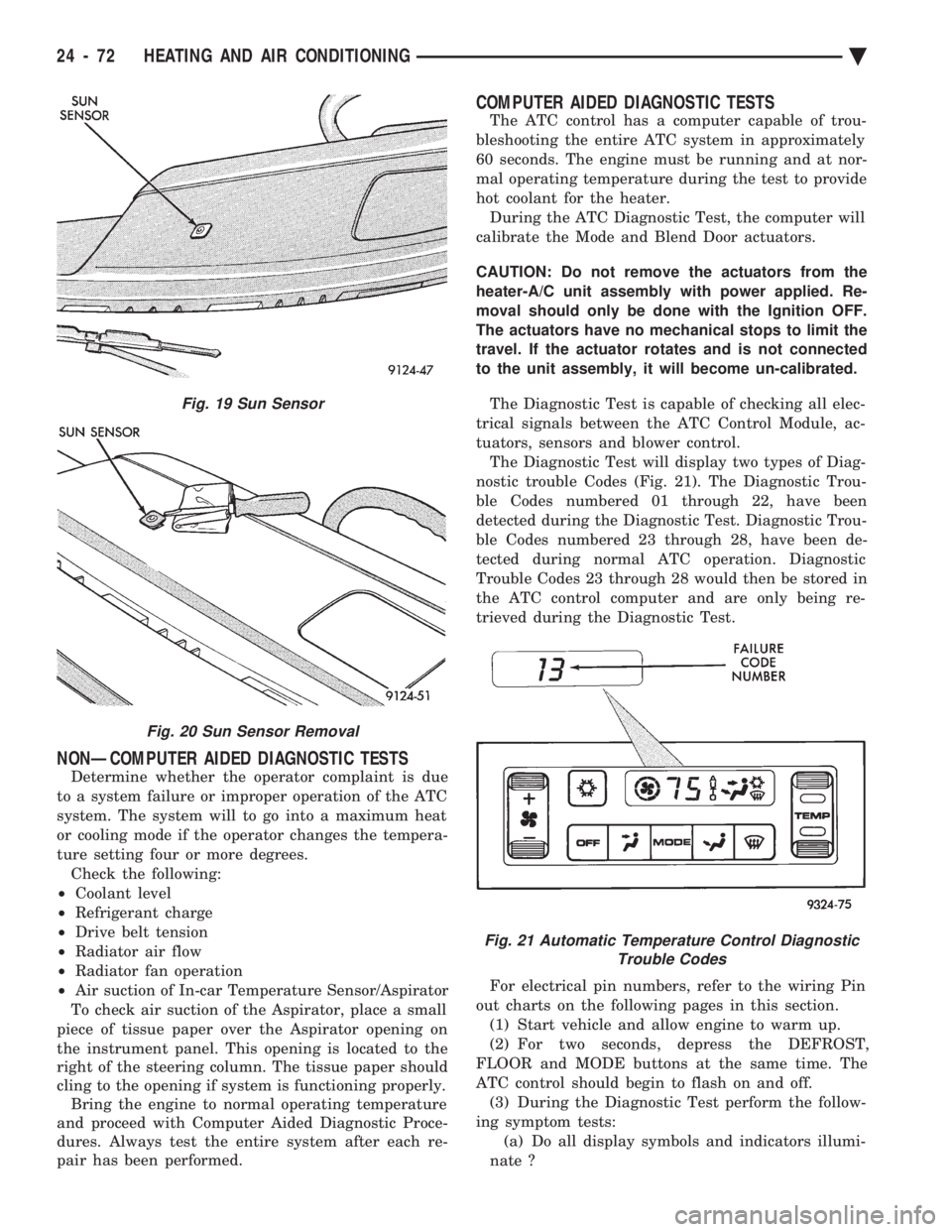
tuators, sensors and blower control. The Diagnostic Test will display two types of Diag-
nostic trouble Codes (Fig. 21). The Diagnostic Trou-
ble Codes numbered 01 through 22, have been
detected during the Diagnostic Test. Diagnostic Trou-
ble Codes numbered 23 through 28, have been de-
tected during normal ATC operation. Diagnostic
Trouble Codes 23 through 28 would then be stored in
the ATC control computer and are only being re-
trieved during the Diagnostic Test.
For electrical pin numbers, refer to the wiring Pin
out charts on the following pages in this section. (1) Start vehicle and allow engine to warm up.
(2) For two seconds, depress the DEFROST,
FLOOR and MODE buttons at the same time. The
ATC control should begin to flash on and off. (3) During the Diagnostic Test perform the follow-
ing symptom tests: (a) Do all display symbols and indicators illumi-
nate ?
Fig. 19 Sun Sensor
Fig. 20 Sun Sensor Removal
Fig. 21 Automatic Temperature Control Diagnostic Trouble Codes
24 - 72 HEATING AND AIR CONDITIONING Ä