1993 CHEVROLET PLYMOUTH ACCLAIM spark plugs
[x] Cancel search: spark plugsPage 470 of 2438

SCAVENGER DEPOSITS Fuel scavenger deposits may be either white or yel-
low (Fig. 12). They may appear to be harmful, but
are a normal condition caused by chemical additives
in certain fuels. These additives are designed to
change the chemical nature of deposits and decrease
spark plug misfire tendencies. Accumulation on the
ground electrode and shell area may be heavy but
the deposits are easily removed. Spark plugs with
scavenger deposits can be considered normal in con-
dition and be cleaned using standard procedures.
CHIPPED ELECTRODE INSULATOR A chipped electrode insulator usually results from
bending the center electrode while adjusting the
spark plug electrode gap. Under certain conditions,
severe detonation also can separate the insulator
from the center electrode (Fig. 13). Spark plugs with
chipped electrode insulators must be replaced.
PREIGNITION DAMAGE
Excessive combustion chamber temperature can
cause preignition damage. First, the center electrode
dissolves and the ground electrode dissolves some- what later (Fig. 14). Insulators appear relatively de-
posit free. Determine if the spark plug has the
correct heat range rating for the engine, if ignition
timing is over advanced or if other operating condi-
tions are causing engine overheating. The heat range
rating refers to the operating temperature of a par-
ticular type spark plug. Spark plugs are designed to
operate within specific temperature ranges depend-
ing upon the thickness and length of the center elec-
trode and porcelain insulator.
SPARK PLUG OVERHEATING
Overheating is indicated by a white or gray center
electrode insulator that also appears blistered (Fig.
15). The increase in electrode gap will be consider-
ably in excess of 0.001 in per 1000 miles of operation.
This suggests that a plug with a cooler heat range
rating should be used. Over advanced ignition tim-
ing, detonation and cooling system malfunctions also
can cause spark plug overheating.
CAMSHAFT POSITION SENSOR
The camshaft position sensor provides fuel injection
synchronization and cylinder identification informa-
Fig. 12 Scavenger Deposits
Fig. 13 Chipped Electrode Insulator
Fig. 14 Preignition Damage
Fig. 15 Spark Plug Overheating
8D - 28 IGNITION SYSTEMS Ä
Page 473 of 2438

tion timing from the crankshaft position sensor. Once
crankshaft position has been determined, the PCM
begins energizing the injectors in sequence.On Turbo III engines, the crankshaft position sensor
is located in the transaxle housing, below the throttle
body (Fig. 26). On 3.3L and 3.8L engines, the crank-
shaft position sensor is located in the transaxle hous-
ing (Fig. 27). The bottom of the sensor is positioned next to the
drive plate. The distance between the bottom of
sensor and the drive plate is critical to the op-
eration of the system. When servicing the crank-
shaft sensor, refer to the 3.3L Ignition
SystemÐService Procedures section in this
Group.IGNITION COIL
WARNING: THE DIRECT IGNITION SYSTEM GENER-
ATES APPROXIMATELY 40,000 VOLTS. PERSONAL
INJURY COULD RESULT FROM CONTACT WITH
THIS SYSTEM.
The 3.3L and 3.8L coil assembly consists of 3 coils
molded together (Fig. 28). The assembly is mounted
on the intake manifold. The 2.2L Turbo III coil as-
sembly consists of 2 coils molded together (Fig. 29).
The assembly is mounted at the front of the engine.
For all engines, the number of each coil appears on
the front of the coil pack.
High tension leads route to each cylinder from the
coil. The coil fires two spark plugs every power
stroke. One plug is the cylinder under compression,
the other cylinder fires on the exhaust stroke. The
PCM determines which of the coils to charge and fire
at the correct time. On 3.3L and 3.8L engines, coil one fires cylinders 1
and 4, coil two fires cylinders 2 and 5, coil three fires
cylinders three and six.
Fig. 28 Coil PackÐ2.2L Turbo III Engine
Fig. 29 Coil PackÐ3.3L and 3.8L Engines
Fig. 26 Crankshaft Position Sensor LocationÐTurbo III Engines
Fig. 27 Crankshaft Position Sensor LocationÐ3.3Land 3.8L Engines
Ä IGNITION SYSTEMS 8D - 31
Page 483 of 2438

(2) With engine running, move test probe along
entire length of all cables (approximately 0 to 1/8
inch gap). If punctures or cracks are present there
will be a noticeable spark jump from the faulty area
to the probe. Cracked, leaking or faulty cables should
be replaced. Use the following procedure when removing the
high tension cable from the spark plug. First, remove
the cable from the retaining bracket. Then grasp the
terminal as close as possible to the spark plug. Ro-
tate the cover (boot) slightly and pull straight back.
Do not use pliers and do not pull the cable at an
angle. Doing so will damage the insulation, cable
terminal or the spark plug insulator. Wipe spark
plug insulator clean before reinstalling cable
and cover. Resistance cables are identified by the words Elec-
tronic Suppression .
Use an ohmmeter to check cables for opens, loose
terminals or high resistance. (a) Remove cable from spark plug.
(b) Remove cable from the coil tower.
(c) Connect the ohmmeter between spark plug
end terminal and the coil end terminal. Resistance
should be within tolerance shown in the cable re-
sistance chart. If resistance is not within tolerance,
replace cable assembly. Test all spark plug cables
in same manner.
SPARK PLUG SERVICE
When replacing the spark plug cables, route the ca-
bles correctly and secure them in the appropriate re-
tainers. Incorrectly routed cables can cause the radio
to reproduce ignition noise. It can also cause cross ig-
nition of the spark plugs or short circuit the cables to
ground.
SPARK PLUG REMOVAL
Always remove cables by grasping at boot, rotating
the boot 1/2 turn, and pulling straight back in a
steady motion. (1) Prior to removing the spark plug spray com-
pressed air around the spark plug hole and the area
around the spark plug. (2) Remove the spark plug using a quality socket
with a rubber or foam insert. (3) Inspect the spark plug condition. Refer to
Spark Plug Condition in this section.
SPARK PLUG GAP ADJUSTMENT
Check the spark plug gap with a gap gauge. If the
gap is not correct, adjust it by bending the ground
electrode (Fig. 6).
SPARK PLUG INSTALLATION
(1) To avoid cross threading, start the spark plug
into the cylinder head by hand. (2) Tighten spark plugs to 28 N Im (20 ft. lbs.)
torque. (3) Install spark plug cables over spark plugs.
IDLE RPM TEST
WARNING: BE SURE TO APPLY PARKING BRAKE
AND/OR BLOCK WHEELS BEFORE PERFORMING
ANY ENGINE RUNNING TESTS.
Engine idle set rpmshould be tested and recorded
as it is when the vehicle is first brought into shop
for testing. This will assist in diagnosing complaints
of engine stalling, creeping and hard shifting on ve-
hicles equipped with automatic transaxle. Refer to the
Throttle Body Minimum Airflow procedures in Group
14.
IGNITION TIMING PROCEDURE
Ignition timing cannot be changed or set on Turbo
III, 3.3L or 3.8L engines. For diagnostic information,
refer to the DRBII scan tool and the appropriate
Powertrain Diagnostics Procedures manual.
CABLE RESISTANCE CHART
Fig. 6 Setting Spark Plug GapÐTypical
Ä IGNITION SYSTEMS 8D - 41
Page 491 of 2438
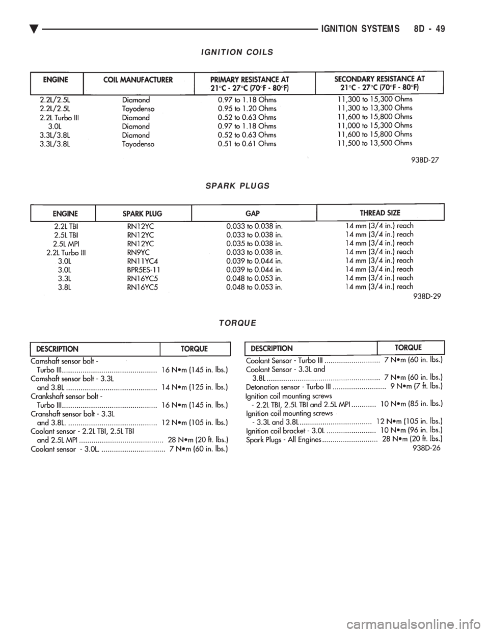
IGNITION COILS
SPARK PLUGS
TORQUE
Ä IGNITION SYSTEMS 8D - 49
Page 1568 of 2438
The MOPAR Silicone Rubber Adhesive Sealant
gasket material or equivalent should be applied in a
continuous bead approximately 3mm (0.120 inch) in
diameter. All mounting holes must be circled. For
corner sealing, a 3.17 or 6.35 mm (1/8 or 1/4 inch.)
drop is placed in the center of the gasket contact
area. Uncured sealant may be removed with a shop
towels. Components should be torqued in place while
the sealant is still wet to the touch (within 10 min-
utes). The usage of a locating dowel is recommended
during assembly to prevent smearing of material off
location.
CRANKSHAFT SPROCKET BOLT ACCESS PLUG
An Access plug is located in the right inner fender
shield. Remove the plug and insert proper size
socket, extension and rachet, when crankshaft rota-
tion is necessary.
ENGINE PERFORMANCE
If a loss of performance is noticed, ignition timing
should be checked. If ignition timing is retarded by
9, 18 or 27É indicating 1, 2 or 3 (timing belt or chain)
teeth may have skipped, then, camshaft and acces-
sory shaft timing with the crankshaft should be
checked. Refer to Engine Timing Sprockets and Oil
Seals of the Engine Section. To provide best vehicle performance and lowest ve-
hicle emissions, it is most important that the tune-up
be done accurately. Use the specifications listed on
the Vehicle Emission Control Information label
found in the engine compartment. (1) Test cranking amperage draw. See Starting
Motor Cranking Amperage Draw Electrical Section
of this manual. (2) Tighten the intake manifold bolts to specifica-
tions. (3) Perform cylinder compression test.(a) Check engine oil level and add oil if neces-
sary. (b) Drive the vehicle until engine reaches normal
operating temperature. (c) Select a route free from traffic and other
forms of congestion, observe all traffic laws, and ac-
celerate through the gears several times briskly.
CAUTION: Do not overspeed the engine. The higher
engine speed may help clean out valve seat deposits
which can prevent accurate compression readings.
(d) Remove all spark plugs from engine. As
spark plugs are being removed, check electrodes for
abnormal firing indicators fouled, hot, oily, etc.
Record cylinder number of spark plug for future
reference. (e) Disconnect coil wire from distributor and se-
cure to good ground to prevent a spark from start- ing a fire (Conventional Ignition System). For Direct
Ignition System DIS disconnect the coil connector. (f) Be sure throttle blade is fully open during the
compression check. (g) Insert compression gage adaptor into the #1
spark plug hole in cylinder head. Crank engine until
maximum pressure is reached on gage. Record this
pressure as #1 cylinder pressure. (h) Repeat Step G for all remaining cylinders.
(i) Compression should not be less than (689kPa)
100 psi and not vary more than 25 percent from
cylinder to cylinder. (j) If one or more cylinders have abnormally low
compression pressures, repeat steps 3b through 3h. (k) If the same cylinder or cylinders repeat an
abnormally low reading on the second compression
test, it could indicate the existence of a problem in
the cylinder in question.
The recommended compression pressures are
to be used only as a guide to diagnosing engine
problems. An engine should not be disassembled
to determine the cause of low compression un-
less some malfunction is present. (4) Clean or replace spark plugs as necessary and
adjust gap as specified in Electrical Group 8. Tighten to
specifications. (5) Test resistance of spark plug cables. Refer to
Ignition System Secondary Circuit Inspection Electri-
cal Section Group 8. (6) Inspect the primary wire. Test coil output volt-
age, primary and secondary resistance. Replace parts
as necessary. Refer to Ignition System and make nec-
essary adjustment. (7) Ignition timing should be set to specifications.
(See Specification Label in engine compartment). (8) Test fuel pump for pressure and vacuum. Refer to
Fuel System Group 14, Specifications. (9) The air filter elements should be replaced as
specified in Lubrication and Maintenance, Group 0. (10) Inspect crankcase ventilation system as out
lined in Lubrication and Maintenance, Group 0. For
emission controls see Emission Controls Group 25 for
service procedures. (11) Inspect and adjust accessory belt drives refer-
ring to Accessory Belt Drive in Cooling System, Group
7 for proper adjustments. (12) Road test vehicle as a final test.
HONING CYLINDER BORES
Before honing, stuff plenty of clean shop towels
under the bores, over the crankshaft to keep abrasive
materials from entering crankcase area. (1) Used carefully, the cylinder bore resizing hone
C-823 equipped with 220 grit stones, is the best tool for
this job. In addition to deglazing, it will reduce taper
and out-of-round as well as removing light
9 - 2 ENGINE Ä
Page 1571 of 2438
CAUTION: Be sure that the tapped holes maintain
the original centerline.
Heli-Coil tools and inserts are readily available
from automotive parts jobbers.
HYDROSTATIC LOCKED ENGINE
When an engine is suspected to be hydrostaticly
locked, regardless of what caused the problem, these
steps should be used.
CAUTION: Do Not Use Starter Motor To Rotate En-
gine, severe damage may occur.
(1) Inspect air cleaner, induction system and in-
take manifold to insure system is dry and clear of
foreign material. (2) Remove negative battery cable.
(3) Place a shop towel around the spark plugs
when removing them from the engine. This will
catch any fluid that may possibly be in the cylinder
under pressure. (4) With all spark plugs removed, rotate engine
crankshaft using a breaker bar and socket. (5) Identify the fluid in the cylinder(s) (i.e., cool-
ant, fuel, oil or other). (6) Make sure all fluid has been removed from the
cylinders. Inspect engine for damage (i.e., Connecting
Rods, Pistons, Valves etc.) (7) Repair engine or components as necessary to
prevent this problem from occurring again.
CAUTION: Squirt approximately 1 teaspoon of oil
into cylinders, rotate engine to lubricate the cylin-
der walls to prevent damage on restart.
(8) Install new spark plugs.
(9) Drain engine oil and remove oil filter.
(10) Fill engine with specified amount of approved
oil and install new oil filter. (11) Connect negative battery cable.
(12) Start engine and check for any leaks.
Ä ENGINE 9 - 5
Page 1586 of 2438
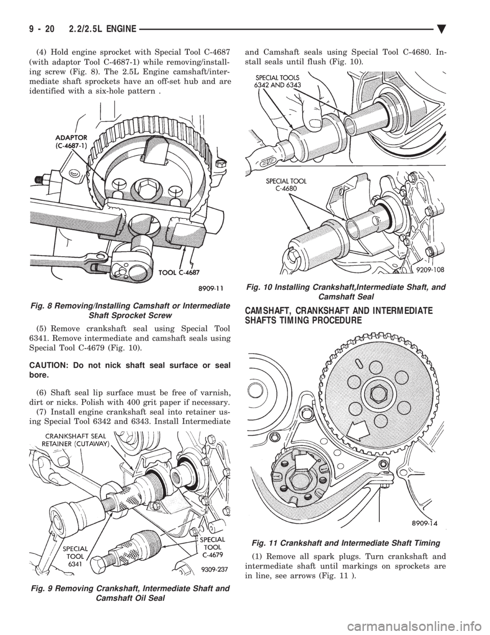
(4) Hold engine sprocket with Special Tool C-4687
(with adaptor Tool C-4687-1) while removing/install-
ing screw (Fig. 8). The 2.5L Engine camshaft/inter-
mediate shaft sprockets have an off-set hub and are
identified with a six-hole pattern .
(5) Remove crankshaft seal using Special Tool
6341. Remove intermediate and camshaft seals using
Special Tool C-4679 (Fig. 10).
CAUTION: Do not nick shaft seal surface or seal
bore.
(6) Shaft seal lip surface must be free of varnish,
dirt or nicks. Polish with 400 grit paper if necessary. (7) Install engine crankshaft seal into retainer us-
ing Special Tool 6342 and 6343. Install Intermediate and Camshaft seals using Special Tool C-4680. In-
stall seals until flush (Fig. 10).
CAMSHAFT, CRANKSHAFT AND INTERMEDIATE
SHAFTS TIMING PROCEDURE
(1) Remove all spark plugs. Turn crankshaft and
intermediate shaft until markings on sprockets are
in line, see arrows (Fig. 11 ).
Fig. 9 Removing Crankshaft, Intermediate Shaft and Camshaft Oil Seal
Fig. 8 Removing/Installing Camshaft or IntermediateShaft Sprocket Screw
Fig. 10 Installing Crankshaft,Intermediate Shaft, and Camshaft Seal
Fig. 11 Crankshaft and Intermediate Shaft Timing
9 - 20 2.2/2.5L ENGINE Ä
Page 1587 of 2438
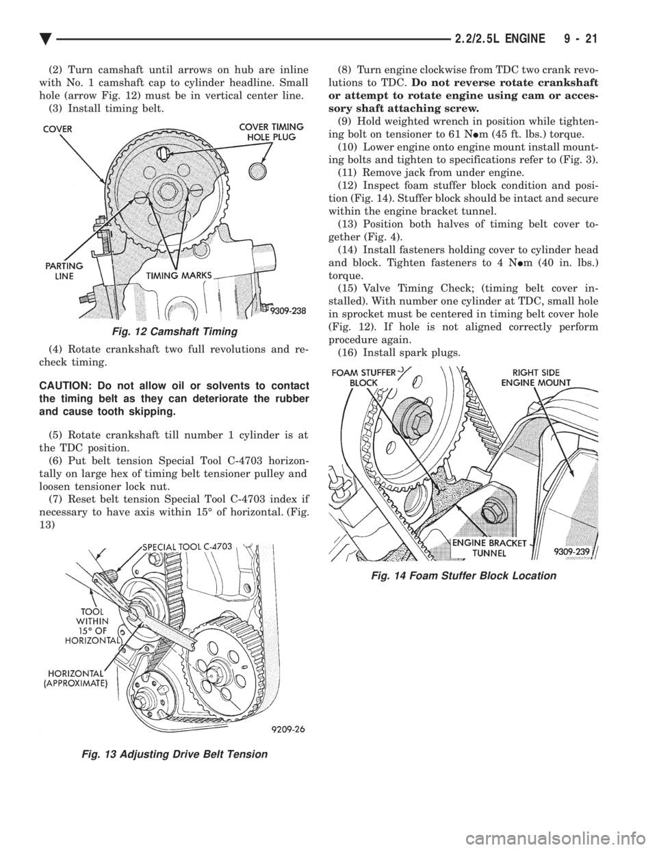
(2) Turn camshaft until arrows on hub are inline
with No. 1 camshaft cap to cylinder headline. Small
hole (arrow Fig. 12) must be in vertical center line. (3) Install timing belt.
(4) Rotate crankshaft two full revolutions and re-
check timing.
CAUTION: Do not allow oil or solvents to contact
the timing belt as they can deteriorate the rubber
and cause tooth skipping.
(5) Rotate crankshaft till number 1 cylinder is at
the TDC position. (6) Put belt tension Special Tool C-4703 horizon-
tally on large hex of timing belt tensioner pulley and
loosen tensioner lock nut. (7) Reset belt tension Special Tool C-4703 index if
necessary to have axis within 15É of horizontal. (Fig.
13) (8) Turn engine clockwise from TDC two crank revo-
lutions to TDC. Do not reverse rotate crankshaft
or attempt to rotate engine using cam or acces-
sory shaft attaching screw. (9) Hold weighted wrench in position while tighten-
ing bolt on tensioner to 61 N Im (45 ft. lbs.) torque.
(10) Lower engine onto engine mount install mount-
ing bolts and tighten to specifications refer to (Fig. 3). (11) Remove jack from under engine.
(12) Inspect foam stuffer block condition and posi-
tion (Fig. 14). Stuffer block should be intact and secure
within the engine bracket tunnel. (13) Position both halves of timing belt cover to-
gether (Fig. 4). (14) Install fasteners holding cover to cylinder head
and block. Tighten fasteners to 4 N Im (40 in. lbs.)
torque. (15) Valve Timing Check; (timing belt cover in-
stalled). With number one cylinder at TDC, small hole
in sprocket must be centered in timing belt cover hole
(Fig. 12). If hole is not aligned correctly perform
procedure again. (16) Install spark plugs.
Fig. 12 Camshaft Timing
Fig. 13 Adjusting Drive Belt Tension
Fig. 14 Foam Stuffer Block Location
Ä 2.2/2.5L ENGINE 9 - 21