1993 CHEVROLET PLYMOUTH ACCLAIM spark plugs
[x] Cancel search: spark plugsPage 1600 of 2438
CAMSHAFT AND CRANKSHAFT TIMING
PROCEDURE
INSTALLATION
(1) Remove air cleaner fresh air duct.
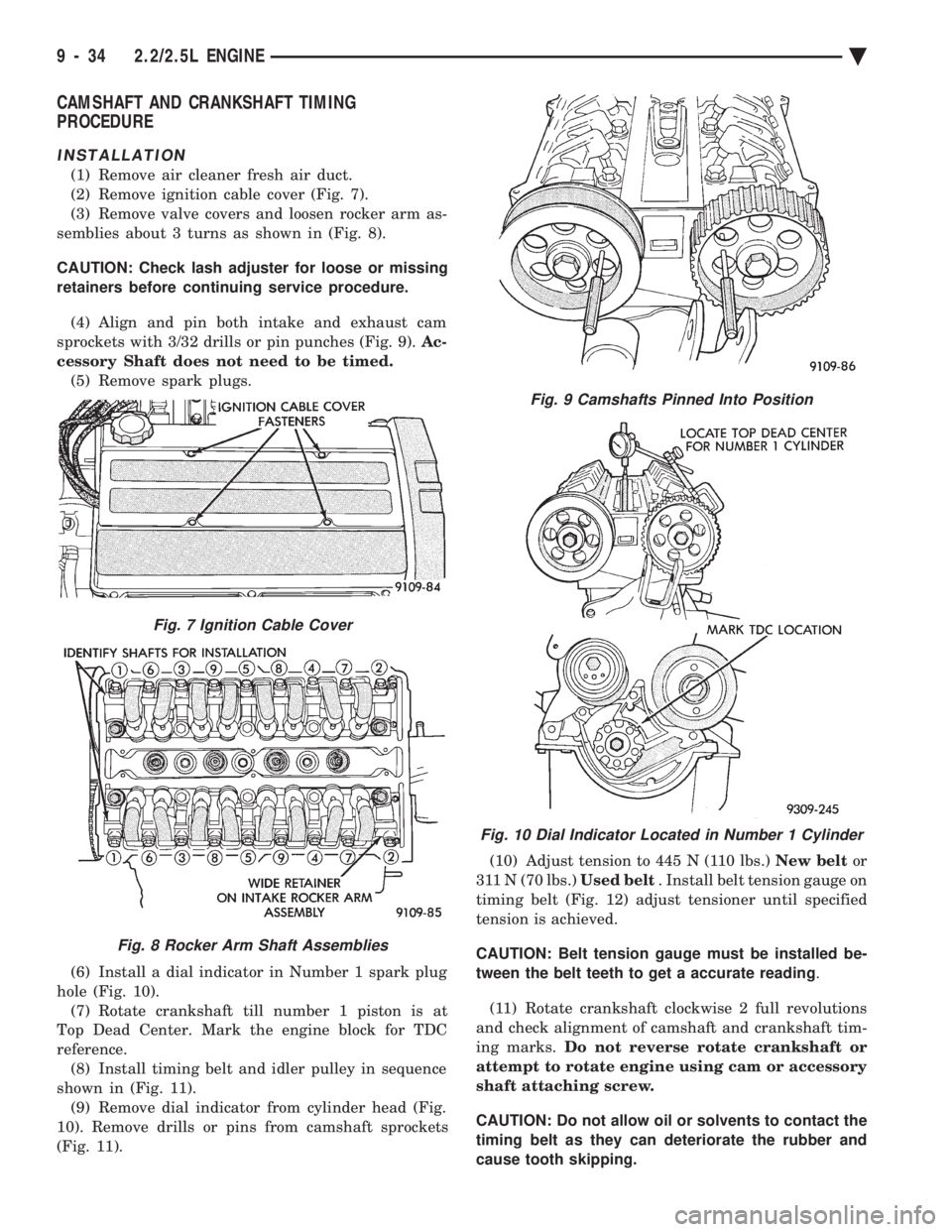
(2) Remove ignition cable cover (Fig. 7).
(3) Remove valve covers and loosen rocker arm as-
semblies about 3 turns as shown in (Fig. 8).
CAUTION: Check lash adjuster for loose or missing
retainers before continuing service procedure.
(4) Align and pin both intake and exhaust cam
sprockets with 3/32 drills or pin punches (Fig. 9). Ac-
cessory Shaft does not need to be timed. (5) Remove spark plugs.
(6) Install a dial indicator in Number 1 spark plug
hole (Fig. 10). (7) Rotate crankshaft till number 1 piston is at
Top Dead Center. Mark the engine block for TDC
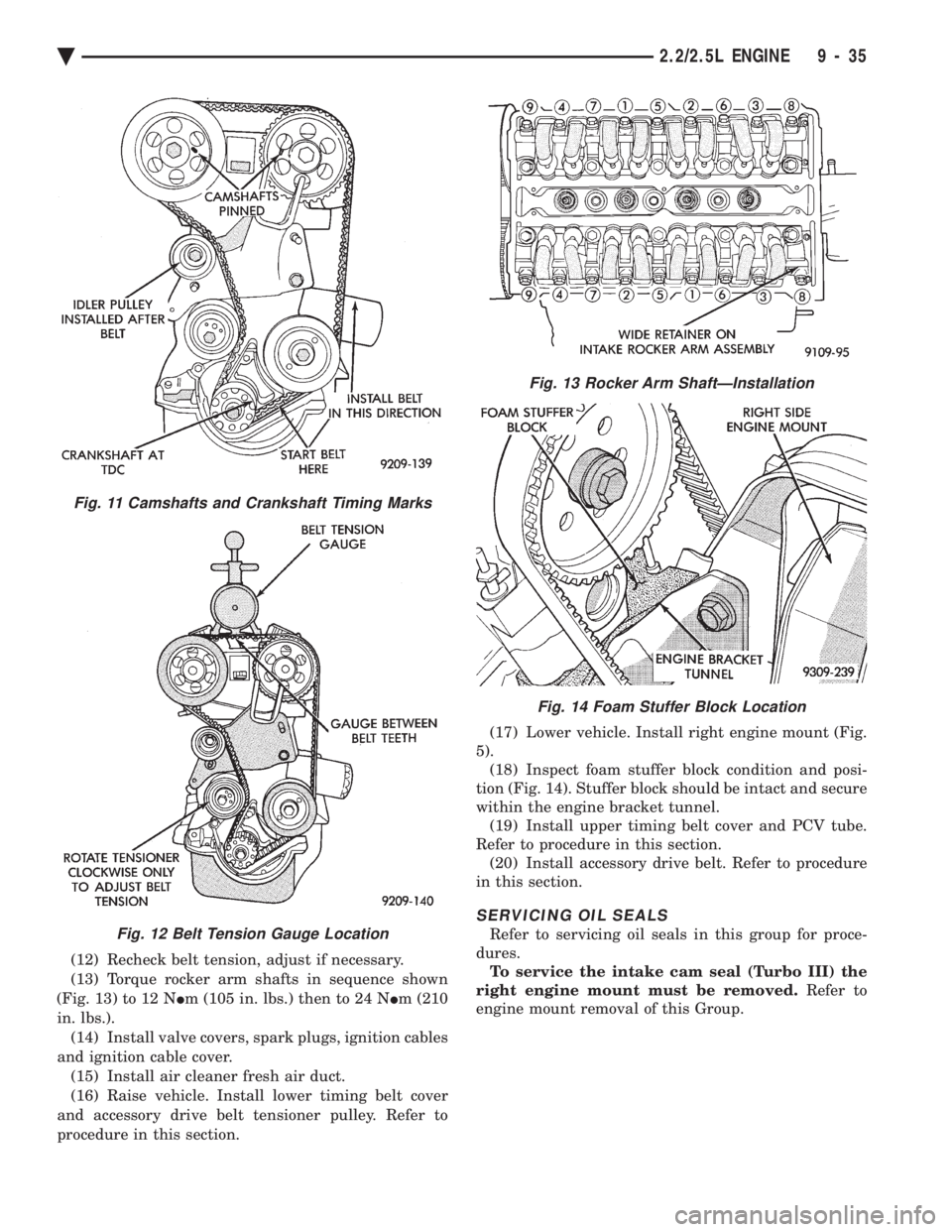
reference. (8) Install timing belt and idler pulley in sequence
shown in (Fig. 11). (9) Remove dial indicator from cylinder head (Fig.
10). Remove drills or pins from camshaft sprockets
(Fig. 11). (10) Adjust tension to 445 N (110 lbs.)
New beltor
311 N (70 lbs.) Used belt. Install belt tension gauge on
timing belt (Fig. 12) adjust tensioner until specified
tension is achieved.
CAUTION: Belt tension gauge must be installed be-
tween the belt teeth to get a accurate reading .
(11) Rotate crankshaft clockwise 2 full revolutions
and check alignment of camshaft and crankshaft tim-
ing marks. Do not reverse rotate crankshaft or
attempt to rotate engine using cam or accessory
shaft attaching screw.
CAUTION: Do not allow oil or solvents to contact the
timing belt as they can deteriorate the rubber and
cause tooth skipping.
Fig. 7 Ignition Cable Cover
Fig. 8 Rocker Arm Shaft Assemblies
Fig. 9 Camshafts Pinned Into Position
Fig. 10 Dial Indicator Located in Number 1 Cylinder
9 - 34 2.2/2.5L ENGINE Ä
Page 1601 of 2438
(12) Recheck belt tension, adjust if necessary.
(13) Torque rocker arm shafts in sequence shown
(Fig. 13) to 12 N Im (105 in. lbs.) then to 24 N Im (210
in. lbs.). (14) Install valve covers, spark plugs, ignition cables
and ignition cable cover. (15) Install air cleaner fresh air duct.
(16) Raise vehicle. Install lower timing belt cover
and accessory drive belt tensioner pulley. Refer to
procedure in this section. (17) Lower vehicle. Install right engine mount (Fig.
5). (18) Inspect foam stuffer block condition and posi-
tion (Fig. 14). Stuffer block should be intact and secure
within the engine bracket tunnel. (19) Install upper timing belt cover and PCV tube.
Refer to procedure in this section. (20) Install accessory drive belt. Refer to procedure
in this section.
SERVICING OIL SEALS
Refer to servicing oil seals in this group for proce-
dures. To service the intake cam seal (Turbo III) the
right engine mount must be removed. Refer to
engine mount removal of this Group.
Fig. 13 Rocker Arm ShaftÐInstallation
Fig. 14 Foam Stuffer Block Location
Fig. 11 Camshafts and Crankshaft Timing Marks
Fig. 12 Belt Tension Gauge Location
Ä 2.2/2.5L ENGINE 9 - 35
Page 1668 of 2438
(15) Install hood.
(16) Connect battery.
(17) Start engine and run until operating temper-
ature is reached. (18) Adjust transmission or linkage if necessary.
ROCKER ARMS AND SHAFT ASSEMBLY
REMOVAL
(1) Remove upper intake manifold assembly. Refer
to Intake and Exhaust Manifolds, Group 11. (2) Disconnect spark plug wires by pulling on the
boot straight out in line with plug. (3) Disconnect closed ventilation system and evap-
oration control system from cylinder head cover. (4) Remove cylinder head cover and gasket.
(5) Remove four rocker shaft bolts and retainers.
(6) Remove rocker arms and shaft assembly.
(7) If rocker arm assemblies are disassembled for
cleaning or replacement. Assemble rocker arms in
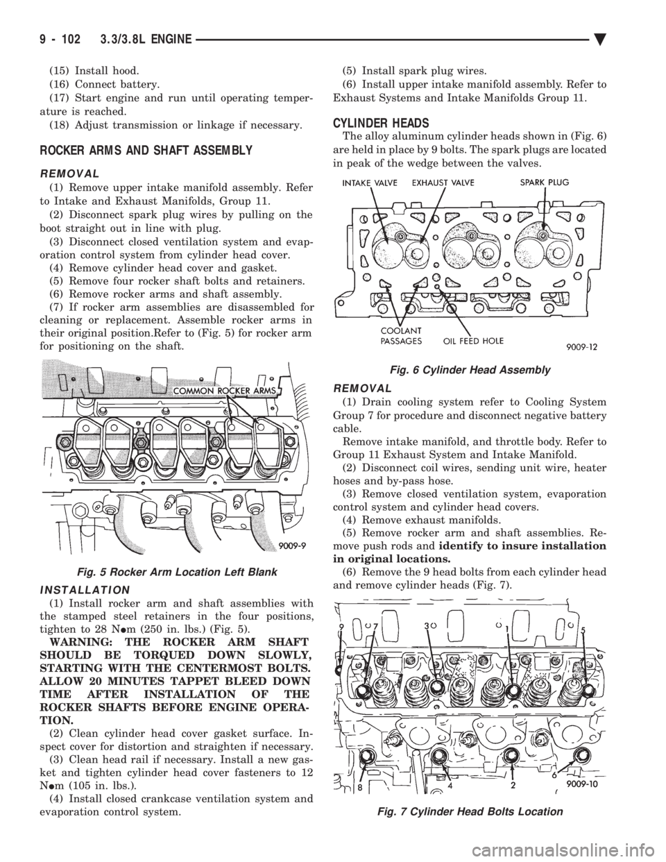
their original position.Refer to (Fig. 5) for rocker arm
for positioning on the shaft.
INSTALLATION
(1) Install rocker arm and shaft assemblies with
the stamped steel retainers in the four positions,
tighten to 28 N Im (250 in. lbs.) (Fig. 5).
WARNING: THE ROCKER ARM SHAFT
SHOULD BE TORQUED DOWN SLOWLY,
STARTING WITH THE CENTERMOST BOLTS.
ALLOW 20 MINUTES TAPPET BLEED DOWN
TIME AFTER INSTALLATION OF THE
ROCKER SHAFTS BEFORE ENGINE OPERA-
TION. (2) Clean cylinder head cover gasket surface. In-
spect cover for distortion and straighten if necessary. (3) Clean head rail if necessary. Install a new gas-
ket and tighten cylinder head cover fasteners to 12
N Im (105 in. lbs.).
(4) Install closed crankcase ventilation system and
evaporation control system. (5) Install spark plug wires.
(6) Install upper intake manifold assembly. Refer to
Exhaust Systems and Intake Manifolds Group 11.
CYLINDER HEADS
The alloy aluminum cylinder heads shown in (Fig. 6)
are held in place by 9 bolts. The spark plugs are located
in peak of the wedge between the valves.
REMOVAL
(1) Drain cooling system refer to Cooling System
Group 7 for procedure and disconnect negative battery
cable. Remove intake manifold, and throttle body. Refer to
Group 11 Exhaust System and Intake Manifold. (2) Disconnect coil wires, sending unit wire, heater
hoses and by-pass hose. (3) Remove closed ventilation system, evaporation
control system and cylinder head covers. (4) Remove exhaust manifolds.
(5) Remove rocker arm and shaft assemblies. Re-
move push rods and identify to insure installation
in original locations. (6) Remove the 9 head bolts from each cylinder head
and remove cylinder heads (Fig. 7).
Fig. 5 Rocker Arm Location Left Blank
Fig. 6 Cylinder Head Assembly
Fig. 7 Cylinder Head Bolts Location
9 - 102 3.3/3.8L ENGINE Ä
Page 1670 of 2438
(8) Place new cylinder head cover gaskets in position
and install cylinder head covers. Tighten to 12 N Im
(105 in. lbs.).
INTAKE MANIFOLD SEALING
The intake manifold gasket is a one-piece stamped
steel gasket with a sealer applied from the manufac-
turer. This gasket has end seals incorporated with it. WARNING: INTAKE MANIFOLD GASKET IS
MADE OF VERY THIN METAL AND MAY CAUSE
PERSONAL INJURY, HANDLE WITH CARE. (1) Clean all surfaces of cylinder block and cylinder
heads. (2) Place a drop ( about 1/4 in. diameter) of Mopar
Silicone Rubber Adhesive Sealant or equivalent, onto
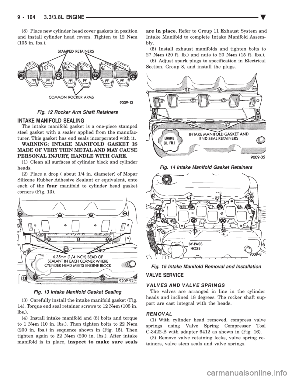
each of the fourmanifold to cylinder head gasket
corners (Fig. 13).
(3) Carefully install the intake manifold gasket (Fig.
14). Torque end seal retainer screws to 12 N Im (105 in.
lbs.). (4) Install intake manifold and (8) bolts and torque
to1N Im (10 in. lbs.). Then tighten bolts to 22 N Im
(200 in. lbs.) in sequence shown in (Fig. 15). Then
tighten again to 22 N Im (200 in. lbs.). After intake
manifold is in place, inspect to make sure seals are in place.
Refer to Group 11 Exhaust System and
Intake Manifold to complete Intake Manifold Assem-
bly. (5) Install exhaust manifolds and tighten bolts to
27 N Im (20 ft. lb.) and nuts to 20 N Im (15 ft. lbs.).
(6) Adjust spark plugs to specification in Electrical
Section, Group 8, and install the plugs.
VALVE SERVICE
VALVES AND VALVE SPRINGS
The valves are arranged in line in the cylinder
heads and inclined 18 degrees. The rocker shaft sup-
port are cast integral with the heads.
REMOVAL
(1) With cylinder head removed, compress valve
springs using Valve Spring Compressor Tool
C-3422-B with adapter 6412 as shown in (Fig. 16). (2) Remove valve retaining locks, valve spring re-
tainers, valve stem seals and valve springs.
Fig. 14 Intake Manifold Gasket Retainers
Fig. 15 Intake Manifold Removal and Installation
Fig. 12 Rocker Arm Shaft Retainers
Fig. 13 Intake Manifold Gasket Sealing
9 - 104 3.3/3.8L ENGINE Ä
Page 1673 of 2438
length of the spring to be tested is 33.34mm (1-5/16
inches). Turn table of Tool C-647 until surface is in line
with the 33.34mm (1-5/16 inch) mark on the threaded
stud and the zero mark on the front. Place spring over
stud on the table and lift compressing lever to set tone
device. Pull on torque wrench until ping is heard. Take
reading on torque wrench at this instant. Multiply this
reading by two. This will give the spring load at test
length. Fractional measurements are indicated on the
table for finer adjustments. Refer to specifications to
obtain specified height and allowable tensions. Discard
the springs that do not meet specifications.
VALVE INSTALLATION
(1) Coat valve stems with clean engine oil and insert
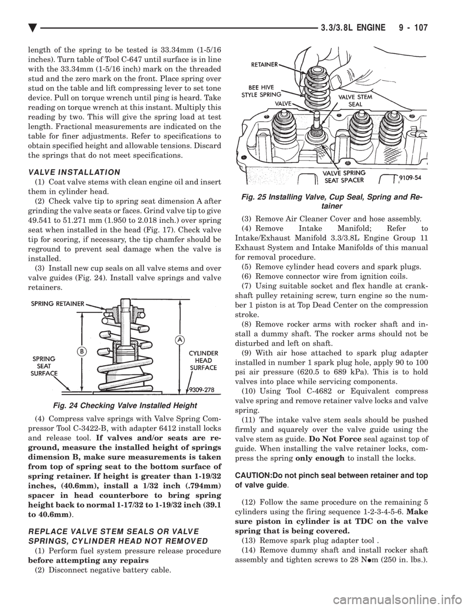
them in cylinder head. (2) Check valve tip to spring seat dimension A after
grinding the valve seats or faces. Grind valve tip to give
49.541 to 51.271 mm (1.950 to 2.018 inch.) over spring
seat when installed in the head (Fig. 17). Check valve
tip for scoring, if necessary, the tip chamfer should be
reground to prevent seal damage when the valve is
installed. (3) Install new cup seals on all valve stems and over
valve guides (Fig. 24). Install valve springs and valve
retainers.
(4) Compress valve springs with Valve Spring Com-
pressor Tool C-3422-B, with adapter 6412 install locks
and release tool. If valves and/or seats are re-
ground, measure the installed height of springs
dimension B, make sure measurements is taken
from top of spring seat to the bottom surface of
spring retainer. If height is greater than 1-19/32
inches, (40.6mm), install a 1/32 inch (.794mm)
spacer in head counterbore to bring spring
height back to normal 1-17/32 to 1-19/32 inch (39.1
to 40.6mm) .
REPLACE VALVE STEM SEALS OR VALVE
SPRINGS, CYLINDER HEAD NOT REMOVED
(1) Perform fuel system pressure release procedure
before attempting any repairs (2) Disconnect negative battery cable. (3) Remove Air Cleaner Cover and hose assembly.
(4) Remove Intake Manifold; Refer to
Intake/Exhaust Manifold 3.3/3.8L Engine Group 11
Exhaust System and Intake Manifolds of this manual
for removal procedure. (5) Remove cylinder head covers and spark plugs.
(6) Remove connector wire from ignition coils.
(7) Using suitable socket and flex handle at crank-
shaft pulley retaining screw, turn engine so the num-
ber 1 piston is at Top Dead Center on the compression
stroke. (8) Remove rocker arms with rocker shaft and in-
stall a dummy shaft. The rocker arms should not be
disturbed and left on shaft. (9) With air hose attached to spark plug adapter
installed in number 1 spark plug hole, apply 90 to 100
psi air pressure (620.5 to 689 kPa). This is to hold
valves into place while servicing components. (10) Using Tool C-4682 or Equivalent compress
valve spring and remove retainer valve locks and valve
spring. (11) The intake valve stem seals should be pushed
firmly and squarely over the valve guide using the
valve stem as guide. Do Not Forceseal against top of
guide. When installing the valve retainer locks, com-
press the spring only enoughto install the locks.
CAUTION:Do not pinch seal between retainer and top
of valve guide .
(12) Follow the same procedure on the remaining 5
cylinders using the firing sequence 1-2-3-4-5-6. Make
sure piston in cylinder is at TDC on the valve
spring that is being covered. (13) Remove spark plug adapter tool .
(14) Remove dummy shaft and install rocker shaft
assembly and tighten screws to 28 N Im (250 in. lbs.).
Fig. 24 Checking Valve Installed Height
Fig. 25 Installing Valve, Cup Seal, Spring and Re-
tainer
Ä 3.3/3.8L ENGINE 9 - 107
Page 1675 of 2438
(2) Clean varnish deposits from inside of tappet
body above plunger cap. (3) Invert tappet body and remove plunger cap,
plunger, flat or ball check valve, check valve spring,
check valve retainer and plunger spring. Check valve
could be flat or ball.
CLEANING AND ASSEMBLY
(1) Clean all tappet parts in a solvent that will re-
move all varnish and carbon. (2) Replace tappets that are unfit for further ser-
vice with new assemblies. (3) If plunger shows signs of scoring or wear, valve
is pitted, or valve seat on end of plunger indicates
any condition that would prevent valve from seating,
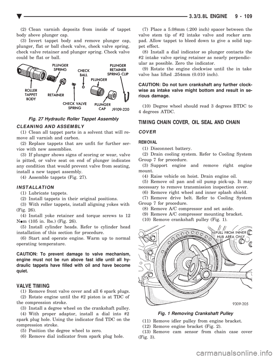
install a new tappet assembly. (4) Assemble tappets (Fig. 27).
INSTALLATION
(1) Lubricate tappets.
(2) Install tappets in their original positions.
(3) With roller tappets, install aligning yokes with
(Fig. 26). (4) Install yoke retainer and torque screws to 12
N Im (105 in. lbs.) (Fig. 26).
(5) Install cylinder heads. Refer to cylinder head
installation of this section for procedure. (6) Start and operate engine. Warm up to normal
operating temperature.
CAUTION: To prevent damage to valve mechanism,
engine must not be run above fast idle until all hy-
draulic tappets have filled with oil and have become
quiet.
VALVE TIMING
(1) Remove front valve cover and all 6 spark plugs.
(2) Rotate engine until the #2 piston is at TDC of
the compression stroke. (3) Install a degree wheel on the crankshaft pulley.
(4) With proper adaptor, install a dial into #2
spark plug hole. Using the indicator find TDC on the
compression stroke. (5) Position the degree wheel to zero.
(6) Remove dial indicator from spark plug hole. (7) Place a 5.08mm (.200 inch) spacer between the
valve stem tip of #2 intake valve and rocker arm
pad. Allow tappet to bleed down to give a solid tap-
pet effect. (8) Install a dial indicator so plunger contacts the
#2 intake valve spring retainer as nearly perpendic-
ular as possible. Zero the indicator. (9) Rotate the engine clockwise until the in take
valve has lifted .254mm (0.010 inch).
CAUTION: Do not turn crankshaft any further clock-
wise as intake valve might bottom and result in se-
rious damage.
(10) Degree wheel should read 3 degrees BTDC to
4 degrees ATDC.
TIMING CHAIN COVER, OIL SEAL AND CHAIN
COVER
REMOVAL
(1) Disconnect battery.
(2) Drain cooling system. Refer to Cooling System
Group 7 for procedure. (3) Support engine and remove right engine
mount. (4) Raise vehicle on hoist. Drain engine oil.
(5) Remove oil pan and oil pump pick-up. It may
necessary to remove transmission inspection cover. (6) Remove right wheel and inner splash shield.
(7) Remove drive belt. Refer to Cooling System
Group 7 for procedure. (8) Remove A/C compressor and set aside.
(9) Remove A/C compressor mounting bracket.
(10) Remove crankshaft pulley (Fig. 1).
(11) Remove idler pulley from engine bracket.
(12) Remove engine bracket (Fig. 2).
(13) Remove cam sensor from chain case cover
(Fig. 3).
Fig. 27 Hydraulic Roller Tappet Assembly
Fig. 1 Removing Crankshaft Pulley
Ä 3.3/3.8L ENGINE 9 - 109
Page 1699 of 2438
CAUTION: Avoid application of rust prevention
compounds or undercoating materials to exhaust
system floor pan heat shields on cars if equipped.
Light overspray near the edges is permitted. Appli-
cation of coating will greatly reduce the efficiency
of the heat shields resulting in excessive floor pan
temperatures and objectionable fumes.
The combustion reaction caused by the catalyst re-
leases additional heat in the exhaust system. Caus-
ing temperature increases in the area of the reactor
under severe operating conditions. Such conditions
can exist when the engine misfires or otherwise does
not operate at peak efficiency. Do notremove spark
plug wires from plugs or by any other means short
out cylinders if exhaust system is equipped with cat-
alytic converter. Failure of the catalytic converter
can occur due to temperature increases caused by un-
burned fuel passing through the converter. The use of the catalysts also involves some non-au-
tomotive problems. Unleaded gasoline must be used
to avoid poisoning the catalyst core. Do not allow en- gine to operate above 1200 RPM in neutral for ex-
tended periods over 5 minutes. This condition may
result in excessive exhaust system/floor pan temper-
atures because of no air movement under the vehicle.
EXHAUST GAS RECIRCULATION (EGR) SYSTEM
To assist in the control of oxides of nitrogen (NOx)
in engine exhaust, some engines are equipped with
an exhaust gas recirculation system. The use of ex-
haust gas to dilute incoming air/fuel mixtures lowers
peak flame temperatures during combustion, thus
limiting the formation of NOx. Exhaust gases are taken from openings in the ex-
haust gas crossover passage in the intake manifold.
REFER TO SECTION 25 EMISSION SYSTEMS
FOR A COMPLETE DESCRIPTION, DIAGNOSIS
AND SERVICE PROCEDURES ON THE EXHAUST
GAS RECIRCULATION SYSTEM AND COMPO-
NENTS.
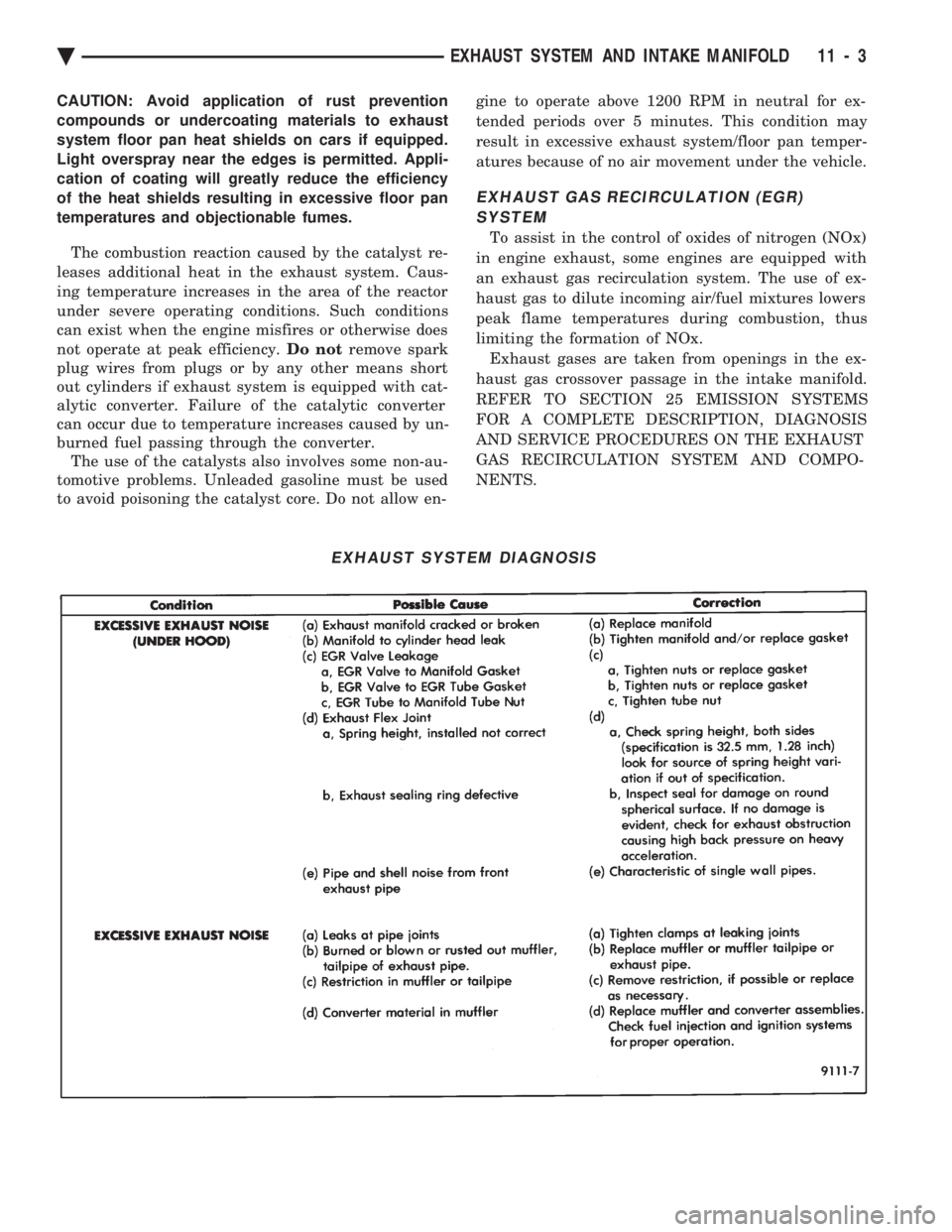
EXHAUST SYSTEM DIAGNOSIS
Ä EXHAUST SYSTEM AND INTAKE MANIFOLD 11 - 3
Page 1782 of 2438
once the system has entered closed loop. Refer to
Modes of Operation in this section for an explanation
of closed loop operation.
NON-MONITORED CIRCUITS
The PCM does not monitor the following circuits,
systems and conditions that could have malfunctions
that result in driveability problems. Diagnostic trou-
ble codes may not be displayed for these conditions.
However, problems with these systems may cause di-
agnostic trouble codes to be displayed for other sys-
tems. For example, a fuel pressure problem will not
register a fault directly, but could cause a rich or
lean condition. This could cause an oxygen sensor
fault to be stored in the PCM. Fuel Pressure - Fuel pressure is controlled by the
fuel pressure regulator. The PCM cannot detect a
clogged fuel pump inlet filter, clogged in-line fuel fil-
ter, or a pinched fuel supply or return line. However,
these could result in a rich or lean condition causing
an oxygen sensor fault. Secondary Ignition Circuit - The PCM cannot
detect an inoperative ignition coil, fouled or worn
spark plugs, ignition cross firing, or open spark plug
cables. Engine Timing - The PCM cannot detect an incor-
rectly indexed timing chain, camshaft sprocket and
crankshaft sprocket. The PCM also cannot detect an
incorrectly indexed distributor. However, these could
result in a rich or lean condition causing an oxygen
sensor fault to be stored in the PCM. Cylinder Compression - The PCM cannot detect
uneven, low, or high engine cylinder compression. Exhaust System
- The PCM cannot detect a
plugged, restricted or leaking exhaust system. Fuel Injector Malfunctions - The PCM cannot
determine if the fuel injector is clogged, the pintle is
sticking or the wrong injector is installed. However,
these could result in a rich or lean condition causing
an oxygen sensor fault to be stored in the PCM. Excessive Oil Consumption - Although the PCM
monitors the exhaust stream oxygen content through
the oxygen sensor when the system is in closed loop,
it cannot determine excessive oil consumption. Throttle Body Air Flow - The PCM cannot detect
a clogged or restricted air cleaner inlet or filter ele-
ment. Evaporative System - The PCM will not detect a
restricted, plugged or loaded evaporative purge can-
ister. Vacuum Assist - Leaks or restrictions in the vac-
uum circuits of vacuum assisted engine control sys-
tem devices are not monitored by the PCM. However,
these could result in a MAP sensor fault being stored
in the PCM. PCM System Ground - The PCM cannot deter-
mine a poor system ground. However, a diagnostic
trouble code may be generated as a result of this con-
dition. PCM Connector Engagement - The PCM cannot
determine spread or damaged connector pins. How-
ever, a diagnostic trouble code may be generated as a
result of this condition.
HIGH AND LOW LIMITS
The powertrain control module (PCM) compares in-
put signal voltages from each input device with es-
tablished high and low limits that are programmed
into it for that device. If the input voltage is not
within specifications and other diagnostic trouble
code criteria are met, a diagnostic trouble code will
be stored in memory. Other diagnostic trouble code
criteria might include engine RPM limits or input
voltages from other sensors or switches that must be
present before a fault condition can be verified.
DIAGNOSTIC TROUBLE CODE DESCRIPTION
When a diagnostic trouble code appears, it indi-
cates the powertrain control module (PCM) has rec-
ognized an abnormal condition in the system.
Diagnostic trouble codes can be obtained from the
malfunction indicator lamp (instrument panel Check
Engine lamp) on the Instrument Panel or from the
DRBII scan tool. Diagnostic trouble codes indicate
the results of a failure but do not identify the failed
component directly.
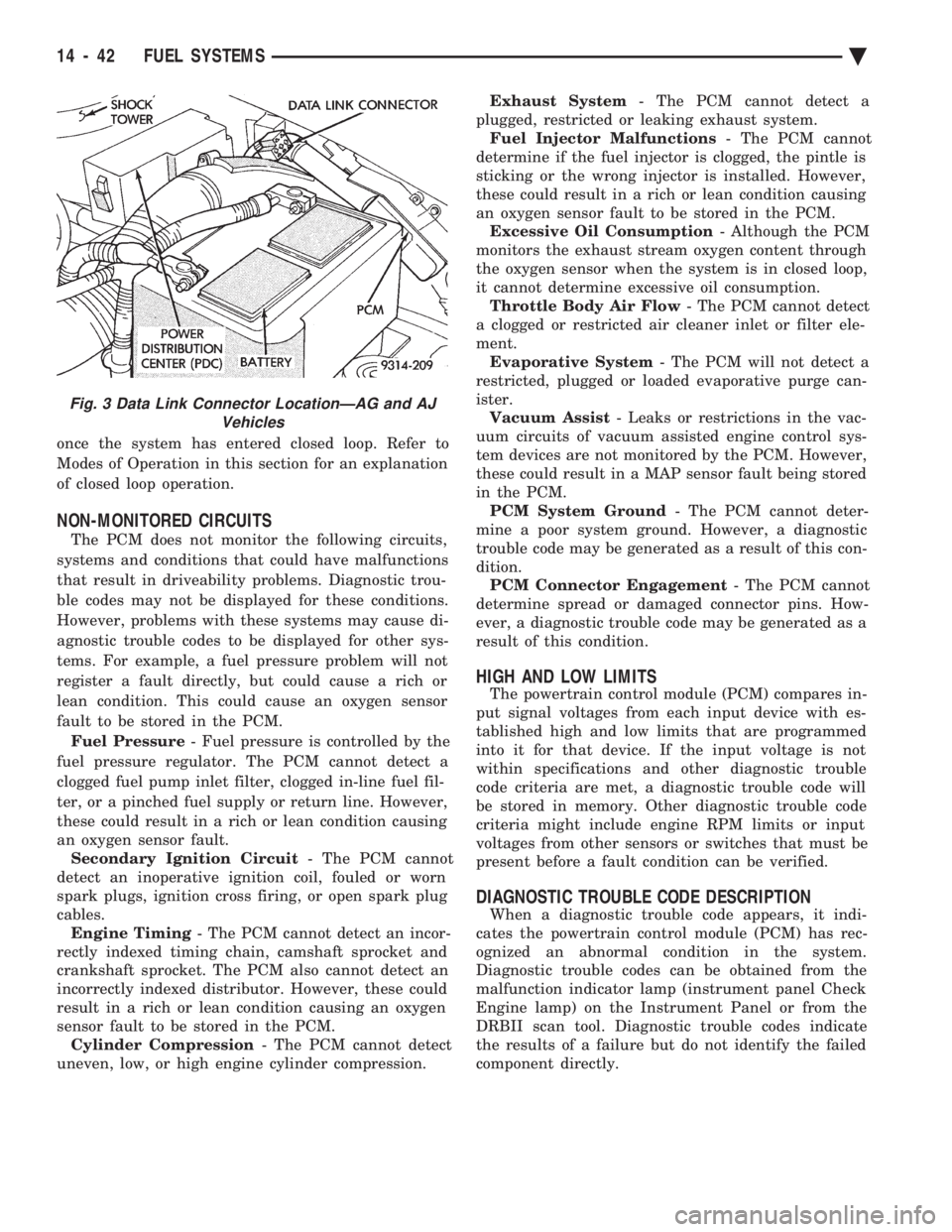
Fig. 3 Data Link Connector LocationÐAG and AJ Vehicles
14 - 42 FUEL SYSTEMS Ä