1993 CHEVROLET PLYMOUTH ACCLAIM power steering
[x] Cancel search: power steeringPage 367 of 2438

(2) Adjust belt tension by applying torque to
square hole C on idler bracket. Adjust tension to
specification given in Belt Tension Chart. (3) Tighten in order, first, locking screws B then
pivot screw A to 54 N Im (40 ft. lbs.).
POWER STEERING PUMPÐS TYPE
(1) From on top of the vehicle loosen locking screw G.
(2) From under the vehicle loosen the pivot screw
and pivot nut H . (3) After installing a new belt adjust belt tension
with 1/2 in. breaker bar installed in adjusting
bracket. See tension specification in chart. (4) Tighten locking screw G to 54 N Im (40 ft. lbs.).
(5) Tighten pivot screw H and the pivot nut to 54
N Im (40 ft. lbs.)
GENERATOR BELT
(1) Loosen T-Bolt locking nut E and adjusting
screw F to remove and install Poly V belt and/or ad-
just belt tension. (2) Tighten adjusting screw F to adjust belt tension
to specification shown in Belt Tension Chart. (3) Tighten T-Bolt locking nut E to 54 N Im (40 ft.
lbs.).
3.0L ENGINE BELTS REMOVE/INSTALL AND
ADJUST
AIR CONDITIONING BELT
To remove and install the air conditioning com-
pressor drive belt, first loosen the idler pulley lock
nut, then turn the adjusting screw to raise or lower
the idler pulley (Figs. 3 and 4).
To adjust the air conditioning drive belt, loosen
the idler pulley nut (Fig. 3) and adjust belt tension
Fig. 2 Accessory Drive BeltsÐ2.2 and 2.5L Engines
Fig. 3 Accessory Drive BeltsÐ3.0L Engine
Ä COOLING SYSTEM 7 - 25
Page 368 of 2438

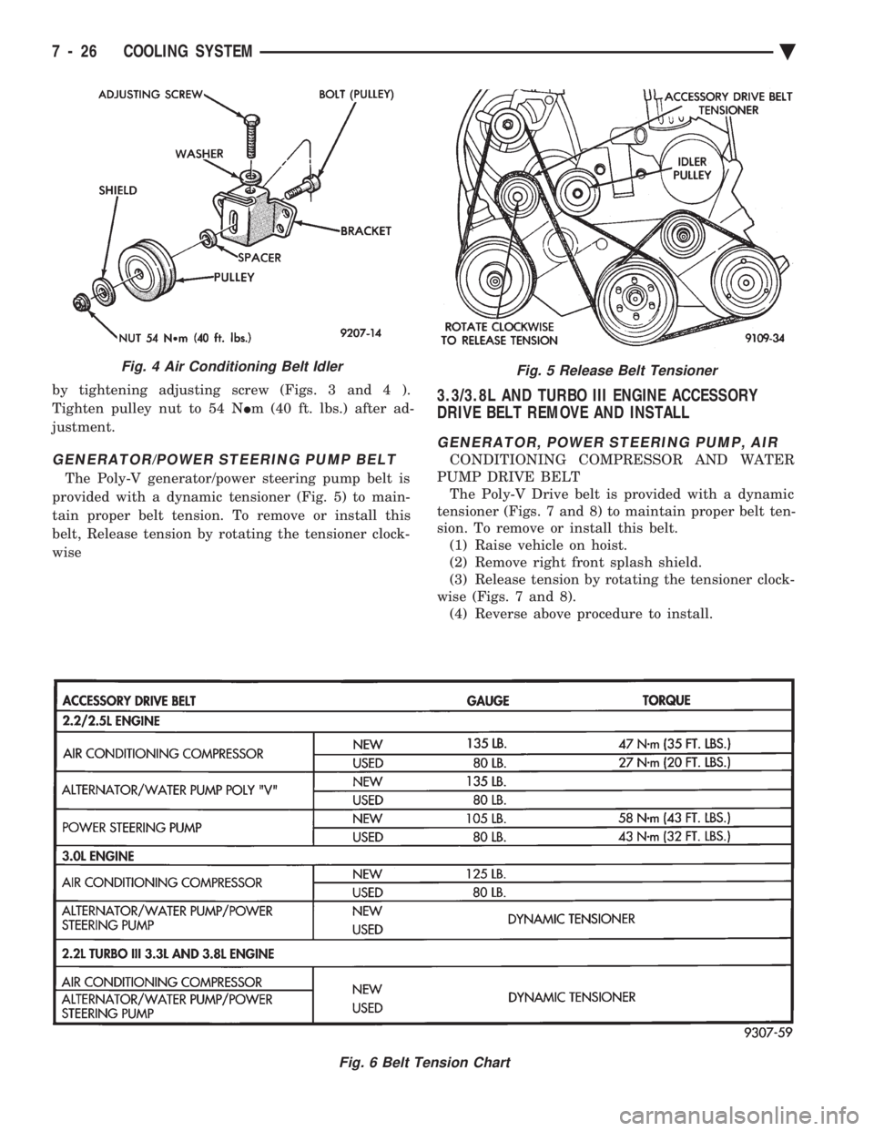
by tightening adjusting screw (Figs. 3 and 4 ).
Tighten pulley nut to 54 N Im (40 ft. lbs.) after ad-
justment.
GENERATOR/POWER STEERING PUMP BELT
The Poly-V generator/power steering pump belt is
provided with a dynamic tensioner (Fig. 5) to main-
tain proper belt tension. To remove or install this
belt, Release tension by rotating the tensioner clock-
wise
3.3/3.8L AND TURBO III ENGINE ACCESSORY
DRIVE BELT REMOVE AND INSTALL
GENERATOR, POWER STEERING PUMP, AIR
CONDITIONING COMPRESSOR AND WATER
PUMP DRIVE BELT The Poly-V Drive belt is provided with a dynamic
tensioner (Figs. 7 and 8) to maintain proper belt ten-
sion. To remove or install this belt. (1) Raise vehicle on hoist.
(2) Remove right front splash shield.
(3) Release tension by rotating the tensioner clock-
wise (Figs. 7 and 8). (4) Reverse above procedure to install.
Fig. 5 Release Belt Tensioner
Fig. 6 Belt Tension Chart
Fig. 4 Air Conditioning Belt Idler
7 - 26 COOLING SYSTEM Ä
Page 413 of 2438

(6) For installation, reverse above procedure.
Tighten all fasteners to the proper torque. Refer to
the Torque Specifications chart at the rear of this
group.
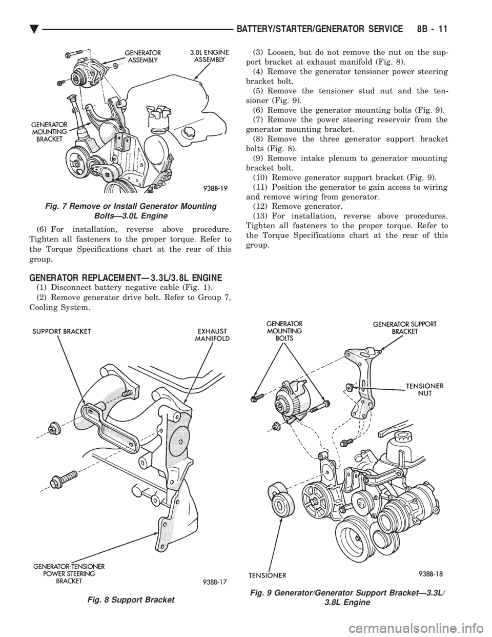
GENERATOR REPLACEMENTÐ3.3L/3.8L ENGINE
(1) Disconnect battery negative cable (Fig. 1).
(2) Remove generator drive belt. Refer to Group 7,
Cooling System. (3) Loosen, but do not remove the nut on the sup-
port bracket at exhaust manifold (Fig. 8). (4) Remove the generator tensioner power steering
bracket bolt. (5) Remove the tensioner stud nut and the ten-
sioner (Fig. 9). (6) Remove the generator mounting bolts (Fig. 9).
(7) Remove the power steering reservoir from the
generator mounting bracket. (8) Remove the three generator support bracket
bolts (Fig. 8). (9) Remove intake plenum to generator mounting
bracket bolt. (10) Remove generator support bracket (Fig. 9).
(11) Position the generator to gain access to wiring
and remove wiring from generator. (12) Remove generator.
(13) For installation, reverse above procedures.
Tighten all fasteners to the proper torque. Refer to
the Torque Specifications chart at the rear of this
group.
Fig. 7 Remove or Install Generator Mounting BoltsÐ3.0L Engine
Fig. 8 Support BracketFig. 9 Generator/Generator Support BracketÐ3.3L/ 3.8L Engine
Ä BATTERY/STARTER/GENERATOR SERVICE 8B - 11
Page 517 of 2438

off, there should be continuity in the system. Start
the engine. With the engine running, the ohmmeter
should show no continuity. If the above results are
not obtained, replace the switch.
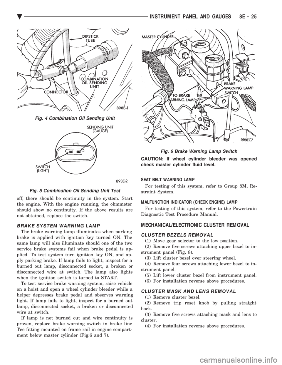
BRAKE SYSTEM WARNING LAMP
The brake warning lamp illuminates when parking
brake is applied with ignition key turned ON. The
same lamp will also illuminate should one of the two
service brake systems fail when brake pedal is ap-
plied. To test system turn ignition key ON, and ap-
ply parking brake. If lamp fails to light, inspect for a
burned out lamp, disconnected socket, a broken or
disconnected wire at switch. The lamp also lights
when the ignition switch is turned to START. To test service brake warning system, raise vehicle
on a hoist and open a wheel cylinder bleeder while a
helper depresses brake pedal and observes warning
light. If lamp fails to light, inspect for a burned out
lamp, disconnected socket, a broken or disconnected
wire at switch. If lamp is not burned out and wire continuity is
proven, replace brake warning switch in brake line
Tee fitting mounted on frame rail in engine compart-
ment below master cylinder (Fig.6 and 7). CAUTION: If wheel cylinder bleeder was opened
check master cylinder fluid level.
SEAT BELT WARNING LAMP
For testing of this system, refer to Group 8M, Re-
straint System.
MALFUNCTION INDICATOR (CHECK ENGINE) LAMP
For testing of this system, refer to the Powertrain
Diagnostic Test Procedure Manual.
MECHANICAL/ELECTRONIC CLUSTER REMOVAL
CLUSTER BEZELS REMOVAL
(1) Move gear selector to the low position.
(2) Remove five screws attaching upper bezel to in-
strument panel (Fig. 8). (3) Lift cluster bezel over steering wheel.
(4) Remove four screws attaching lower bezel to in-
strument panel. (5) Lift lower cluster bezel from instrument panel.
(6) For installation reverse above procedures.
CLUSTER MASK AND LENS REMOVAL
(1) Remove cluster bezel.
(2) Remove trip reset knob by pulling straight
back. (3) Remove five screws attaching mask and lens to
cluster. (4) For installation reverse above procedures.
Fig. 4 Combination Oil Sending Unit
Fig. 5 Combination Oil Sending Unit Test
Fig. 6 Brake Warning Lamp Switch
Ä INSTRUMENT PANEL AND GAUGES 8E - 25
Page 535 of 2438

ELECTRONIC DIGITAL CLOCK
The electronic digital clock is in the radio. The
clock and radio each use the display panel built into
the radio. A digital readout indicates the time in
hours and minutes whenever the ignition switch is in
the ON or ACC position. When the ignition switch is in the ON or OFF po-
sition, or when the radio frequency is being dis-
played, time keeping is accurately maintained. The procedure for setting the clock varies slightly
with each radio. The correct procedure is described
under the individual radio operating instructions re-
ferred to in the Owner's manual supplied with the
vehicle.
WARNING LAMPS
The AG & AJ Body instrument clusters have warn-
ing lamps or indicators with the electronic cluster for
six different systems. These include low oil pressure,
check gauges, brake system, air bag, seat belt, mal-
function indicator (check engine) lamp.
CLUSTER AND GAUGE SERVICE AND TESTING
CAUTION: Disconnect negative battery cable, in en-
gine compartment, before servicing instrument
panel. When power is required for test purposes,
reconnect battery cable for test only. Disconnect negative battery cable after test and be-
fore continuing service procedures. It is not necessary to remove instrument cluster
from vehicle for gauge replacement. Gauges must be pulled straight out, when remov-
ing or pins may be damaged.
SWITCH POD ASSEMBLY REMOVAL
(1) Disconnect negative battery cable.
(2) Pry up edge of panel vent grille, using a
straight flat edge tool to disengage clips, then re-
move grille (Fig. 4). (3) Remove two screws located under panel vent
grille. (4) Remove two screws underneath switch POD as-
sembly. (5) With tilt steering adjust steering wheel to the
lowest setting. (6) Pull switch module rearward to remove module
and disconnect all wire connections. (7) For Installation reverse above procedures.
Tighten all screws to 2 N Im (20 in. lbs.) torque.
MECHANICAL/ELECTRONIC CLUSTER REMOVAL
CLUSTER MASK AND LENS REMOVAL
(1) Remove switch pod assembly (Fig. 4).
(2) Remove tilt column lever if equipped.
(3) Remove steering column trim cover.
Fig. 4 Switch POD Assembly
Ä INSTRUMENT PANEL AND GAUGES 8E - 43
Page 538 of 2438

(f) If there is a difference in readings, check
printed circuit board for contact to cluster connec-
tors. (g) If OK and contacts are not distorted, replace
printed circuit board. (h) If everything checks out OK, refer to Sending
Unit Test.
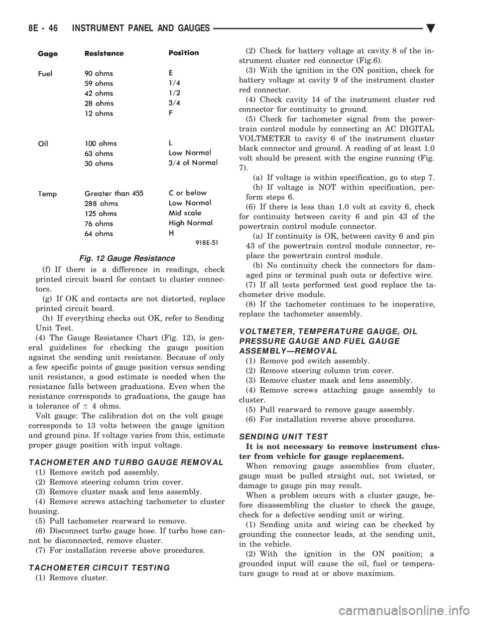
(4) The Gauge Resistance Chart (Fig. 12), is gen-
eral guidelines for checking the gauge position
against the sending unit resistance. Because of only
a few specific points of gauge position versus sending
unit resistance, a good estimate is needed when the
resistance falls between graduations. Even when the
resistance corresponds to graduations, the gauge has
a tolerance of 64 ohms.
Volt gauge: The calibration dot on the volt gauge
corresponds to 13 volts between the gauge ignition
and ground pins. If voltage varies from this, estimate
proper gauge position with input voltage.
TACHOMETER AND TURBO GAUGE REMOVAL
(1) Remove switch pod assembly.
(2) Remove steering column trim cover.
(3) Remove cluster mask and lens assembly.
(4) Remove screws attaching tachometer to cluster
housing. (5) Pull tachometer rearward to remove.
(6) Disconnect turbo gauge hose. If turbo hose can-
not be disconnected, remove cluster. (7) For installation reverse above procedures.
TACHOMETER CIRCUIT TESTING
(1) Remove cluster. (2) Check for battery voltage at cavity 8 of the in-
strument cluster red connector (Fig.6). (3) With the ignition in the ON position, check for
battery voltage at cavity 9 of the instrument cluster
red connector. (4) Check cavity 14 of the instrument cluster red
connector for continuity to ground. (5) Check for tachometer signal from the power-
train control module by connecting an AC DIGITAL
VOLTMETER to cavity 6 of the instrument cluster
black connector and ground. A reading of at least 1.0
volt should be present with the engine running (Fig.
7). (a) If voltage is within specification, go to step 7.
(b) If voltage is NOT within specification, per-
form steps 6.
(6) If there is less than 1.0 volt at cavity 6, check
for continuity between cavity 6 and pin 43 of the
powertrain control module connector. (a) If continuity is OK, between cavity 6 and pin
43 of the powertrain control module connector, re-
place the powertrain control module. (b) No continuity check the connectors for dam-
aged pins or terminal push outs or defective wire.
(7) If all tests performed test good replace the ta-
chometer drive module. (8) If the tachometer continues to be inoperative,
replace the tachometer assembly.
VOLTMETER, TEMPERATURE GAUGE, OIL PRESSURE GAUGE AND FUEL GAUGEASSEMBLYÐREMOVAL
(1) Remove pod switch assembly.
(2) Remove steering column trim cover.
(3) Remove cluster mask and lens assembly.
(4) Remove screws attaching gauge assembly to
cluster. (5) Pull rearward to remove gauge assembly.
(6) For installation reverse above procedures.
SENDING UNIT TEST
It is not necessary to remove instrument clus-
ter from vehicle for gauge replacement. When removing gauge assemblies from cluster,
gauge must be pulled straight out, not twisted, or
damage to gauge pin may result. When a problem occurs with a cluster gauge, be-
fore disassembling the cluster to check the gauge,
check for a defective sending unit or wiring. (1) Sending units and wiring can be checked by
grounding the connector leads, at the sending unit,
in the vehicle. (2) With the ignition in the ON position; a
grounded input will cause the oil, fuel or tempera-
ture gauge to read at or above maximum.
Fig. 12 Gauge Resistance
8E - 46 INSTRUMENT PANEL AND GAUGES Ä
Page 559 of 2438

VEHICLE SPEED SENSOR TEST
For testing of the vehicle speed sensor and related
components using DRB II, refer to the appropriate
Powertrain Diagnostics Test Procedure Manual.
PRINTED CIRCUIT BOARD REPLACEMENT
(1) Remove cluster bezel.
(2) Remove instrument cluster.
(3) Remove tachometer drive module, if equipped.
(4) Remove six retaining screws (Fig. 18).
(5) Twist out all illumination and warning lamp
sockets. (6) Pull printed circuit board from cluster housing.
(7) For installation reverse above procedures. Posi-
tion printed circuit board on cluster housing, being
certain that all gauge pins are inserted correctly.
CLUSTER LAMP REPLACEMENT
Illumination Lamp Chart shows cluster as viewed
from rear. However, all lamps must be replaced by
removing cluster from instrument panel (Fig. 19).
SWITCH AND PANEL COMPONENT SERVICE
LOWER STEERING COLUMN COVER REPLACEMENT
(1) Disconnect park brake release rod from the
park brake handle. (2) Remove two screws attaching hood release (Fig.
20). (3) Remove fuse access door and remove steering
column cover attaching screw located directly above
the fuse block. (4) Remove six screws around outside of steering
column cover. (5) Remove steering column cover.
(6) For installation reverse above procedures.
CENTER MODULE LOWER COVER REPLACEMENT
(1) Open ash receiver and remove center module
bezel. (2) Remove module cover to instrument panel re-
taining screws (Fig. 20). (3) Remove module cover from vehicle.
(4) For installation reverse above procedures.
CENTER MODULE BEZEL REPLACEMENT
(1) Open ash receiver.
(2) Grip module bezel around outer edges and pull
rearward to release six spring-type retaining clips
(Fig. 20). (3) For installation position spring clips to instru-
ment panel and push firmly until seated. (4) Close ash receiver.
Fig. 17 Vehicle Speed Sensor Removal
Fig. 18 Printed Circuit Board
Fig. 19 Instrument Cluster Illumination Lamps
Ä INSTRUMENT PANEL AND GAUGES 8E - 67
Page 603 of 2438

VEHICLE SPEED CONTROL
CONTENTS
page page
CHECKING FOR FAULT CODE .............. 3
DIAGNOSIS PROCEDURES ................ 2
GENERAL INFORMATION .................. 1
INOPERATIVE SYSTEM ................... 3
POWERTRAIN CONTROL MODULE ELECTRICAL TEST ................................ 5
ROAD TEST ............................ 2
SERVO ELECTRICAL TESTS ............... 4
SERVO UNIT ............................ 9 SERVO VACUUM TEST
................... 9
STOP LAMP VEHICLE SPEED CONTROL SWITCH TEST ......................... 8
VACUUM SUPPLY TEST .................. 9
VEHICLE SPEED CONTROL SWITCH REMOVAL ........................... 10
VEHICLE SPEED CONTROL SWITCH TEST . . . 8
VEHICLE SPEED CONTROL ELECTRICAL TESTS ............................... 3
GENERAL INFORMATION
The vehicle speed control is electronically con-
trolled and vacuum operated. The electronic control
is integrated into the powertrain control module, lo-
cated next to battery. The controls are located on the
steering wheel and consist of the ON/OFF, RESUME/
ACCEL and SET/DECEL buttons (Fig. 1). For iden-
tification and location of the major components (Fig.
2 through 8).
The system is designed to operate at speeds above
35 mph (50 km/h).
WARNING: THE USE OF VEHICLE SPEED CON-
TROL IS NOT RECOMMENDED WHEN DRIVING
CONDITIONS DO NOT PERMIT MAINTAINING A
CONSTANT SPEED, SUCH AS IN HEAVY TRAFFIC
OR ON ROADS THAT ARE WINDING, ICY, SNOW
COVERED, OR SLIPPERY.
TO ACTIVATE: The ON/OFF button to the de-
pressed latched position, ON, the vehicle speed con-
trol function is now ready for use. TO DEACTIVATE:
A soft tap of the brake pedal,
normal brake application or depressing the clutch
pedal while the system is engaged will disengage ve-
hicle speed control without erasing memory. A sud-
den increase in engine rpm may be experienced if the
clutch pedal is depressed while the vehicle speed con-
trol is engaged. Pushing the ON/OFF button to the
unlatched position or turning off the ignition erases
the memory. TO SET SPEED: When the vehicle has reached
the desired speed push the SET/DECEL button to en-
gage system which will then automatically maintain
the desired speed. TO DECELERATE: When vehicle speed control is
engaged, holding the SET/DECEL button depressed
allows the vehicle to coast to a lower speed setting.
Fig. 1 Vehicle Speed Control Switch
Fig. 2 Vehicle Speed ControlÐ2.2L and 2.5L
Ä VEHICLE SPEED CONTROL 8H - 1