1993 CHEVROLET PLYMOUTH ACCLAIM fuel cap
[x] Cancel search: fuel capPage 1715 of 2438
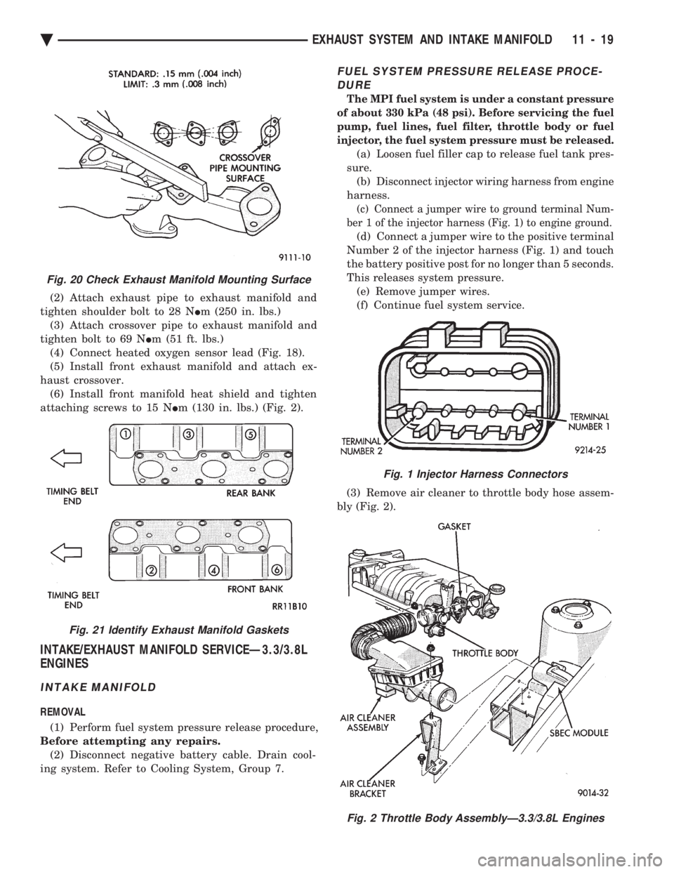
(2) Attach exhaust pipe to exhaust manifold and
tighten shoulder bolt to 28 N Im (250 in. lbs.)
(3) Attach crossover pipe to exhaust manifold and
tighten bolt to 69 N Im (51 ft. lbs.)
(4) Connect heated oxygen sensor lead (Fig. 18).
(5) Install front exhaust manifold and attach ex-
haust crossover. (6) Install front manifold heat shield and tighten
attaching screws to 15 N Im (130 in. lbs.) (Fig. 2).
INTAKE/EXHAUST MANIFOLD SERVICEÐ3.3/3.8L
ENGINES
INTAKE MANIFOLD
REMOVAL
(1) Perform fuel system pressure release procedure,
Before attempting any repairs. (2) Disconnect negative battery cable. Drain cool-
ing system. Refer to Cooling System, Group 7.
FUEL SYSTEM PRESSURE RELEASE PROCE- DURE
The MPI fuel system is under a constant pressure
of about 330 kPa (48 psi). Before servicing the fuel
pump, fuel lines, fuel filter, throttle body or fuel
injector, the fuel system pressure must be released.
(a) Loosen fuel filler cap to release fuel tank pres-
sure. (b) Disconnect injector wiring harness from engine
harness.
(c) Connect a jumper wire to ground terminal Num-
ber 1 of the injector harness (Fig. 1) to engine ground.
(d) Connect a jumper wire to the positive terminal
Number 2 of the injector harness (Fig. 1) and touch
the battery positive post for no longer than 5 seconds.
This releases system pressure. (e) Remove jumper wires.
(f) Continue fuel system service.
(3) Remove air cleaner to throttle body hose assem-
bly (Fig. 2).
Fig. 20 Check Exhaust Manifold Mounting Surface
Fig. 21 Identify Exhaust Manifold Gaskets
Fig. 1 Injector Harness Connectors
Fig. 2 Throttle Body AssemblyÐ3.3/3.8L Engines
Ä EXHAUST SYSTEM AND INTAKE MANIFOLD 11 - 19
Page 1741 of 2438
FUEL SYSTEMS
CONTENTS
page page
2.2L TURBO III MULTI-PORT FUEL INJECTIONÐ GENERAL DIAGNOSIS ................. 95
2.2L TURBO III MULTI-PORT FUEL INJECTIONÐ ON-BOARD DIAGNOSTICS ............. 100
2.2L TURBO III MULTI-PORT FUEL INJECTIONÐ SERVICE PROCEDURES ............... 107
2.2L TURBO III MULTI-PORT FUEL INJECTIONÐ SYSTEM OPERATION .................. 83
2.2L/2.5L SINGLE POINT FUEL INJECTIONÐ GENERAL DIAGNOSIS .................. 35
2.2L/2.5L SINGLE POINT FUEL INJECTIONÐ ON-BOARD DIAGNOSTICS .............. 41
2.2L/2.5L SINGLE POINT FUEL INJECTIONÐ SERVICE PROCEDURES ................ 48
2.2L/2.5L SINGLE POINT FUEL INJECTIONÐ SYSTEM OPERATION .................. 24
2.5L FLEXIBLE FUEL MULTI-PORT FUEL INJECTIONÐGENERAL DIAGNOSIS ....... 66
2.5L FLEXIBLE FUEL MULTI-PORT FUEL INJECTIONÐON-BOARD DIAGNOSTICS . . . 70
2.5L FLEXIBLE FUEL MULTI-PORT FUEL INJECTIONÐSERVICE PROCEDURES ..... 77
2.5L FLEXIBLE FUEL MULTI-PORT FUEL INJECTIONÐSYSTEM OPERATION ....... 55 3.0L MULTI-PORT FUEL INJECTIONÐ
GENERAL DIAGNOSIS ................. 125
3.0L MULTI-PORT FUEL INJECTIONÐ ON-BOARD DIAGNOSTICS ............. 130
3.0L MULTI-PORT FUEL INJECTIONÐ SERVICE PROCEDURES ............... 138
3.0L MULTI-PORT FUEL INJECTIONÐ SYSTEM OPERATION ................. 113
3.3L AND 3.8L MULTI-PORT FUEL INJECTIONÐ GENERAL DIAGNOSIS ................. 157
3.3L AND 3.8L MULTI-PORT FUEL INJECTIONÐ ON-BOARD DIAGNOSTICS ............. 162
3.3L AND 3.8L MULTI-PORT FUEL INJECTIONÐ SERVICE PROCEDURES ............... 169
3.3L AND 3.8L MULTI-PORT FUEL INJECTIONÐ SYSTEM OPERATION ................. 145
ACCELERATOR PEDAL AND THROTTLE CABLE .............................. 21
FUEL DELIVERY SYSTEM ................. 3
FUEL TANKS .......................... 14
GENERAL INFORMATION .................. 1
SPECIFICATIONS ...................... 178
GENERAL INFORMATION
Throughout this group, references are made to a
particular vehicle by letter designation. A chart
showing the breakdown of these designations is in-
cluded in the Introduction Section at the front of this
service manual. The Fuel System consists of the fuel tank, fuel
pump, fuel filter, throttle body, fuel injectors, fuel
tubes and vacuum tubes. The Fuel Delivery System consists of the fuel
pump, fuel filter, fuel lines and fuel hoses. The Fuel Tank Assembly consists of the fuel tank,
filler tube, a fuel gauge sending unit assembly and a
pressure-vacuum filler cap. Also, the Evaporation Control System is part of the
fuel system. The evaporation control system is de-
signed to reduce the emission of fuel vapor into the
atmosphere. The description and function of the Evaporation
Control System is found in Group 25 of this manual.FUEL REQUIREMENTS
Your vehicle was designed to meet all emission
regulations and provide excellent fuel economy when
using high quality unleaded gasoline.
VEHICLES WITHOUT TURBOCHARGED ENGINES
Use unleaded gasoline having a minimum octane
rating of 87.
VEHICLES WITH TURBOCHARGED ENGINESÐEXCEPT 16 VALVE 2.2L ENGINES
These vehicles will operate satisfactorily on both
regular unleaded gasoline having a minimum octane
rating or 87, and premium unleaded gasoline having
a minimum octane rating of 91. The use of premium
unleaded gasoline will improve performance.
VEHICLES WITH 2.2L 16 VALVE ENGINES
The use of premium unleaded gasoline having a
minimum octane of 91 is recommended. If premium
unleaded is not available, then unleaded gasoline
Ä FUEL SYSTEMS 14 - 1
Page 1743 of 2438
FUEL DELIVERY SYSTEM INDEX
page page
Chassis Fuel Tubes ...................... 11
Flexible Fuel Components ................... 3
Fuel FilterÐAll Vehicles .................... 9
Fuel Hoses, Clamps, and Quick Connect Fittings . 10
Fuel Pump Assembly ...................... 5
Fuel Pump Module Installation ............... 9
Fuel Pump Module Removal ................. 8
Fuel Pump Pressure TestÐ2.2L/2.5L TBI and 3.0L MPI Engines ........................... 7
Fuel Pump Pressure TestÐAll Except 2.2L/2.5L TBI and 3.0L MPI ....................... 6
Fuel Pump Strainer Service .................. 9 Fuel System Pressure
...................... 6
Fuel System Pressure Release ProcedureÐ 2.2L/2.5L TBI ........................... 4
Fuel System Pressure Release ProcedureÐ3.0L . . 5
Fuel System Pressure Release ProcedureÐExcept 2.2L/2.5L TBI and 3.0L ................... 4
General Information ........................ 3
Identifying Flexible Fuel Components .......... 3
Mechanical Malfunctions .................... 8
Methanol Concentration SensorÐFlexible Fuel AA-Body .............................. 4
Service Precautions for Flexible Fuel Vehicles .... 3
GENERAL INFORMATION
Beginning this model year, Chrysler began produc-
ing AA-Body vehicles designed to operate on a mix-
ture of gasoline and methanol. These automobiles are
referred to as Flexible Fuel vehicles. Flexible fuel vehicles can operate on a mixture of
up to 85 percent methanol, 15 percent unleaded gas-
oline. These vehicles also operate on mixtures con-
taining a lower percentage of methanol or just pure
unleaded gasoline. In many cases, the procedures for servicing flexible
fuel components is identical to gasoline only compo-
nents. Refer to the particular Service Procedure in
this section. If the service procedure for flexible fuel
component differs from a gasoline only component,
the title of each service procedure identifies the ap-
plication.
SERVICE PRECAUTIONS FOR FLEXIBLE FUEL
VEHICLES
Methanol is more toxic than gasoline. Always re-
lease fuel system pressure before servicing fuel sys-
tem components and wear methanol resistant gloves
and eye protection. Avoid breathing methanol vapors or ingesting
methanol. Headaches, dizziness and even uncon-
sciousness could result from breathing these vapors.
Serious injury, blindness and even death could result
from ingesting methanol. Methanol vapors are extremely flammable and can
travel along the ground. Service vehicles in well ven-
tilated areas and avoid ignition sources. Never
smoke while servicing the vehicle. Do not allow methanol to contact skin. Prolonged
contact with methanol can cause dry skin or an al-
lergic skin reaction. Also, prolonged contact could re-
sult in absorption through the skin.
IDENTIFYING FLEXIBLE FUEL COMPONENTS
Flexible Fuel vehicles have unique methanol com-
patible fuel system components. Chrysler identifies
methanol compatible components that could be phys-
ically interchanged with gasoline only parts by color-
ing them green or applying a green label or tag to
them. Even though they may appear physically iden-
tical, components for gasoline only vehicles must not
be used on flexible fuel vehicles.
FLEXIBLE FUEL COMPONENTS
Flexible fuel AA-body vehicles uses many unique
fuel system components. The unique parts are green
in appearance or have a green tag or label attached
to them. While components used on gasoline only ve-
hicles may look similar or identical, they cannot be
used on flexible fuel vehicles. When servicing a com-
ponent, always use an original equipment or equiva-
lent flexible fuel replacement. The fuel system of flexible fuel AA-body vehicles
have the following unique components.
² Fuel pump module
² Fuel level sensor
² Fuel gauge (gauge cluster).
² Fuel tank
² Fuel pressure regulator (including O-rings)
² Fuel rail
² Fuel injectors (including O-rings)
² Fuel tubes
² Fuel filter
² EVAP canister
² Fuel filler cap
² Fuel filler tube
² Pressure relief/Rollover valve
² All fuel system and emission system hoses and
tubes
Ä FUEL SYSTEMS 14 - 3
Page 1744 of 2438
INSTRUMENT PANEL CLUSTER IDENTIFICATIONÐFLEXIBLE FUEL AA-BODY
Flexible fuel A-Body vehicles use a unique gauge
cluster. To identify the cluster, remove it from the
instrument panel and check the number on the tag
on the top. If the part number matches the number
in the parts book for flexible fuel A-bodies, the vehi-
cle was built with the correct cluster. Refer to Group
8E, Instrument Panel and Gauges, for cluster re-
moval and installation.
METHANOL CONCENTRATION SENSORÐFLEXIBLE
FUEL AA-BODY
The methanol concentration sensor contains a mi-
croprocessor that determines the percentage of gaso-
line and methanol in the fuel system. From the
methanol concentration sensor input, the powertrain
control module (PCM) determines the amount of
methanol in the fuel. The vehicle can operate on a
mixtures up to 85 percent methanol, 15 percent gas-
oline. The methanol concentration sensor output voltages
varies with the percent of methanol in the fuel sys-
tem. The sensor output voltage (input for PCM)
ranges from 0.5 volts for pure gasoline to 4.75 volts
for 85 percent methanol. For two seconds at key ON
when the operator starts the vehicle, the sensor cal-
ibrates the PCM. During the calibration period the
sensor sends 4.45 volts to the PCM as a correction
factor. The methanol concentration sensor has a built-in
shutdown capability. If the sensor shuts down, it de-
faults to the previous learned value (output voltage
based on methanol percentage of fuel). The methanol concentration sensor attaches to a
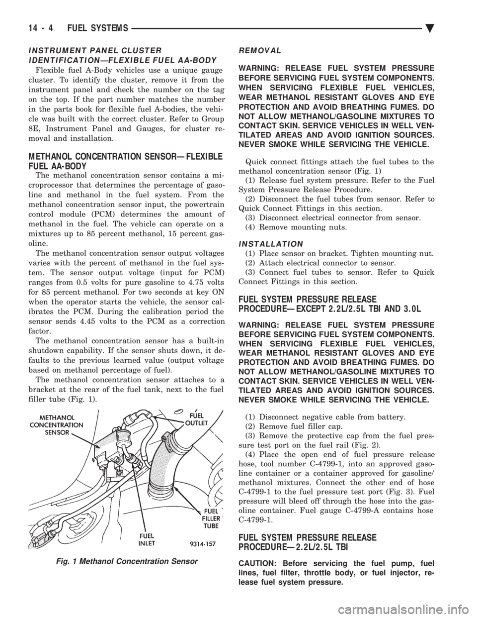
bracket at the rear of the fuel tank, next to the fuel
filler tube (Fig. 1).
REMOVAL
WARNING: RELEASE FUEL SYSTEM PRESSURE
BEFORE SERVICING FUEL SYSTEM COMPONENTS.
WHEN SERVICING FLEXIBLE FUEL VEHICLES,
WEAR METHANOL RESISTANT GLOVES AND EYE
PROTECTION AND AVOID BREATHING FUMES. DO
NOT ALLOW METHANOL/GASOLINE MIXTURES TO
CONTACT SKIN. SERVICE VEHICLES IN WELL VEN-
TILATED AREAS AND AVOID IGNITION SOURCES.
NEVER SMOKE WHILE SERVICING THE VEHICLE.
Quick connect fittings attach the fuel tubes to the
methanol concentration sensor (Fig. 1) (1) Release fuel system pressure. Refer to the Fuel
System Pressure Release Procedure. (2) Disconnect the fuel tubes from sensor. Refer to
Quick Connect Fittings in this section. (3) Disconnect electrical connector from sensor.
(4) Remove mounting nuts.
INSTALLATION
(1) Place sensor on bracket. Tighten mounting nut.
(2) Attach electrical connector to sensor.
(3) Connect fuel tubes to sensor. Refer to Quick
Connect Fittings in this section.
FUEL SYSTEM PRESSURE RELEASE
PROCEDUREÐEXCEPT 2.2L/2.5L TBI AND 3.0L
WARNING: RELEASE FUEL SYSTEM PRESSURE
BEFORE SERVICING FUEL SYSTEM COMPONENTS.
WHEN SERVICING FLEXIBLE FUEL VEHICLES,
WEAR METHANOL RESISTANT GLOVES AND EYE
PROTECTION AND AVOID BREATHING FUMES. DO
NOT ALLOW METHANOL/GASOLINE MIXTURES TO
CONTACT SKIN. SERVICE VEHICLES IN WELL VEN-
TILATED AREAS AND AVOID IGNITION SOURCES.
NEVER SMOKE WHILE SERVICING THE VEHICLE.
(1) Disconnect negative cable from battery.
(2) Remove fuel filler cap.
(3) Remove the protective cap from the fuel pres-
sure test port on the fuel rail (Fig. 2). (4) Place the open end of fuel pressure release
hose, tool number C-4799-1, into an approved gaso-
line container or a container approved for gasoline/
methanol mixtures. Connect the other end of hose
C-4799-1 to the fuel pressure test port (Fig. 3). Fuel
pressure will bleed off through the hose into the gas-
oline container. Fuel gauge C-4799-A contains hose
C-4799-1.
FUEL SYSTEM PRESSURE RELEASE
PROCEDUREÐ2.2L/2.5L TBI
CAUTION: Before servicing the fuel pump, fuel
lines, fuel filter, throttle body, or fuel injector, re-
lease fuel system pressure.Fig. 1 Methanol Concentration Sensor
14 - 4 FUEL SYSTEMS Ä
Page 1745 of 2438
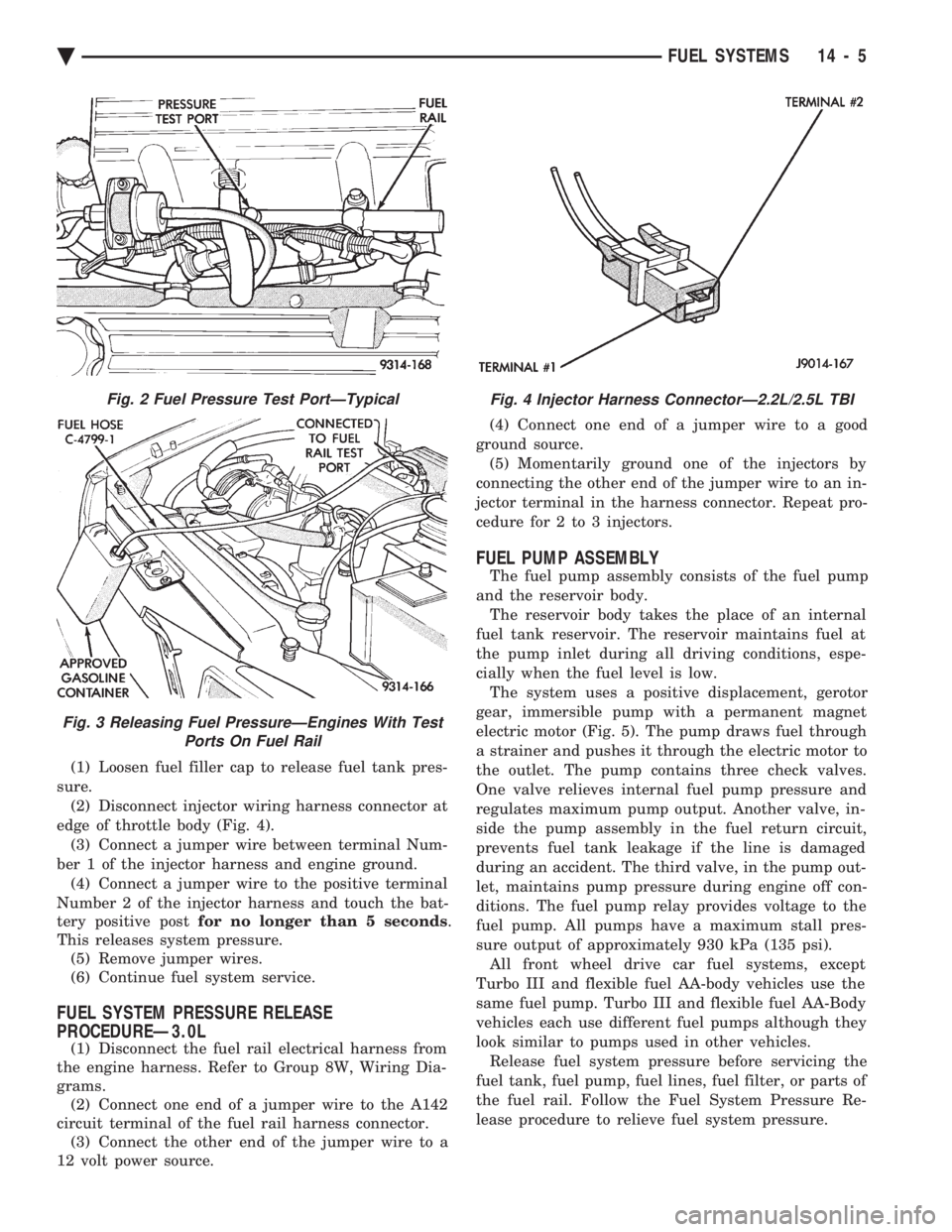
(1) Loosen fuel filler cap to release fuel tank pres-
sure. (2) Disconnect injector wiring harness connector at
edge of throttle body (Fig. 4). (3) Connect a jumper wire between terminal Num-
ber 1 of the injector harness and engine ground. (4) Connect a jumper wire to the positive terminal
Number 2 of the injector harness and touch the bat-
tery positive post for no longer than 5 seconds .
This releases system pressure. (5) Remove jumper wires.
(6) Continue fuel system service.
FUEL SYSTEM PRESSURE RELEASE
PROCEDUREÐ3.0L
(1) Disconnect the fuel rail electrical harness from
the engine harness. Refer to Group 8W, Wiring Dia-
grams. (2) Connect one end of a jumper wire to the A142
circuit terminal of the fuel rail harness connector. (3) Connect the other end of the jumper wire to a
12 volt power source. (4) Connect one end of a jumper wire to a good
ground source. (5) Momentarily ground one of the injectors by
connecting the other end of the jumper wire to an in-
jector terminal in the harness connector. Repeat pro-
cedure for 2 to 3 injectors.
FUEL PUMP ASSEMBLY
The fuel pump assembly consists of the fuel pump
and the reservoir body. The reservoir body takes the place of an internal
fuel tank reservoir. The reservoir maintains fuel at
the pump inlet during all driving conditions, espe-
cially when the fuel level is low. The system uses a positive displacement, gerotor
gear, immersible pump with a permanent magnet
electric motor (Fig. 5). The pump draws fuel through
a strainer and pushes it through the electric motor to
the outlet. The pump contains three check valves.
One valve relieves internal fuel pump pressure and
regulates maximum pump output. Another valve, in-
side the pump assembly in the fuel return circuit,
prevents fuel tank leakage if the line is damaged
during an accident. The third valve, in the pump out-
let, maintains pump pressure during engine off con-
ditions. The fuel pump relay provides voltage to the
fuel pump. All pumps have a maximum stall pres-
sure output of approximately 930 kPa (135 psi). All front wheel drive car fuel systems, except
Turbo III and flexible fuel AA-body vehicles use the
same fuel pump. Turbo III and flexible fuel AA-Body
vehicles each use different fuel pumps although they
look similar to pumps used in other vehicles. Release fuel system pressure before servicing the
fuel tank, fuel pump, fuel lines, fuel filter, or parts of
the fuel rail. Follow the Fuel System Pressure Re-
lease procedure to relieve fuel system pressure.
Fig. 2 Fuel Pressure Test PortÐTypical
Fig. 3 Releasing Fuel PressureÐEngines With Test Ports On Fuel Rail
Fig. 4 Injector Harness ConnectorÐ2.2L/2.5L TBI
Ä FUEL SYSTEMS 14 - 5
Page 1754 of 2438
FUEL TANKS INDEX
page page
Flexible Fuel Vehicles ..................... 14
Fuel Pump Module ....................... 18
Fuel Reservoir ........................... 18
Fuel System Pressure Release ProcedureÐ 2.2L/2.5L TBI .......................... 15
Fuel System Pressure Release ProcedureÐ3.0L . 15
Fuel System Pressure Release ProcedureÐ Except 2.2L/2.5L TBI and 3.0L ............. 15 Fuel Tank
.............................. 16
Fuel Tank Level Sensor ................... 18
Fuel Tank Pressure Relief and Roll-Over Valve . . 20
General Information ....................... 14
Identifying Flexible Fuel Components .......... 14
Methanol Concentration Sensor .............. 18
Pressure Vacuum Fuel Filler Tube Cap ........ 14
Service Precautions for Flexible Fuel Vehicles . . . 14
GENERAL INFORMATION
The fuel tanks of Chrysler Corporation built vehi-
cles are equipped with fuel and vapor controls that
allow the vehicle to pass a full 360É rollover. The fuel delivery system used on front wheel drive
vehicles contains a fuel tank pressure relief/rollover
valve. The valve mounts on the top of the fuel tank.
The valve functions as a pressure relief valve while
the vehicle is upright. The valve also contains a
check valve that prevents fuel from escaping the fuel
tank if the vehicle turns over. The fuel filler cap also acts as a pressure/vacuum
valve. When pressure inside the fuel tank gets too
high or too low, the fuel filler cap opens to relieve
the difference in air pressure. An evaporation control system restricts fuel evapo-
ration into the atmosphere and reduces unburned hy-
drocarbons. Vapors from the fuel tank are collected
in a charcoal filled canister. The vapors are held in
the canister until the engine is operating. When the
engine operates, vapors are drawn through the in-
take manifold into the combustion chambers.
FLEXIBLE FUEL VEHICLES
Beginning this model year, Chrysler began produc-
ing AA-Body vehicles designed to operate on a mix-
ture of gasoline and methanol. These automobiles are
referred to as Flexible Fuel Vehicles. Flexible fuel vehicles can operate on a mixture of
up to 85 percent methanol, 15 percent unleaded gas-
oline. These vehicles also operate on mixtures con-
taining a lower percentage of methanol or just pure
unleaded gasoline. In many cases, the procedures for servicing flexible
fuel components is identical to gasoline only compo-
nents. Refer to the particular Service Procedure in
this section. If the service procedure for flexible fuel
component differs from a gasoline only component,
the title of each service procedure identifies the ap-
plication.
IDENTIFYING FLEXIBLE FUEL COMPONENTS
Flexible Fuel vehicles have unique methanol com-
patible fuel system components. Chrysler identifies
methanol compatible components that could be phys-
ically interchanged with gasoline only parts by color-
ing them green or applying a green label or tag to
them. Even though they may appear physically iden-
tical, components for gasoline only AA-body vehicles
must not be used on flexible fuel vehicles.
SERVICE PRECAUTIONS FOR FLEXIBLE FUEL
VEHICLES
Methanol is more toxic than gasoline. Always re-
lease fuel system pressure before servicing fuel sys-
tem components and wear methanol resistant gloves
and eye protection. Avoid breathing methanol vapors or ingesting
methanol. Headaches, dizziness and even uncon-
sciousness could result from breathing these vapors.
Serious injury, blindness and even death could result
from ingesting methanol. Methanol vapors are extremely flammable and can
travel along the ground. Service vehicles in well ven-
tilated areas and avoid ignition sources. Never
smoke while servicing the vehicle. Do not allow methanol to contact skin. Prolonged
contact with methanol can cause dry skin or an al-
lergic skin reaction. Also, prolonged contact could re-
sult in absorption through the skin.
PRESSURE VACUUM FUEL FILLER TUBE CAP
WARNING: REMOVE FUEL FILLER TUBE CAP TO
RELIEVE TANK PRESSURE BEFORE REMOVING
OR REPAIRING FUEL SYSTEM COMPONENTS.
The loss of any fuel or vapor out of the filler tube
neck is prevented by the use of a safety filler cap.
The cap releases only under significant pressure 10.9
to 13.45 kPa (1.58 to 1.95 psi). The vacuum release
for all gas caps is between .97 and 2.0 kPa (.14 and
.29 psi). The cap must be replaced by a similar unit
in order for the system to remain effective.
14 - 14 FUEL SYSTEMS Ä
Page 1755 of 2438
WARNING: FUEL FILLER TUBE CAPS DESIGNED
FOR GASOLINE ONLY VEHICLES CANNOT BE
USED ON FLEXIBLE FUEL AA-BODY VEHICLES.
WHEN SERVICING THE FUEL SYSTEM OF A FLEX-
IBLE FUEL VEHICLE, ONLY USE ORIGINAL EQUIP-
MENT OR EQUIVALENT REPLACEMENT
COMPONENTS.
FUEL SYSTEM PRESSURE RELEASE
PROCEDUREÐEXCEPT 2.2L/2.5L TBI AND 3.0L
WARNING: RELEASE FUEL SYSTEM PRESSURE
BEFORE SERVICING FUEL SYSTEM COMPONENTS.
WHEN SERVICING FLEXIBLE FUEL VEHICLES,
WEAR METHANOL RESISTANT GLOVES AND EYE
PROTECTION AND AVOID BREATHING FUMES. DO
NOT ALLOW METHANOL/GASOLINE MIXTURES TO
CONTACT SKIN. SERVICE VEHICLES IN WELL VEN-
TILATED AREAS AND AVOID IGNITION SOURCES.
NEVER SMOKE WHILE SERVICING THE VEHICLE.
(1) Disconnect negative cable from battery.
(2) Remove fuel filler cap.
(3) Remove the protective cap from the fuel pres-
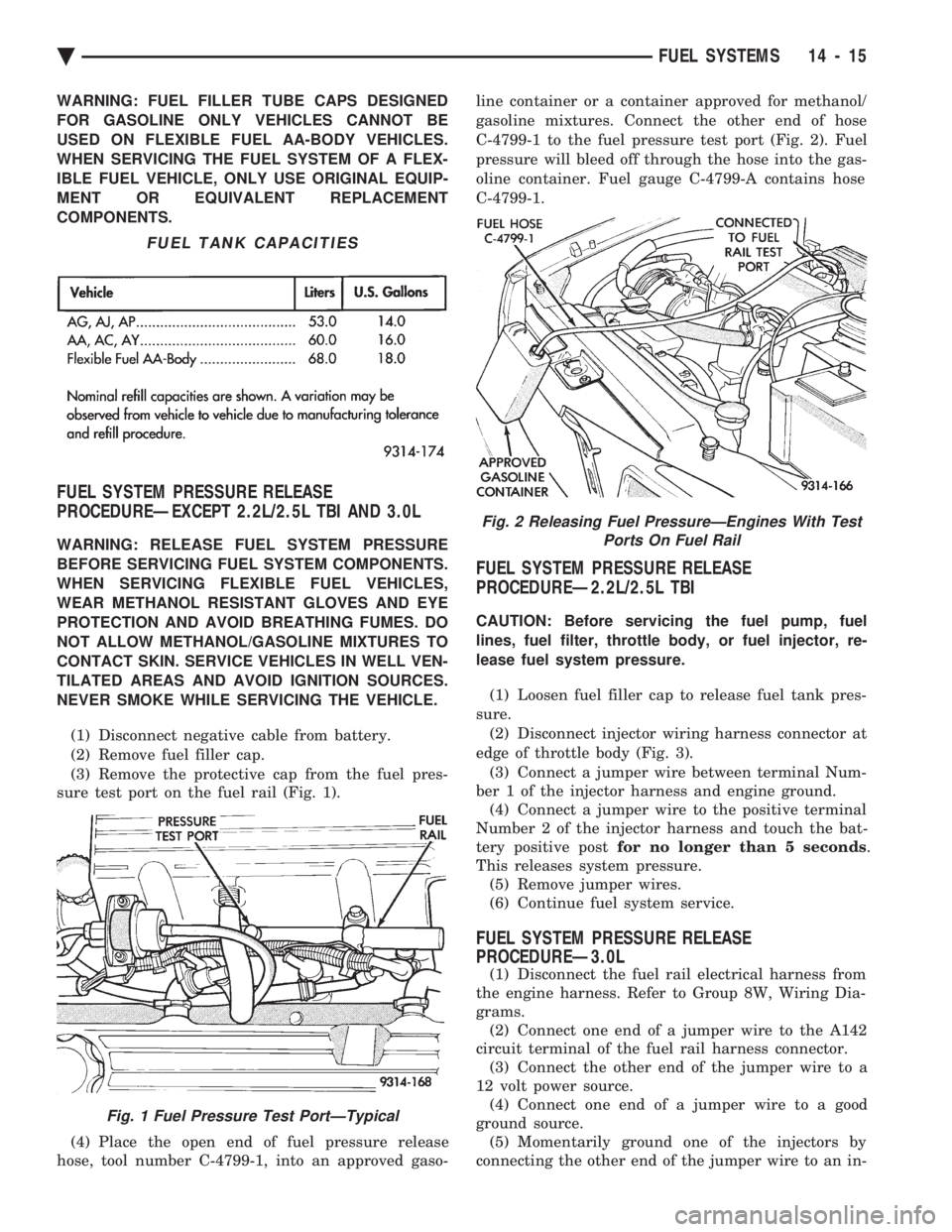
sure test port on the fuel rail (Fig. 1).
(4) Place the open end of fuel pressure release
hose, tool number C-4799-1, into an approved gaso- line container or a container approved for methanol/
gasoline mixtures. Connect the other end of hose
C-4799-1 to the fuel pressure test port (Fig. 2). Fuel
pressure will bleed off through the hose into the gas-
oline container. Fuel gauge C-4799-A contains hose
C-4799-1.
FUEL SYSTEM PRESSURE RELEASE
PROCEDUREÐ2.2L/2.5L TBI
CAUTION: Before servicing the fuel pump, fuel
lines, fuel filter, throttle body, or fuel injector, re-
lease fuel system pressure.
(1) Loosen fuel filler cap to release fuel tank pres-
sure. (2) Disconnect injector wiring harness connector at
edge of throttle body (Fig. 3). (3) Connect a jumper wire between terminal Num-
ber 1 of the injector harness and engine ground. (4) Connect a jumper wire to the positive terminal
Number 2 of the injector harness and touch the bat-
tery positive post for no longer than 5 seconds .
This releases system pressure. (5) Remove jumper wires.
(6) Continue fuel system service.
FUEL SYSTEM PRESSURE RELEASE
PROCEDUREÐ3.0L
(1) Disconnect the fuel rail electrical harness from
the engine harness. Refer to Group 8W, Wiring Dia-
grams. (2) Connect one end of a jumper wire to the A142
circuit terminal of the fuel rail harness connector. (3) Connect the other end of the jumper wire to a
12 volt power source. (4) Connect one end of a jumper wire to a good
ground source. (5) Momentarily ground one of the injectors by
connecting the other end of the jumper wire to an in-
FUEL TANK CAPACITIES
Fig. 1 Fuel Pressure Test PortÐTypical
Fig. 2 Releasing Fuel PressureÐEngines With Test Ports On Fuel Rail
Ä FUEL SYSTEMS 14 - 15
Page 1756 of 2438
jector terminal in the harness connector. Repeat pro-
cedure for 2 to 3 injectors.
FUEL TANK
DRAINING FUEL TANK
WARNING: RELEASE FUEL SYSTEM PRESSURE
BEFORE SERVICING FUEL SYSTEM COMPONENTS.
WHEN SERVICING FLEXIBLE FUEL VEHICLES,
WEAR METHANOL RESISTANT GLOVES AND EYE
PROTECTION AND AVOID BREATHING FUMES. DO
NOT ALLOW METHANOL/GASOLINE MIXTURES TO
CONTACT SKIN. SERVICE VEHICLES IN WELL VEN-
TILATED AREAS AND AVOID IGNITION SOURCES.
NEVER SMOKE WHILE SERVICING THE VEHICLE.
(1) Remove fuel filler cap.
(2) Perform the Fuel System Pressure Release pro-
cedure. (3) Remove ground cable from battery.
(4) Raise vehicle on hoist.
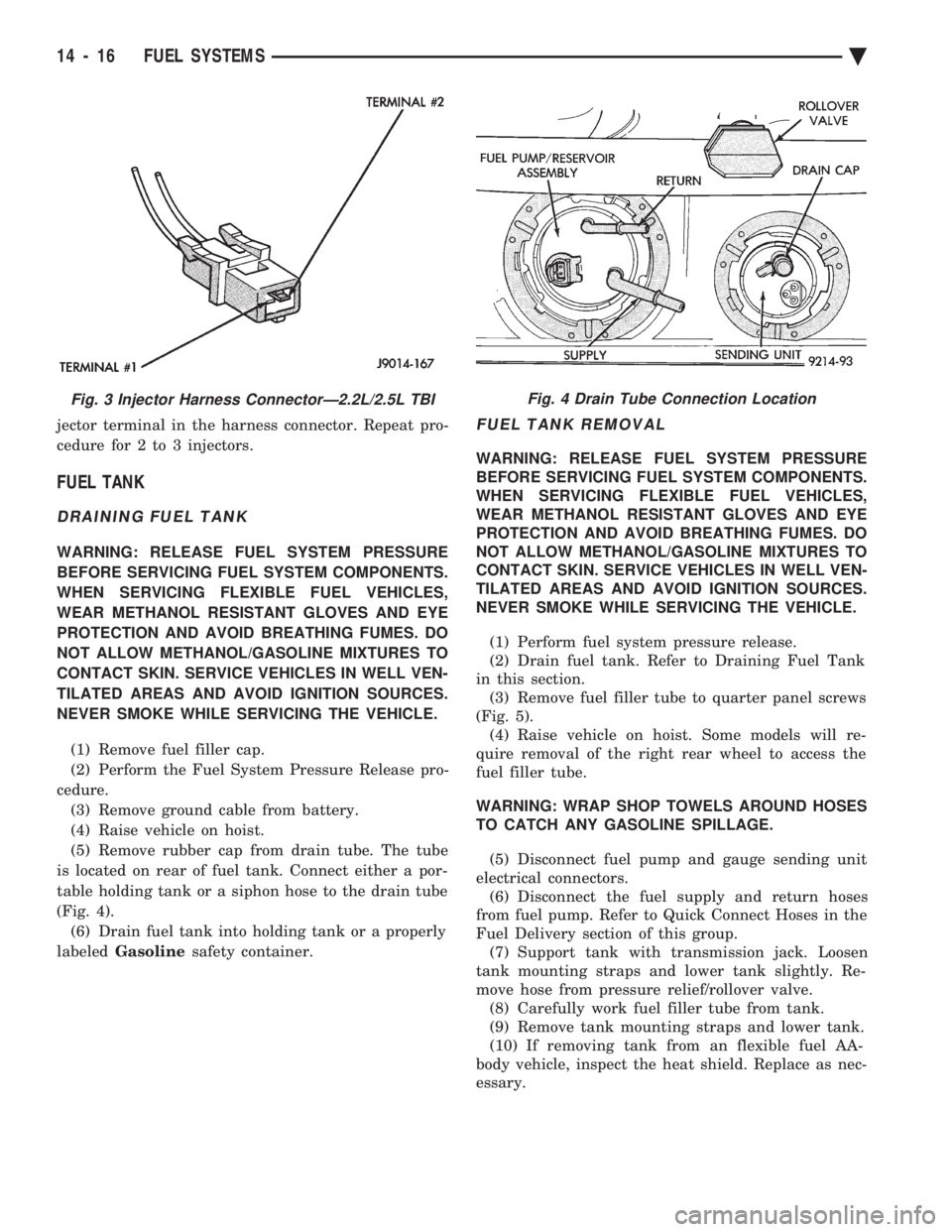
(5) Remove rubber cap from drain tube. The tube
is located on rear of fuel tank. Connect either a por-
table holding tank or a siphon hose to the drain tube
(Fig. 4). (6) Drain fuel tank into holding tank or a properly
labeled Gasoline safety container.
FUEL TANK REMOVAL
WARNING: RELEASE FUEL SYSTEM PRESSURE
BEFORE SERVICING FUEL SYSTEM COMPONENTS.
WHEN SERVICING FLEXIBLE FUEL VEHICLES,
WEAR METHANOL RESISTANT GLOVES AND EYE
PROTECTION AND AVOID BREATHING FUMES. DO
NOT ALLOW METHANOL/GASOLINE MIXTURES TO
CONTACT SKIN. SERVICE VEHICLES IN WELL VEN-
TILATED AREAS AND AVOID IGNITION SOURCES.
NEVER SMOKE WHILE SERVICING THE VEHICLE.
(1) Perform fuel system pressure release.
(2) Drain fuel tank. Refer to Draining Fuel Tank
in this section. (3) Remove fuel filler tube to quarter panel screws
(Fig. 5). (4) Raise vehicle on hoist. Some models will re-
quire removal of the right rear wheel to access the
fuel filler tube.
WARNING: WRAP SHOP TOWELS AROUND HOSES
TO CATCH ANY GASOLINE SPILLAGE.
(5) Disconnect fuel pump and gauge sending unit
electrical connectors. (6) Disconnect the fuel supply and return hoses
from fuel pump. Refer to Quick Connect Hoses in the
Fuel Delivery section of this group. (7) Support tank with transmission jack. Loosen
tank mounting straps and lower tank slightly. Re-
move hose from pressure relief/rollover valve. (8) Carefully work fuel filler tube from tank.
(9) Remove tank mounting straps and lower tank.
(10) If removing tank from an flexible fuel AA-
body vehicle, inspect the heat shield. Replace as nec-
essary.
Fig. 3 Injector Harness ConnectorÐ2.2L/2.5L TBIFig. 4 Drain Tube Connection Location
14 - 16 FUEL SYSTEMS Ä