1993 CHEVROLET PLYMOUTH ACCLAIM fuel cap
[x] Cancel search: fuel capPage 1909 of 2438

3.3L AND 3.8L MULTI-PORT FUEL INJECTIONÐSERVICE PROCEDURES INDEX
page page
Camshaft Position Sensor Service ........... 176
Crankshaft Position Sensor ................ 176
EVAP Canister Purge Solenoid Service ....... 175
Fuel Injector ........................... 174
Fuel Injector Rail Assembly ................ 170
Fuel Pressure Regulator .................. 173
Fuel System Pressure Release Procedure ..... 169 Heated Oxygen Sensor (O
2Sensor) Service . . . 177
Idle Air Control Motor .................... 170
Manifold Absolute Pressure (MAP) Sensor ..... 175
PCM Service ........................... 175
Throttle Body ........................... 169
Throttle Body Removal ................... 169
Throttle Position Sensor .................. 169
THROTTLE BODY REMOVAL
(1) Disconnect negative battery cable.
(2) Remove the air cleaner to throttle body hose
clamp. Remove the nut holding the air cleaner as-
sembly to the air cleaner bracket. Remove the air
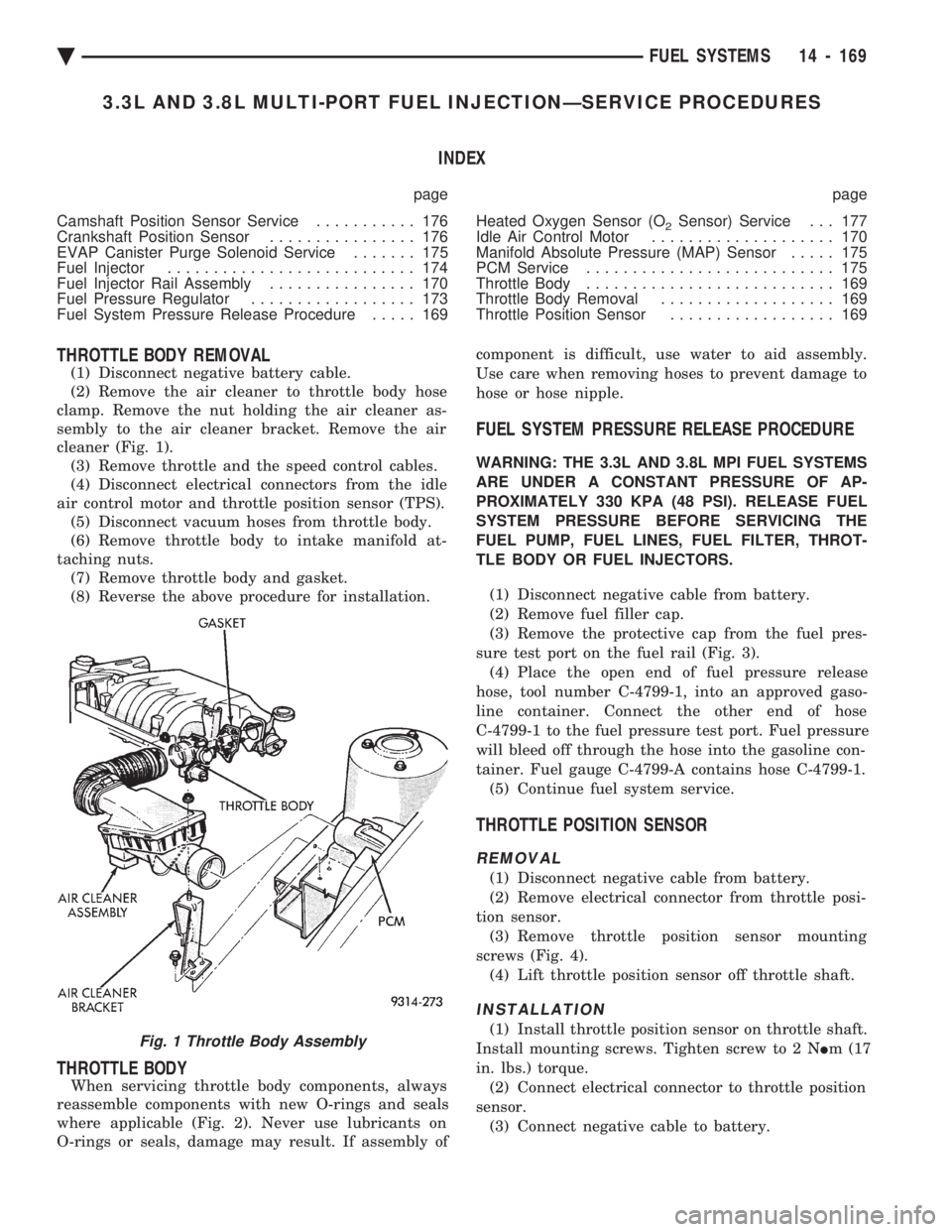
cleaner (Fig. 1). (3) Remove throttle and the speed control cables.
(4) Disconnect electrical connectors from the idle
air control motor and throttle position sensor (TPS). (5) Disconnect vacuum hoses from throttle body.
(6) Remove throttle body to intake manifold at-
taching nuts. (7) Remove throttle body and gasket.
(8) Reverse the above procedure for installation.
THROTTLE BODY
When servicing throttle body components, always
reassemble components with new O-rings and seals
where applicable (Fig. 2). Never use lubricants on
O-rings or seals, damage may result. If assembly of component is difficult, use water to aid assembly.
Use care when removing hoses to prevent damage to
hose or hose nipple.
FUEL SYSTEM PRESSURE RELEASE PROCEDURE
WARNING: THE 3.3L AND 3.8L MPI FUEL SYSTEMS
ARE UNDER A CONSTANT PRESSURE OF AP-
PROXIMATELY 330 KPA (48 PSI). RELEASE FUEL
SYSTEM PRESSURE BEFORE SERVICING THE
FUEL PUMP, FUEL LINES, FUEL FILTER, THROT-
TLE BODY OR FUEL INJECTORS.
(1) Disconnect negative cable from battery.
(2) Remove fuel filler cap.
(3) Remove the protective cap from the fuel pres-
sure test port on the fuel rail (Fig. 3). (4) Place the open end of fuel pressure release
hose, tool number C-4799-1, into an approved gaso-
line container. Connect the other end of hose
C-4799-1 to the fuel pressure test port. Fuel pressure
will bleed off through the hose into the gasoline con-
tainer. Fuel gauge C-4799-A contains hose C-4799-1. (5) Continue fuel system service.
THROTTLE POSITION SENSOR
REMOVAL
(1) Disconnect negative cable from battery.
(2) Remove electrical connector from throttle posi-
tion sensor. (3) Remove throttle position sensor mounting
screws (Fig. 4). (4) Lift throttle position sensor off throttle shaft.
INSTALLATION
(1) Install throttle position sensor on throttle shaft.
Install mounting screws. Tighten screw to 2 N Im (17
in. lbs.) torque. (2) Connect electrical connector to throttle position
sensor. (3) Connect negative cable to battery.Fig. 1 Throttle Body Assembly
Ä FUEL SYSTEMS 14 - 169
Page 1915 of 2438

(3) Rotate injector and pull injector out of fuel rail.
The clip will stay on the injector. (4) Check injector O-ring for damage. If O-ring is
damaged, it must be replaced. If injector is reused, a
protective cap must be installed on the injector tip to
prevent damage. Replace the injector clip if it is
damaged. (5) Repeat for remaining injectors.
INSTALLATION
(1) Before installing an injector the rubber O-ring
must be lubricated with a drop of clean engine oil to
aid in installation. (2) Install injector clip by sliding open end into top
slot of the injector. The edge of the receiver cup will
slide into the side slots of clip (Fig. 19). (3) Install injector top end into fuel rail receiver
cap. Be careful not to damage O-ring during instal-
lation (Fig. 19). (4) Repeat steps for remaining injectors.
(5) Connect fuel injector wiring.
MANIFOLD ABSOLUTE PRESSURE (MAP) SENSOR
The alignment of the MAP sensor is critical to the
sensors performance. The top of the sensor is marked
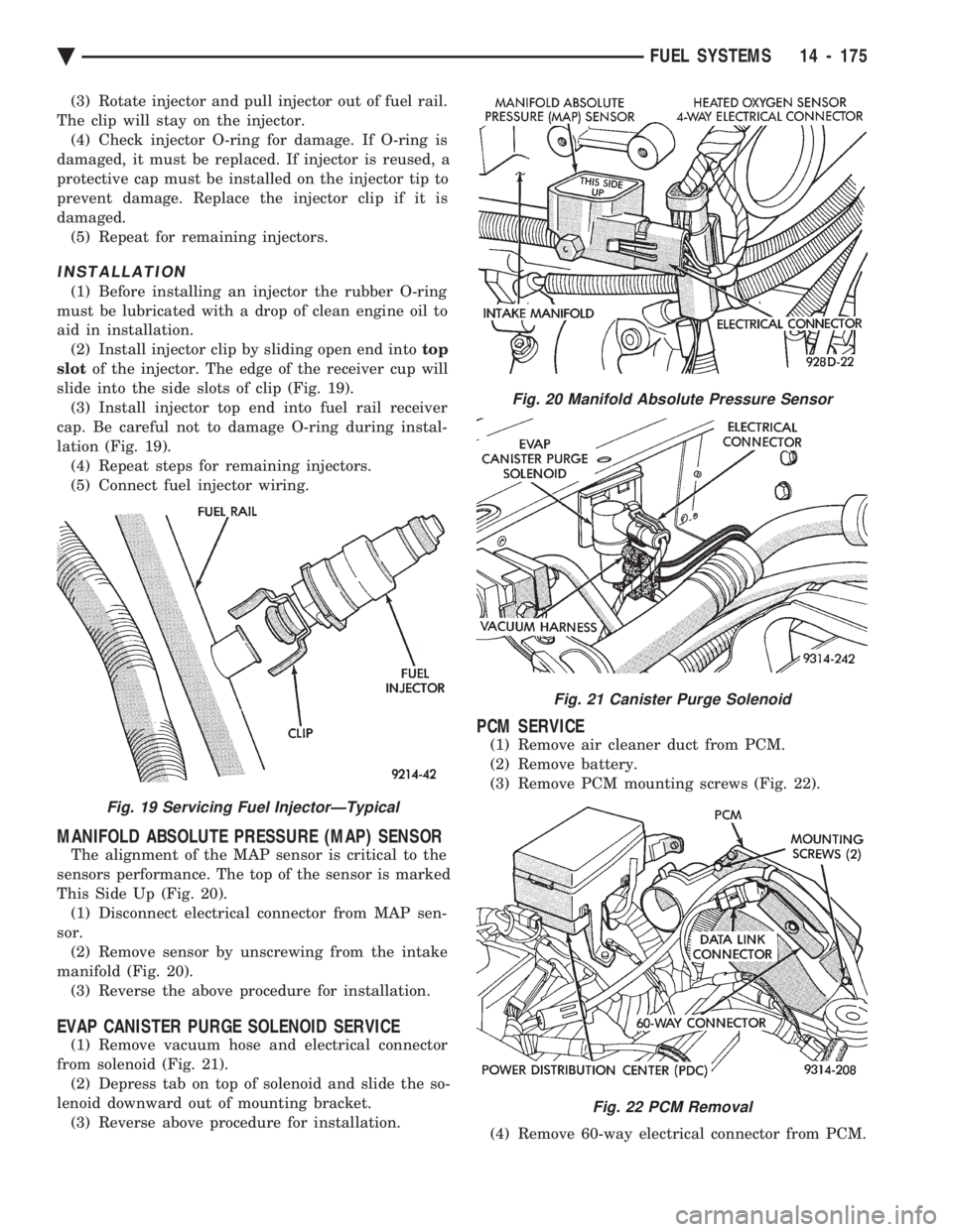
This Side Up (Fig. 20). (1) Disconnect electrical connector from MAP sen-
sor. (2) Remove sensor by unscrewing from the intake
manifold (Fig. 20). (3) Reverse the above procedure for installation.
EVAP CANISTER PURGE SOLENOID SERVICE
(1) Remove vacuum hose and electrical connector
from solenoid (Fig. 21). (2) Depress tab on top of solenoid and slide the so-
lenoid downward out of mounting bracket. (3) Reverse above procedure for installation.
PCM SERVICE
(1) Remove air cleaner duct from PCM.
(2) Remove battery.
(3) Remove PCM mounting screws (Fig. 22).
(4) Remove 60-way electrical connector from PCM.
Fig. 19 Servicing Fuel InjectorÐTypical
Fig. 20 Manifold Absolute Pressure Sensor
Fig. 21 Canister Purge Solenoid
Fig. 22 PCM Removal
Ä FUEL SYSTEMS 14 - 175
Page 2150 of 2438

PRESSURE GAUGES
High quality dial type air pressure gauges are rec-
ommended. After checking pressure with the gauge,
replace valve caps and tighten finger tight.
TIRE INFLATION PRESSURES
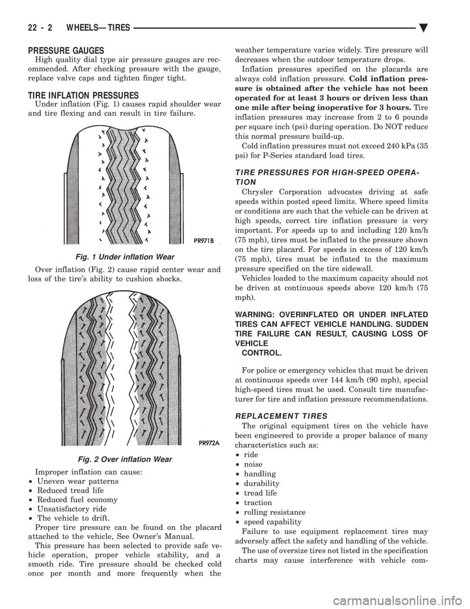
Under inflation (Fig. 1) causes rapid shoulder wear
and tire flexing and can result in tire failure.
Over inflation (Fig. 2) cause rapid center wear and
loss of the tire's ability to cushion shocks.
Improper inflation can cause:
² Uneven wear patterns
² Reduced tread life
² Reduced fuel economy
² Unsatisfactory ride
² The vehicle to drift.
Proper tire pressure can be found on the placard
attached to the vehicle, See Owner's Manual. This pressure has been selected to provide safe ve-
hicle operation, proper vehicle stability, and a
smooth ride. Tire pressure should be checked cold
once per month and more frequently when the weather temperature varies widely. Tire pressure will
decreases when the outdoor temperature drops.
Inflation pressures specified on the placards are
always cold inflation pressure. Cold inflation pres-
sure is obtained after the vehicle has not been
operated for at least 3 hours or driven less than
one mile after being inoperative for 3 hours. Tire
inflation pressures may increase from 2 to 6 pounds
per square inch (psi) during operation. Do NOT reduce
this normal pressure build-up. Cold inflation pressures must not exceed 240 kPa (35
psi) for P-Series standard load tires.
TIRE PRESSURES FOR HIGH-SPEED OPERA- TION
Chrysler Corporation advocates driving at safe
speeds within posted speed limits. Where speed limits
or conditions are such that the vehicle can be driven at
high speeds, correct tire inflation pressure is very
important. For speeds up to and including 120 km/h
(75 mph), tires must be inflated to the pressure shown
on the tire placard. For speeds in excess of 120 km/h
(75 mph), tires must be inflated to the maximum
pressure specified on the tire sidewall. Vehicles loaded to the maximum capacity should not
be driven at continuous speeds above 120 km/h (75
mph).
WARNING: OVERINFLATED OR UNDER INFLATED
TIRES CAN AFFECT VEHICLE HANDLING. SUDDEN
TIRE FAILURE CAN RESULT, CAUSING LOSS OF
VEHICLE CONTROL.
For police or emergency vehicles that must be driven
at continuous speeds over 144 km/h (90 mph), special
high-speed tires must be used. Consult tire manufac-
turer for tire and inflation pressure recommendations.
REPLACEMENT TIRES
The original equipment tires on the vehicle have
been engineered to provide a proper balance of many
characteristics such as:
² ride
² noise
² handling
² durability
² tread life
² traction
² rolling resistance
² speed capability
Failure to use equipment replacement tires may
adversely affect the safety and handling of the vehicle. The use of oversize tires not listed in the specification
charts may cause interference with vehicle com-
Fig. 1 Under inflation Wear
Fig. 2 Over inflation Wear
22 - 2 WHEELSÐTIRES Ä
Page 2402 of 2438

During the cold start warm-up period and the hot
start time delay, the PCM does not energize the so-
lenoid. When de-energized, no vapors are purged.
The PCM de-energizes the solenoid during open loop
operation. The engine enters closed loop operation after it
reaches a specified temperature and the time delay
ends. During closed loop operation, the PCM ener-
gizes and de-energizes the solenoid approximately 5
to 10 times per second, depending upon operating
conditions. The PCM varies the vapor flow rate by
changing solenoid pulse width. Pulse width is the
amount of time the solenoid energizes. The PCM ad-
justs solenoid pulse width based on engine air flow. A rubber boot covers the duty cycle EVAP purge
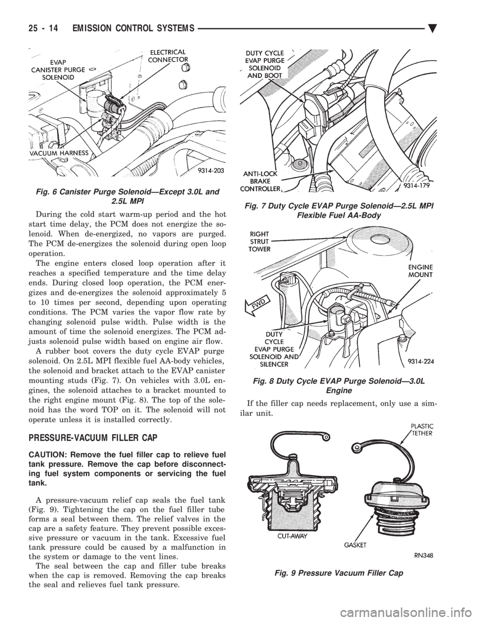
solenoid. On 2.5L MPI flexible fuel AA-body vehicles,
the solenoid and bracket attach to the EVAP canister
mounting studs (Fig. 7). On vehicles with 3.0L en-
gines, the solenoid attaches to a bracket mounted to
the right engine mount (Fig. 8). The top of the sole-
noid has the word TOP on it. The solenoid will not
operate unless it is installed correctly.
PRESSURE-VACUUM FILLER CAP
CAUTION: Remove the fuel filler cap to relieve fuel
tank pressure. Remove the cap before disconnect-
ing fuel system components or servicing the fuel
tank.
A pressure-vacuum relief cap seals the fuel tank
(Fig. 9). Tightening the cap on the fuel filler tube
forms a seal between them. The relief valves in the
cap are a safety feature. They prevent possible exces-
sive pressure or vacuum in the tank. Excessive fuel
tank pressure could be caused by a malfunction in
the system or damage to the vent lines. The seal between the cap and filler tube breaks
when the cap is removed. Removing the cap breaks
the seal and relieves fuel tank pressure. If the filler cap needs replacement, only use a sim-
ilar unit.
Fig. 6 Canister Purge SolenoidÐExcept 3.0L and 2.5L MPI
Fig. 7 Duty Cycle EVAP Purge SolenoidÐ2.5L MPIFlexible Fuel AA-Body
Fig. 8 Duty Cycle EVAP Purge SolenoidÐ3.0L Engine
Fig. 9 Pressure Vacuum Filler Cap
25 - 14 EMISSION CONTROL SYSTEMS Ä