1993 CHEVROLET PLYMOUTH ACCLAIM buttons
[x] Cancel search: buttonsPage 546 of 2438

INSTALLATION (1) Latch switch linkage in the up position.
(2) Insert dimmer shaft into dimmer knob while
aligning switch in to switch pod assembly. (3) Install switch attaching screws.
(4) Unlatch linkage and install onto push buttons.
(5) Operate all switch modes for correct operation.
(6) Install turn signal switch.
(7) Reconnect wiring for turn signal switch, mak-
ing sure wire is properly clipped into position. (8) Place together the inner and outer bezels. In-
stall five inner switch pod panel screws and three
screws from underneath the switch pod. (9) Install turn signal lever by pushing straight
into switch assembly. (10) Install switch pod assembly.
LOWER STEERING COLUMN COVER REMOVAL
(1) Remove screws along top edge of cover.
(2) Remove screw at each lower corner of cover. (3) Remove cover from underneath over column
cover. (4) For installation reverse above procedures.
GLOVEBOX MODULE REMOVAL
(1) Disconnect battery negative cable and isolate
or remove fuse #26 prior to removing switch or wires
may short to ground. (2) Remove cowl side trim panel.
(3) Remove screws at right end of glovebox and
lower corners. (4) Open glovebox, remove light and disconnect
wiring. (5) Remove five screws along top of glovebox frame
and screw at each lower corner. (6) Remove glovebox assembly.
(7) For installation reverse above procedures.
CONCEALED HEADLAMP MODULE REMOVAL
(1) Remove left under panel silencer.
(2) Slide module off bayonet bracket while disen-
gaging spring retainer. (3) Disconnect wiring terminal.
(4) For installation reverse above procedures.
HOOD RELEASE REMOVE
(1) Remove lower column cover.
(2) Remove screws on fuse block and move aside.
(3) Remove screws on hood release assembly to re-
move. (4) For installation reverse above procedures.
AIR CONDITIONING CONTROL REMOVE
(1) Remove center stack bezel.
(2) Remove two control mounting screws (Fig. 28
and 29).
(3) Slide control rearward, disconnect cable, vac-
uum harness, and electrical wiring. With automatic
temperature control, disconnect wiring connector; be-
ing careful not to break off locking tab. (4) For installation reverse above procedures.
Fig. 26 Switch Pod Assembly
Fig. 27 Headlamp Multi-Function Switch
Fig. 28 A/C Control
8E - 54 INSTRUMENT PANEL AND GAUGES Ä
Page 599 of 2438

Remove steering wheel horn pad and disconnect
wire from horn switch. Repeat the above test and if
the test lamp still illuminates, wire is shorted and
should be repaired. If test lamp does not illuminate,
horn switch is defective and must be replaced.
DIAGNOSIS TESTING
Horn does not sound, horn sounds intermittently,
or horn sounds continuously go to Horn Diagnosis
Chart (Fig. 9).
HORN SWITCH REPLACEMENT
WARNING: BEFORE BEGINNING ANY AIR BAG
SYSTEM REMOVAL OR INSTALLATION PROCE-
DURES, REMOVE AND ISOLATE THE NEGATIVE (-)
BATTERY CABLE (GROUND) FROM THE VEHICLE
BATTERY. THIS IS THE ONLY SURE WAY TO DIS-
ABLE THE AIR BAG SYSTEM. FAILURE TO DO
THIS COULD RESULT IN ACCIDENTAL AIR BAG
DEPLOYMENT AND POSSIBLE PERSONAL INJURY. (1) Disconnect and isolate negative battery cable
in engine compartment. (2) Remove four retaining nuts from back of steer-
ing wheel. Remove air bag module (Fig. 10 and 11). (a) Disconnect wire from rear of air bag module.
(b) Place air bag module on a clean level surface
with pad facing upward.
(3) Remove horn switch assembly from steering
wheel. (a) On luxury steering wheel (Fig. 10), pry out
two trim cover buttons on back of steering wheel to
access retaining screws for the horn switch. The
sport steering wheel (Fig. 11) the horn screws are
accessible after the Air Bag is removed. (b) Remove two screws and disconnect horn wires
located in the lower portion of steering wheel. Feed
wires through the access ports and remove horn
switch.
(4) For installation reverse the above procedures.
Use caution not to pinch wires.
Fig. 8 Testing Horn for Continuous SoundÐ AP and AA Bodies
Fig. 7 Testing for Short to GroundÐAC and AY Bodies
Ä HORNS 8G - 3
Page 603 of 2438

VEHICLE SPEED CONTROL
CONTENTS
page page
CHECKING FOR FAULT CODE .............. 3
DIAGNOSIS PROCEDURES ................ 2
GENERAL INFORMATION .................. 1
INOPERATIVE SYSTEM ................... 3
POWERTRAIN CONTROL MODULE ELECTRICAL TEST ................................ 5
ROAD TEST ............................ 2
SERVO ELECTRICAL TESTS ............... 4
SERVO UNIT ............................ 9 SERVO VACUUM TEST
................... 9
STOP LAMP VEHICLE SPEED CONTROL SWITCH TEST ......................... 8
VACUUM SUPPLY TEST .................. 9
VEHICLE SPEED CONTROL SWITCH REMOVAL ........................... 10
VEHICLE SPEED CONTROL SWITCH TEST . . . 8
VEHICLE SPEED CONTROL ELECTRICAL TESTS ............................... 3
GENERAL INFORMATION
The vehicle speed control is electronically con-
trolled and vacuum operated. The electronic control
is integrated into the powertrain control module, lo-
cated next to battery. The controls are located on the
steering wheel and consist of the ON/OFF, RESUME/
ACCEL and SET/DECEL buttons (Fig. 1). For iden-
tification and location of the major components (Fig.
2 through 8).
The system is designed to operate at speeds above
35 mph (50 km/h).
WARNING: THE USE OF VEHICLE SPEED CON-
TROL IS NOT RECOMMENDED WHEN DRIVING
CONDITIONS DO NOT PERMIT MAINTAINING A
CONSTANT SPEED, SUCH AS IN HEAVY TRAFFIC
OR ON ROADS THAT ARE WINDING, ICY, SNOW
COVERED, OR SLIPPERY.
TO ACTIVATE: The ON/OFF button to the de-
pressed latched position, ON, the vehicle speed con-
trol function is now ready for use. TO DEACTIVATE:
A soft tap of the brake pedal,
normal brake application or depressing the clutch
pedal while the system is engaged will disengage ve-
hicle speed control without erasing memory. A sud-
den increase in engine rpm may be experienced if the
clutch pedal is depressed while the vehicle speed con-
trol is engaged. Pushing the ON/OFF button to the
unlatched position or turning off the ignition erases
the memory. TO SET SPEED: When the vehicle has reached
the desired speed push the SET/DECEL button to en-
gage system which will then automatically maintain
the desired speed. TO DECELERATE: When vehicle speed control is
engaged, holding the SET/DECEL button depressed
allows the vehicle to coast to a lower speed setting.
Fig. 1 Vehicle Speed Control Switch
Fig. 2 Vehicle Speed ControlÐ2.2L and 2.5L
Ä VEHICLE SPEED CONTROL 8H - 1
Page 635 of 2438

WIPER SWITCH SERVICE PROCEDURE
WARNING: ON VEHICLES EQUIPPED WITH AIR-
BAG, SEE GROUP 8M, RESTRAINT SYSTEMS FOR
STEERING WHEEL OR COLUMN REMOVAL PROCE-
DURES.
AC AND AY BODIES
The wiper switch is part of the multi-function
switch assembly. If the wiper switch fails, the multi-
function switch must be replaced. Refer to Group 8J,
Turn Signals and Hazard Warning Flasher for multi-
function switch service procedure.
AG AND AJ BODIES
REMOVAL
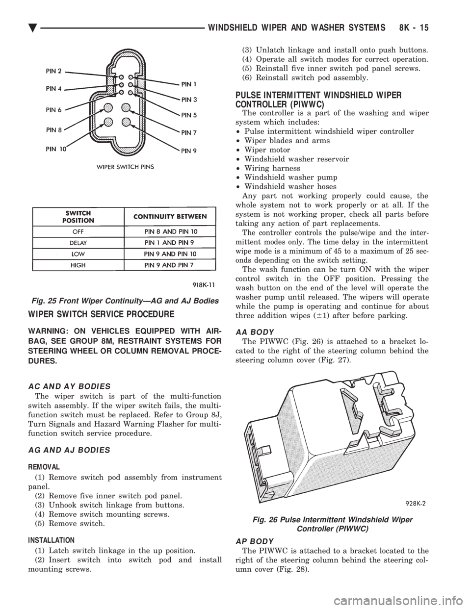
(1) Remove switch pod assembly from instrument
panel. (2) Remove five inner switch pod panel.
(3) Unhook switch linkage from buttons.
(4) Remove switch mounting screws.
(5) Remove switch.
INSTALLATION (1) Latch switch linkage in the up position.
(2) Insert switch into switch pod and install
mounting screws. (3) Unlatch linkage and install onto push buttons.
(4) Operate all switch modes for correct operation.
(5) Reinstall five inner switch pod panel screws.
(6) Reinstall switch pod assembly.
PULSE INTERMITTENT WINDSHIELD WIPER
CONTROLLER (PIWWC)
The controller is a part of the washing and wiper
system which includes:
² Pulse intermittent windshield wiper controller
² Wiper blades and arms
² Wiper motor
² Windshield washer reservoir
² Wiring harness
² Windshield washer pump
² Windshield washer hoses
Any part not working properly could cause, the
whole system not to work properly or at all. If the
system is not working proper, check all parts before
taking any action of part replacements.
The controller controls the pulse/wipe and the inter-
mittent modes only. The time delay in the intermittent
wipe mode is a minimum of 45 to a maximum of 25 sec-
onds depending on the switch setting.
The wash function can be turn ON with the wiper
control switch in the OFF position. Pressing the
wash button on the end of the level will operate the
washer pump until released. The wipers will operate
while the pump is operating and continue for about
three addition wipes ( 61) after before parking.
AA BODY
The PIWWC (Fig. 26) is attached to a bracket lo-
cated to the right of the steering column behind the
steering column cover (Fig. 27).
AP BODY
The PIWWC is attached to a bracket located to the
right of the steering column behind the steering col-
umn cover (Fig. 28).
Fig. 25 Front Wiper ContinuityÐAG and AJ Bodies
Fig. 26 Pulse Intermittent Windshield Wiper Controller (PIWWC)
Ä WINDSHIELD WIPER AND WASHER SYSTEMS 8K - 15
Page 699 of 2438

to the deck lid open position. If the pull down limit
switch is depressed at this time, the motor should
stop.(c) If these results are not obtained, replace the
pull down motor assembly.
REMOTE KEYLESS ENTRY
OPERATION
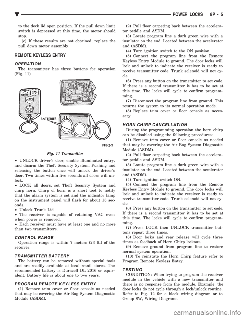
The transmitter has three buttons for operation
(Fig. 11).
² UNLOCK driver's door, enable illuminated entry,
and disarm the Theft Security System. Pushing and
releasing the button once will unlock the driver's
door. Two times within five seconds all doors will un-
lock.
² LOCK all doors, set Theft Security System and
chirp horn. Chirp of horn is a short toot to notify
that the alarm system is set and the indicator lamp
on the instrument panel will flash for about 15 sec-
onds.
² Unlock Trunk Lid
² The receiver is capable of retaining VAC even
when power is removed.
² Each receiver must have at least one and no more
than two transmitters.
CONTROL RANGE
Operation range is within 7 meters (23 ft.) of the
receiver.
TRANSMITTER BATTERY
The battery can be removed without special tools
and are readily available at local retail stores. The
recommended battery is Duracell DL 2016 or equiv-
alent. Battery life is about one to two years.
PROGRAM REMOTE KEYLESS ENTRY
(1) Remove trim cover or floor console as needed
that may be covering the Air Bag System Diagnostic
Module (ASDM). (2) Pull floor carpeting back between the accelera-
tor peddle and ASDM. (3) Locate program line a dark green wire with a
insulator on the end. Located between the accelerator
and (ASDM). (4) Turn ignition switch to the ON position.
(5) Connect the program line from the Remote
Keyless Entry Module to ground. The door locks will
lock and unlock to indicate the receiver is ready to
receive transmitter code. Trunk solenoid will not cy-
cle. (6) Press any button on the transmitter to set code.
If there is a second transmitter it has to be set at
this time. The locks will cycle to confirm program-
ming. (7) Disconnect the program line from ground. This
returns the system to its normal operation mode. (8) Replace trim cover or floor console as neces-
sary.
HORN CHIRP CANCELLATION
During the programming operation the horn chirp
can be disabled using the following procedures: (1) Remove trim cover or floor console as needed
that may be covering the Air Bag System Diagnostic
Module (ASDM). (2) Pull floor carpeting back between the accelera-
tor peddle and ASDM. (3) Locate program line a dark green wire with a
insulator on the end. Located between the accelerator
and (ASDM). (4) Turn ignition switch ON.
(5) Connect the program line from the Remote
Keyless Entry Module to ground. The door locks will
lock and unlock to indicate the receiver is ready to
receive transmitter code. Trunk solenoid will not cy-
cle. (6) Press any button on the transmitter to set code.
If there is a second transmitter it has to be set at
this time. The locks will cycle to confirm program-
ming. (7) Press LOCK then UNLOCK transmitter but-
tons repeat three times. (8) Door locks and rear release will cycle three
times as feedback of Horn Chirp lockout. (9) Remove ground from program line to restore
normal system operation. (10) To reinstate the Horn Chirp feature refer to
Program Remote Keyless Entry.
TESTING
CONDITION: When trying to program the receiver
module in the vehicle with a new transmitter and
there is no response from the module, Example: the
door locks do not cycle through a lock/unlock routine.
Refer to Fig. 12 for a block wiring diagram or to
Group 8W, Wiring Diagrams.
Fig. 11 Transmitter
Ä POWER LOCKS 8P - 5
Page 712 of 2438

SYSTEM SOFT LIMITS
This portion of the system becomes activated when
the control module must shut off a specific seat, re-
cliner or mirror motor because it has reached the end
of its travel. When a mechanical stall condition is de-
tected, the control module will set a soft limit in its
memory and will not allow the motor to be driven
past that point. To override the soft limits, activate the seat or re-
cliner switch twice in the desired direction holding
the switch activated until the end of travel has been
reached. Reactivate and hold the switch once more
for three seconds. This will cause new soft limits to
be set in the control module.
SETTING SYSTEM SOFT LIMITS
If the control module or motor assemblies have
been replaced, the control module must learn its new
soft limits. To do this, perform the memory seat di-
agnostic self-test. After the tests are completed, the
control module will have learned and memorized its
new soft limits.
TEST PROCEDURES
Before any testing is attempted, the battery should
be carefully charged and all connections and termi-
nals cleaned and tightened to insure proper continu-
ity and grounds.
MEMORY SEAT AND MIRROR DIAGNOSTIC
SELF-TESTS
The system has a built-in set of three self-tests
which check all components in the system while giv-
ing a visual feedback. To enter the first self-test mode, switch test, press
memory position 1 and 2 buttons, hold for at least
five seconds and no longer than ten seconds. Follow
this immediately by pressing the Set button and hold
for at least five seconds but less than ten seconds.
Three seconds after the button is released, the seat,
recliner and mirrors will move to a mid-travel posi-
tion. Within ten seconds, press and release a seat
button to activate a seat or recliner motor. All
switches except the mirror switches may now be
tested one at a time. The memory switches, Position
1 and 2 and Set buttons, may also be tested. A good
switch contact actuation will NOD the seat. The seat
nod consists of seat front up and seat track forward
followed by seat front down and seat track rearward.
The nod also includes both outside power rear view
mirrors operating in the vertical plane. The system
will continue NODDING for good switches until 10
seconds pass without any switch actuation. Within 10 seconds of the last seat nod, press mem-
ory position 1 and 2 buttons for at least 5 seconds
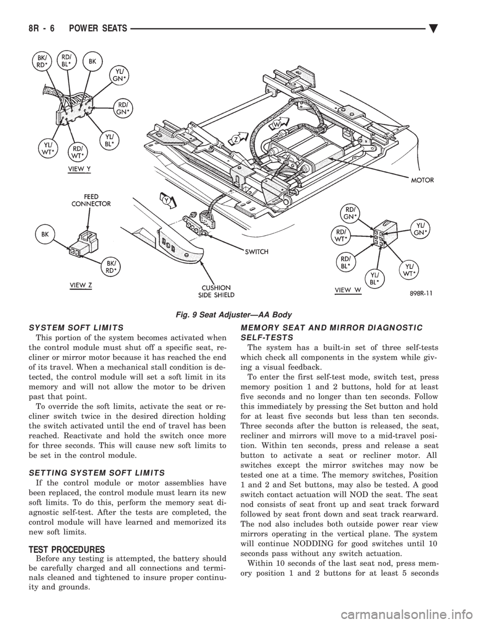
Fig. 9 Seat AdjusterÐAA Body
8R - 6 POWER SEATS Ä
Page 714 of 2438

but less than 10 seconds, and then release. The seat
will move, after 3 seconds, to a full down and rear-
ward position. This is the seat check mode. The control module
will now move the motors to a stall in forward, rear-
ward, front up, front down, rear up, rear down, re-
cliner forward, and recliner rear ward positions. If a
problem exists, the control module will not move that
part of the seat. After all motors have been run to
stall, the system will pause for 3 seconds, then re-
turn to the mid-travel position. The control module will now move the seat through
its positions for two seconds run time. If a problem has been found, the control module
will go into a loop and just move the problem part of
the system. To exit the loop, press the Set or Position
1 or 2 buttons or repair the fault; i.e.: repair a ter-
minal push out, etc. When the seat movements are complete, the sys-
tem will return to its normal operating mode unless
memory Position 1 and 2 buttons are held for at least
five seconds, but less than ten seconds and then re-
leased. The seat will return to its mid-travel position
and the mirrors will move full downward and to the
left. This is the mirror check mode. The control mod-
ule will then move the right mirror fully horizontal
outboard, and horizontal inboard. This is followed by
the left mirror fully horizontal inboard, horizontal
out board, vertical up, and vertical down. Each motor
will be driven until the associated mirror plane face
has been stalled for up to 1-1/2 seconds at each end
of travel. If the control module encounters a problem
with any position sensing rheostat that is connected
to each motor, that particular motor will not be ac-
tuated. After an other three second pause, the control
module will again try running the mirror motors in
the directions given above plus the right mirror ver-
tical up and vertical down. Any motor that has no
problem will run for two seconds in each of the given
directions. If a problem is found, the control module will go
into a loop and move only the problem part of the
system. To exit the loop, repair the fault, or press the
Set, Position 1 or 2 buttons. The control module will
then finish the motor actuation that are shown
Fig. 13 Seat Wing Switch Continuity
Fig. 14 Lumbar Switch Continuity
Fig. 15 Memory Seat Switch
8R - 8 POWER SEATS Ä
Page 737 of 2438

POWER MIRRORS
CONTENTS
page page
AUTOMATIC DAY/NIGHT INSIDE MIRROR .... 7
AUTOMATIC DAY/NIGHT INSIDE MIRROR WITH ULTRALIGHT HEADLAMP CONTROL ....... 7
GENERAL INFORMATION .................. 1
HEATED MIRROR ........................ 2
INSIDE MIRROR/READING LAMPS BULB/LENS REPLACEMENT ........................ 6
INSIDE MIRROR/READING LAMPS REPLACEMENT ........................ 6
MIRROR ASSEMBLY REPLACEMENTÐAA BODY.5
MIRROR ASSEMBLY REPLACEMENTÐ AC AND AY BODIES .................... 5
MIRROR ASSEMBLY REPLACEMENTÐAG BODY.5
MIRROR ASSEMBLY REPLACEMENTÐAJ BODY.5
MIRROR ASSEMBLY REPLACEMENTÐAP BODY.5
MIRROR MOTOR TEST PROCEDURE ........ 2
MIRROR SWITCH REPLACEMENTÐAA BODY . 3
MIRROR SWITCH REPLACEMENTÐAC AND AY BODIES .............................. 4
MIRROR SWITCH REPLACEMENTÐAG AND AJ BODIES .............................. 3
MIRROR SWITCH REPLACEMENTÐAP BODY . 4
MIRROR SWITCH TEST PROCEDURE ....... 2
TEST PROCEDURES ...................... 2
GENERAL INFORMATION
Electrically operated power mirrors are available
on all car lines. The mirrors are controlled by a sin-
gle switch assembly located either on the driver's
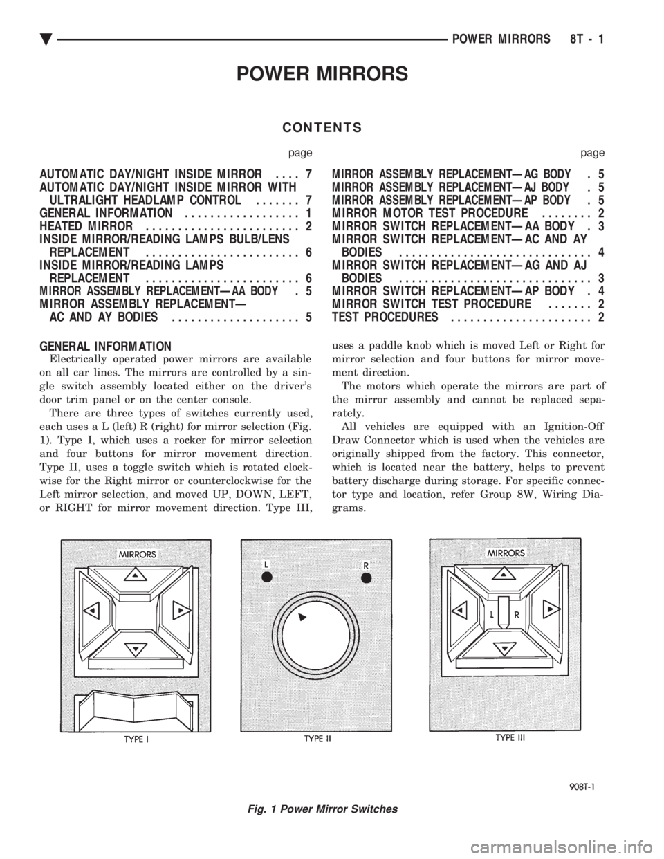
door trim panel or on the center console. There are three types of switches currently used,
each use s a L (left) R (right) for mirror selection (Fig.
1). Type I, which uses a rocker for mirror selection
and four buttons for mirror movement direction.
Type II, uses a toggle switch which is rotated clock-
wise for the Right mirror or counterclockwise for the
Left mirror selection, and moved UP, DOWN, LEFT,
or RIGHT for mirror movement direction. Type III, uses a paddle knob which is moved Left or Right for
mirror selection and four buttons for mirror move-
ment direction.
The motors which operate the mirrors are part of
the mirror assembly and cannot be replaced sepa-
rately. All vehicles are equipped with an Ignition-Off
Draw Connector which is used when the vehicles are
originally shipped from the factory. This connector,
which is located near the battery, helps to prevent
battery discharge during storage. For specific connec-
tor type and location, refer Group 8W, Wiring Dia-
grams.
Fig. 1 Power Mirror Switches
Ä POWER MIRRORS 8T - 1