1993 CHEVROLET PLYMOUTH ACCLAIM Wheel bearing
[x] Cancel search: Wheel bearingPage 116 of 2438
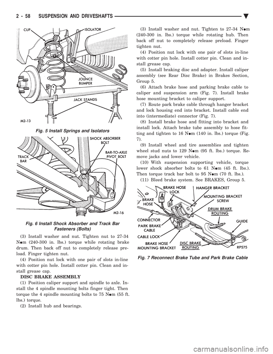
(3) Install washer and nut. Tighten nut to 27-34
N Im (240-300 in. lbs.) torque while rotating brake
drum. Then back off nut to completely release pre-
load. Finger tighten nut. (4) Position nut lock with one pair of slots in-line
with cotter pin hole. Install cotter pin. Clean and in-
stall grease cap. DISC BRAKE ASSEMBLY
(1) Position caliper support and spindle to axle. In-
stall the 4 spindle mounting bolts finger tight. Then
torque the 4 spindle mounting bolts to 75 N Im (55 ft.
lbs.) torque. (2) Install hub and bearings. (3) Install washer and nut. Tighten to 27-34 N
Im
(240-300 in. lbs.) torque while rotating hub. Then
back off nut to completely release preload. Finger
tighten nut. (4) Position nut lock with one pair of slots in-line
with cotter pin hole. Install cotter pin. Clean and in-
stall grease cap. (5) Install braking disc and adapter. Install caliper
assembly (see Rear Disc Brake) in Brakes Section,
Group 5. (6) Attach brake hose and parking brake cable to
caliper and suspension arm (Fig. 7). Install brake
hose mounting bracket to caliper support. (7) Route park brake cable through hanger bracket
and lock housing end into bracket. Install cable end
into (intermediate) connector (Fig. 7). (8) Install brake hose and fitting into bracket and
install lock. Attach brake tube assembly to hose fit-
ting and tighten to 16 N Im (140 in. lbs.) torque (Fig.
7). (9) Install wheel and tire assemblies and tighten
wheel stud nuts to 129 N Im (95 ft. lbs.) torque. Re-
move jacks and lower vehicle. (10) With suspension supporting vehicle, torque
lower shock absorber bolts to 61 N Im (45 ft. lbs.).
Then torque track bar bolt to 95 N Im (70 ft. lbs.).
(11) Bleed brake system. See BRAKES, Group 5.
Fig. 5 Install Springs and Isolators
Fig. 6 Install Shock Absorber and Track Bar Fasteners (Bolts)
Fig. 7 Reconnect Brake Tube and Park Brake Cable
2 - 58 SUSPENSION AND DRIVESHAFTS Ä
Page 145 of 2438

INSTALL
(1) Inspect O-Ring condition and position on sole-
noid stem. (O-Ring can become dislodged during re-
moval (Fig. 16). (2) Install solenoid with tangs to top ledge of hous-
ing and install retaining clip. (3) Reconnect air line and electrical connection.
STRUT (AIR SUSPENSION) DAMPERASSEMBLY
Service procedures for removal and installation for
(air or steel spring) assemblies are essentially the
same. Except for air venting/recharging and discon-
necting/connecting air lines and electrical connection.
REMOVAL (1) Disconnect battery negative cable.
(2) Hoist vehicle and remove wheel and tire assem-
bly. (3) See AIR LINES AND FITTINGS and discon-
nect air line. (4) Disconnect electrical leads, solenoid and height
sensors. (5) See SOLENOIDS (STRUT AND AIR SPRING)
and vent air spring and remove solenoids. (6) See STRUT DAMPER ASSEMBLY in FRONT
SUSPENSION and remove strut.
DISASSEMBLY/ASSEMBLE Disassembly is restricted to upper mount and bear-
ing housing. The strut shock absorber, air spring
with integral height sensor, solenoid and wiring har-
ness are serviced as an assembly. (1) Hold retaining plate locking washer and re-
move strut rod nut. (2) Remove locking washer, retainer plate, spacer,
flat washer and mount/bearing housing assembly
(Fig. 17). (3) Assemble in reverse order. Hold retainer plate
locking washer with suitable tool and tighten strut
rod nut to 75 N Im (55 ft. lbs.) torque.
INSTALLATION (1) See STRUT DAMPER ASSEMBLY in FRONT
SUSPENSION and install strut. (2) Install solenoid, see: SOLENOIDS (STRUT
AND AIR SPRINGS). (3) Connect electrical leads, solenoid and height
sensor. (4) Charge (inflate) air spring. See RECHARGE-
AIR SPRING to activate spring solenoid and air com-
pressor. Add air for 60 seconds.
RECHARGE AIR SPRING
To activate compressor; Ground Pin S08 to Pin
X20. To Activate Spring Solenoid:
² LF: Ground Pin S31 to X20 ²
RF: Ground Pin S30 to X20
² RR: Ground Pin S32 to X20
AIR SPRINGS REAR
REMOVAL
(1) Disconnect battery negative cable, hoist vehicle
and remove wheel and tire assembly. (2) See AIR LINES AND FITTINGS and discon-
nect air line and electrical connector from solenoid. (3) See SOLENOIDS (STRUT AND AIR SPRINGS)
and vent air from spring. Remove solenoid. (4) Release upper air spring alignment/retainer
clips. (Fig. 18) (5) Remove lower spring to axle nut (Fig. 19).
(6) Pry assembly down to pull alignment studs
through retaining clips (Fig. 20). Remove assembly.
INSTALLATION
(1) Position assembly lower stud into axle seat and
upper alignment pins through frame rail adaptor. (2) Install upper retaining clips.
(3) Install lower spring to axle nut: LOOSE AS-
SEMBLE. (4) Install solenoid and connect air line and electri-
cal connector. (5) Charge (inflate) air spring. See RECHARGING
AIR SPRING and add air for 60 seconds. (6) AFTER partial air recharge tighten lower nut
Fig. 17 Air Strut Upper Mount Assembly
Ä SUSPENSION AND DRIVESHAFTS 2 - 87
Page 148 of 2438
² AC, AY Bodies 108 N Im (80 ft. lbs.)
(12) Install brake drum (Fig. 1).
(13) Install washer and nut. Tighten adjusting nut
to 27-34 N Im (240-300 in. lbs.) torque while rotating
wheel. Back off adjusting nut with wrench to com-
pletely release bearing preload. Finger tighten ad-
justing nut. (14) Position nut lock with one pair of slots in-line
with cotter pin hole. Install cotter pin. The end play
should be 0.025-0.076 mm (0.001-0.003 inch). Clean
and install grease cap. (15) Install wheel and tire assembly. Tighten
wheel nut to 129 N Im (95 ft. lbs.) torque.
(16) Lower vehicle.
(17) Check alignment specifications.
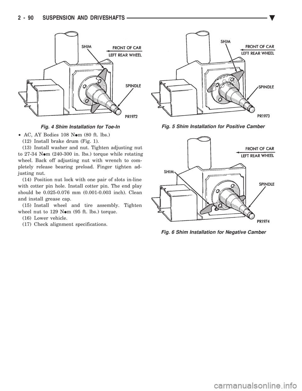
Fig. 4 Shim Installation for Toe-InFig. 5 Shim Installation for Positive Camber
Fig. 6 Shim Installation for Negative Camber
2 - 90 SUSPENSION AND DRIVESHAFTS Ä
Page 151 of 2438

BRAKES
CONTENTS
page page
ANTI-LOCK BRAKE SYSTEMÐBENDIX ANTI-LOCK 10 AC/Y BODY ............. 72
ANTI-LOCK BRAKE SYSTEMÐBENDIX ANTI-LOCK 6 AA,AG,AJ,AP BODY ....... 113
BRAKE DISC (ROTOR) ................... 53
BRAKE SUPPORT ASSEMBLY ............. 25
FRONT DISC BRAKES ................... 31
GENERAL INFORMATION .................. 1
HYDRAULIC SYSTEM CONTROL VALVES . . . 26
KELSEY HAYES DOUBLE PIN FAMILY CALIPER ............................ 35 KELSEY HAYES DOUBLE PIN NON-FAMILY
CALIPER ............................ 38
MASTER CYLINDER ..................... 66
PARKING BRAKES ...................... 57
POWER BRAKES ....................... 68
REAR DISC BRAKES .................... 45
REAR WHEEL DRUM BRAKES ............ 18
SERVICE ADJUSTMENTS .................. 4
WHEEL BEARINGS ...................... 70
WHEEL CYLINDERS ..................... 23
GENERAL INFORMATION
Throughout this group, references may be made to
a particular vehicle by letter or number designation.
A chart showing the break down of these designa-
tions is included in the Introduction Section at the
front of this service manual. Standard brake equipment consists of:
² Double pin floating caliper disc front brakes.
² Rear automatic adjusting drum brakes.
² Differential valve with a brake warning switch.
² Master cylinder.
² Vacuum power booster.
² Double pin floating caliper rear disc brakes are
available on some models. The Bendix Anti-Lock 10 braking system, uses the
standard power brake system caliper assemblies,
braking discs, pedal assembly, brake lines and hoses.
The unique parts of the Bendix Anti-Lock 10 braking
system consists of the following components. Propor-
tioning valves, wheel speed sensors, tone wheels,
electronic control unit, modulator assembly and hy-
draulic assembly. These components replace the con-
ventional master cylinder and power booster. The
components will be described in detail in the Bendix
Anti-Lock 10 brake section in this group of the ser-
vice manual. The Bendix Anti-Lock 6 braking system, uses the
following standard brake system components. Master
cylinder, power booster, caliper assemblies, braking
discs, pedal assembly, brake lines and hoses. The
unique parts of the Bendix Anti-Lock 6 braking sys-
tem consists of the following components. Modulator
assembly, unique proportioning valves, wheel speed
sensors, tone wheels, and electronic control unit.
These components will be described in detail in the
Bendix Anti-Lock 6 brake section in this group of the
service manual. The front disc brake shoes have semi-metallic lin-
ings. The hydraulic brake system (Fig .123and4)is
diagonally split on both the Non-ABS and ABS brak-
ing system. With the left front and right rear brakes
on one hydraulic system and the right front and left
rear on the other. The Non-ABS and ABS brake system may use dif-
ferent types of brake line fittings and tubing flares.
The Non-ABS brake system uses double wall tubing
flares and fittings at all tubing joint locations. Some
ABS brake systems use both ISO style tubing flares
and double wall tubing flares and corresponding fit-
tings at different joint locations. See (Figs . 2 3 and 4)
for specific joint locations and type of tubing flare. The front disc brakes consist of two different types
of caliper assemblies. A double pin Kelsey-Hayes cal-
iper (family caliper) with a bolt-on adapter attached
to the steering knuckle. Or a double pin Kelsey-
Hayes caliper (non-family caliper) which mounts di-
rectly to rails on the steering knuckle. The non-
family caliper is only used on the AY Body
(Imperials).
CAUTION: Caliper pistons, boots and seals for the
different caliper assemblies used on the front and
rear disc brake assemblies are not interchangeable.
Misusage could result in a complete brake system
failure. Be sure that the parts are replaced with the
correct replacement parts, refer to the parts book
for the type and model year of the vehicle being
worked on.
The master cylinder is anodized, lightweight alu-
minum, with a bore size of 24.0mm, 21.0mm or 7/8
inch.
Ä BRAKES 5 - 1
Page 168 of 2438
REAR WHEEL DRUM BRAKES INDEX
page page
Brake Drum Refacing ..................... 21
Brake Shoe Assemblies ................... 19 Description
............................. 18
Service Procedures ....................... 18
DESCRIPTION
Rear wheel drum brakes (Fig .2&3)aretwoshoe,
internal expanding type with an automatic adjuster
screw assembly that is activated each time the
brakes are applied. The automatic adjuster screw is
located directly below the wheel cylinder as shown in
figure (Fig .2&3).
WARNING: DUST AND DIRT ON BRAKE PARTS
GENERATED DURING THE NORMAL USE AND
WEAR OF MOTOR VEHICLE BRAKE SYSTEMS MAY
CONTAIN ASBESTOS FIBERS. BREATHING EXCES-
SIVE CONCENTRATIONS OF ASBESTOS FIBERS
CAN CAUSE SERIOUS BODILY HARM, SUCH AS
ASBESTOSIS AND CANCER. EXTREME CARE
SHOULD BE EXERCISED WHILE SERVICING
BRAKE ASSEMBLIES OR COMPONENTS. DO NOT CLEAN BRAKE ASSEMBLIES OR COM-
PONENTS WITH COMPRESSED AIR OR BY DRY
BRUSHING; USE A VACUUM CLEANER SPECIFI-
CALLY RECOMMENDED FOR USE WITH ASBES-
TOS FIBERS. IF A SUITABLE VACUUM CLEANER IS
NOT AVAILABLE, CLEANING SHOULD BE DONE
WET USING A WATER DAMPENED CLOTH. DO NOT CREATE DUST BY SANDING, GRINDING,
AND/OR SHAVING BRAKE LININGS OR PADS UN-
LESS SUCH OPERATION IS DONE WHILE USING
PROPERLY EXHAUST VENTILATED EQUIPMENT. DISPOSE OF ALL DUST AND DIRT SUSPECTED
TO CONTAIN ANY ASBESTOS FIBERS IN SEALED
BAGS OR CONTAINERS TO MINIMIZE DUST EXPO-
SURE TO YOURSELF AND OTHERS. FOLLOW ALL RECOMMENDED PRACTICES PRE-
SCRIBED BY THE OCCUPATIONAL SAFETY AND
HEALTH ADMINISTRATION AND THE ENVIRON-
MENTAL PROTECTION AGENCY. FOR THE HAN-
DLING, PROCESSING, AND DISPOSITION OF DUST
OR DIRT WHICH MAY CONTAIN ASBESTOS FI-
BERS. IT IS RECOMMENDED NOT TO BREATH ANY
TYPE OF BRAKE LINING MATERIAL DUST EVEN
ASBESTOS FREE, DUE TO THE FIBROUS NATURE
OF THE MATERIALS BEING USED.
SERVICE PROCEDURES
REAR BRAKE DRUM REMOVAL
If the rear brake drum is difficult to remove, fur-
ther clearance can be obtained by backing off the
brake automatic adjuster screw. Remove rubber plug
from the top of the support plate and rotate the au-
tomatic adjuster screw assembly with an upward mo-
tion, using the Brake Adjuster, Special Tool C-3784. See adjusting rear service brakes in the Service
Adjustments section in this group of the service man-
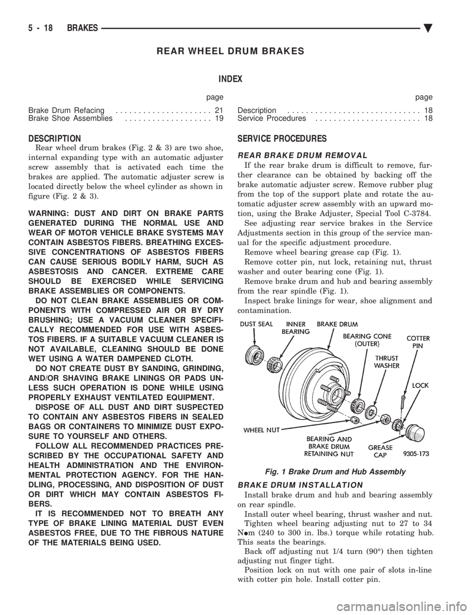
ual for the specific adjustment procedure. Remove wheel bearing grease cap (Fig. 1).
Remove cotter pin, nut lock, retaining nut, thrust
washer and outer bearing cone (Fig. 1). Remove brake drum and hub and bearing assembly
from the rear spindle (Fig. 1). Inspect brake linings for wear, shoe alignment and
contamination.
BRAKE DRUM INSTALLATION
Install brake drum and hub and bearing assembly
on rear spindle. Install outer wheel bearing, thrust washer and nut.
Tighten wheel bearing adjusting nut to 27 to 34
N Im (240 to 300 in. lbs.) torque while rotating hub.
This seats the bearings. Back off adjusting nut 1/4 turn (90É) then tighten
adjusting nut finger tight. Position lock on nut with one pair of slots in-line
with cotter pin hole. Install cotter pin.
Fig. 1 Brake Drum and Hub Assembly
5 - 18 BRAKES Ä
Page 172 of 2438
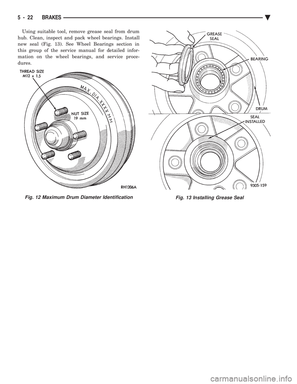
Using suitable tool, remove grease seal from drum
hub. Clean, inspect and pack wheel bearings. Install
new seal (Fig. 13). See Wheel Bearings section in
this group of the service manual for detailed infor-
mation on the wheel bearings, and service proce-
dures.
Fig. 12 Maximum Drum Diameter IdentificationFig. 13 Installing Grease Seal
5 - 22 BRAKES Ä
Page 213 of 2438
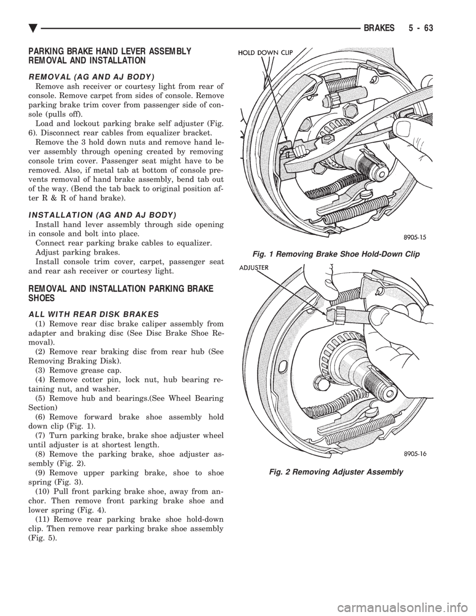
PARKING BRAKE HAND LEVER ASSEMBLY
REMOVAL AND INSTALLATION
REMOVAL (AG AND AJ BODY)
Remove ash receiver or courtesy light from rear of
console. Remove carpet from sides of console. Remove
parking brake trim cover from passenger side of con-
sole (pulls off). Load and lockout parking brake self adjuster (Fig.
6). Disconnect rear cables from equalizer bracket. Remove the 3 hold down nuts and remove hand le-
ver assembly through opening created by removing
console trim cover. Passenger seat might have to be
removed. Also, if metal tab at bottom of console pre-
vents removal of hand brake assembly, bend tab out
of the way. (Bend the tab back to original position af-
terR&Rof hand brake).
INSTALLATION (AG AND AJ BODY)
Install hand lever assembly through side opening
in console and bolt into place. Connect rear parking brake cables to equalizer.
Adjust parking brakes.
Install console trim cover, carpet, passenger seat
and rear ash receiver or courtesy light.
REMOVAL AND INSTALLATION PARKING BRAKE
SHOES
ALL WITH REAR DISK BRAKES
(1) Remove rear disc brake caliper assembly from
adapter and braking disc (See Disc Brake Shoe Re-
moval). (2) Remove rear braking disc from rear hub (See
Removing Braking Disk). (3) Remove grease cap.
(4) Remove cotter pin, lock nut, hub bearing re-
taining nut, and washer. (5) Remove hub and bearings.(See Wheel Bearing
Section) (6) Remove forward brake shoe assembly hold
down clip (Fig. 1). (7) Turn parking brake, brake shoe adjuster wheel
until adjuster is at shortest length. (8) Remove the parking brake, shoe adjuster as-
sembly (Fig. 2). (9) Remove upper parking brake, shoe to shoe
spring (Fig. 3). (10) Pull front parking brake shoe, away from an-
chor. Then remove front parking brake shoe and
lower spring (Fig. 4). (11) Remove rear parking brake shoe hold-down
clip. Then remove rear parking brake shoe assembly
(Fig. 5).
Fig. 1 Removing Brake Shoe Hold-Down Clip
Fig. 2 Removing Adjuster Assembly
Ä BRAKES 5 - 63
Page 214 of 2438

INSTALLING PARKING BRAKE SHOES
(1) Install rear parking brake shoe and holddown
clip (Fig. 6). (2) Install lower parking brake, shoe to shoe re-
turn spring (Fig. 7). (3) Pull forward parking brake shoe over anchor
block until properly located on adapter. (4) Install upper parking brake, shoe to shoe re-
turn spring (Fig. 8). (5) Install parking brake shoe adjuster assembly
with star wheel forward (Fig. 9). (6) Install front, parking brake shoe holddown clip
(Fig. 10). (7) Adjust parking brake shoes to a diameter to
171 mm (6.75 inch). (8) Install hub assembly on spindle.
(9) Install outer bearing, thrust washer and nut.
(10) Tighten wheel bearing adjusting nut to 27 to
34 N Im (240 to 300 in. lbs.) torque while rotating
hub. This seats the bearings. (11) Back off adjusting nut 1/4 turn (90É) then
tighten adjusting nut finger tight. (12) Position lock on nut with one pair of slots in
line with cotter pin hole. Install cotter pin. (13) Install grease cap.
(14) Install rear braking disc.
(15) Install rear, disc brake caliper on the adapter
(See Brake Shoe Removal).
Fig. 3 Removing Upper Spring
Fig. 4 Removing Shoe and Lower Spring
Fig. 5 Removing Rear Holddown Clip and Shoe
Fig. 6 Installing Rear Shoe and Hold-Down Clip
5 - 64 BRAKES Ä