1993 CHEVROLET PLYMOUTH ACCLAIM Wheel bearing
[x] Cancel search: Wheel bearingPage 63 of 2438

FRONT SUSPENSION SERVICE PROCEDURES INDEX
page page
Ball Joints .............................. 13
Hub and Bearing Assembly ................. 20
Knuckle (Front Suspension) ................. 16
Lower Control Arm ....................... 10
Lower Control Arm Pivot Bushings ........... 11 Shock Absorbers (Strut Damper)
............. 10
Strut Damper Assembly ..................... 7
Suspension Coil Springs .................... 9
Sway Bar .............................. 14
Wheel Alignment .......................... 5
WHEEL ALIGNMENT
Front wheel alignment is the proper adjustment of
all interrelated front suspension angles. These angles
are what affects the running and steering of the
front wheels of the vehicle. The method of checking front alignment will vary
depending on the type of equipment being used. The
instructions furnished by the manufacturer of the
equipment should always be followed. With the ex-
ception that the alignment specifications recom-
mended by Chrysler Corporation be used. There are six basic factors which are the founda-
tion to front wheel alignment. These are height,
caster, camber, toe-in, steering axis inclination and
toe-out on turns. Of the six basic factors only camber
and toe in are mechanically adjustable (Fig. 1)
CAUTION: Do not attempt to modify any suspen-
sion or steering components by heating or bending
of the component.
Wheel alignment adjustments and checks should be
made in the following sequence. (1) Camber
(2) Toe
Camber is the number of degrees the top of the
wheel is tilted inward or outward from true vertical.
Inward tilt is negative camber. Outward tilt is posi-
tive camber. Excessive camber is a tire wear factor: negative
camber causes wear on the inside of the tire, while
positive camber causes wear to the outside. Toe
is measured in degrees or inches and is the
distance the front edges of the tires are closer (or far-
ther apart) than the rear edges. See Front Wheel
Drive Specifications for Toesettings.
PRE-ALIGNMENT
Before any attempt is made to change or correct
the wheel alignment factors. The following inspection
and necessary corrections must be made on those
parts which influence the steering of the vehicle. (1) Check and inflate tires to recommended pres-
sure. All tires should be the same size and in good
condition and have approximately the same wear.
Note type of tread wear which will aid in diagnosing,
see Wheels and Tires, Group 22. (2) Check front wheel and tire assembly for radial
runout. (3) Inspect lower ball joints and all steering link-
age for looseness. (4) Check for broken or sagged front and rear
springs. Front suspension must only be checked after the
vehicle has had the following checked or adjusted.
Tires set to recommended pressures, full tank of fuel,
no passenger or luggage compartment load and is on
a level floor or alignment rack. Just prior to each alignment reading. The vehicle
should be bounced (rear first, then front) by grasping
bumper at center and jouncing each end an equal
number of times. Always release bumpers at bottom
of down cycle.
Ä SUSPENSION AND DRIVESHAFTS 2 - 5
Page 74 of 2438

the lower clamps and bolts. The center offset in the
sway bar should be oriented toward the front of the
vehicle (Fig. 16)(3) Position bushing retainers on lower control arms
and install bolts (Fig. 16). (4) With lower control arms raised to design height,
tighten all retainer attaching bolts to 70 N Im (50 ft.
lbs.) torque. (5) Lower vehicle.
KNUCKLE (FRONT SUSPENSION)
The front suspension knuckle (Fig. 1) provides for
steering control of the vehicle. Supports the brake
caliper and absorbs the loads exerted during vehicle
braking. It also supports the front (driving) hub and
bearing and stub axle assembly. The front suspension knuckle also provides the abil-
ity to align the front wheels of the vehicle. This is done
by allowing for front wheel camber adjustment and the
ability for front tire Toe adjustments The front suspension knuckle is not a serviceable
component. Do not attempt to straighten or repair the
front suspension knuckle in any way. Service repair or replacement of the front (drive) hub
and bearing, can be done with the front suspension
knuckle remaining on the vehicle.
REMOVAL
(1) Remove the cotter pin, hub nut lock and spring
washer from the front axle (Fig. 2). (2) Loosen hub nut while the vehicle is on the floor
with the brakes applied (Fig. 3). The hub and drive-
shaft are splined together through the knuckle
(bearing) and retained by the hub nut. (3) Raise and support the vehicle. See Hoisting in
Lubrication and Maintenance, Group 0. (4) Remove the wheel lug nuts, front tire and
wheel assembly and hub nut and washer. (5) Remove the brake caliper adapter to steering
knuckle attaching bolts and washers (Fig. 1). Re-
move the brake caliper and adapter from the steering
knuckle and braking disc. Support brake caliper/
adapter assembly using a wire hook and not by hy-
draulic hose (Fig. 4). (6) Remove the braking disc from the front hub/
bearing assembly (Fig. 5). (7) Remove the cotter pin and nut from the tie rod
end. Remove the tie rod end from the steering
knuckle arm using Puller, Special Tool C-3894-A
(Fig. 6). (8) Remove the clamp nut and bolt (Fig. 7) secur-
ing the ball joint stud into the steering knuckle. (9) Separate ball joint stud from knuckle assembly
by prying down on lower control arm. Pull knuckle
assembly out and away from driveshaft (Fig. 8).
Fig. 2 Remove Cotter Pin, Hub Nut Lock, & Spring Washer
Fig. 3 Loosen Hub Nut
Fig. 1 Front Knuckle Assembly (Typical)
2 - 16 SUSPENSION AND DRIVESHAFTS Ä
Page 77 of 2438

(7) Install the tie rod end into the arm of the steer-
ing knuckle. Install the tie rod end to steering
knuckle attaching nut, and torque to 47 N
Im (35 ft. lbs.). Install a new cotter pin into
the tie rod end (Fig. 15).
(8) Install the braking disk back on the hub and
bearing assembly (Fig. 5). (9) Install the front brake caliper and adapter back
over the braking disc and align with the adapter
mounting holes on steering knuckle (Fig. 1). Install
the caliper adapter to steering knuckle attaching
bolts and torque to 217 N Im (160 ft. lbs.).
(10) Clean all foreign matter from the threads of
the stub axle (Fig. 16). Install the washer and hub
nut onto the threads of the stub axle and tighten
nut. (11) With the vehicles brakes applied to keep front
braking disc and hub from turning. Tighten the hub
nut to a torque of 244 N Im (180 ft. lbs.) (Fig. 17).
(12) Install the spring washer, hub nut lock, and
new cotter pin. Wrap the cotter pin prongs tightly
around the hub nut lock (Fig. 18). (13) Install the front wheel and tire assembly. In-
stall the front wheel lug nuts and torque to 129 N Im
(95 ft.lbs.).
Fig. 13 Installing Knuckle Assembly
Fig. 12 Seal and Wear Sleeve Lubrication
Fig. 14 Tighten Steering Knuckle Clamp Bolt
Fig. 15 Install Tie Rod End
Ä SUSPENSION AND DRIVESHAFTS 2 - 19
Page 78 of 2438

(14) Lower vehicle.
(15) Align the front wheels of the vehicle. Use the
procedure listed under Wheel Alignment, in the
Front Suspension Service Procedures section of this
service manual.
HUB AND BEARING ASSEMBLY
The Unit III Front Hub and Bearing (Fig. 1) is used
on all Front Wheel Drive Applications. All hub and bearing assemblies mount to the steer-
ing knuckle the same way, but very by the wheel size
on the vehicle. Vehicles equipped with 14 inch wheels
have a 4 inch wheel mounting stud pattern. Vehicles
equipped with 15 inch wheels hav e a 4 1/2 inch wheel
mounting stud pattern. If a hub and bearing assembly
needs to be replaced, be sure that the replacement
assembly has the same size wheel mounting stud
pattern as the original part.
This unit is serviced only as a complete assembly
(Fig. 1). It is mounted to the steering knuckle by four
mounting bolts that are removed from the rear of the
steering knuckle (Fig. 2).
REMOVAL
Replacement of the front (drive) hub and bearing
assembly can be done without having to remove the
steering knuckle from the vehicle. (1) Remove cotter pin, hub nut lock, and spring
washer (Fig. 3). (2) Loosen hub nut while the vehicle is on the floor
with the brakes applied (Fig. 4). The hub and drive-
shaft are splined together through the knuckle
(bearing assembly) and retained by the hub nut. (3) Raise vehicle, see Hoisting Recommendations in
Group 0 of this service manual. (4) Remove the hub nut and the washer from the
stub axle (Fig. 3). (5) Remove the wheel lug nuts, and tire and wheel
assembly from the vehicle.
Fig. 16 Install Washer and Hub Nut
Fig. 17 Tighten Hub Nut
Fig. 18 Install Spring Washer, Nut Lock, & Cotter Pin
Fig. 1 Unit III Front Hub And Bearing Assembly
2 - 20 SUSPENSION AND DRIVESHAFTS Ä
Page 83 of 2438

DRIVESHAFTS INDEX
page page
C/V Joint Boots Handling and Cleaning ........ 44
Damper Weights ......................... 48
Driveshaft Identification .................... 27
Driveshaft Positioning Specifications .......... 48
Driveshaft Reconditioning Procedure .......... 31
Driveshafts, Remove Install ................. 27 General Information
....................... 25
Inner C/V Joint .......................... 32
Intermediate Shaft Assembly Recondition ...... 41
Outer C/V Joint .......................... 37
Service Procedures ....................... 27
GENERAL INFORMATION
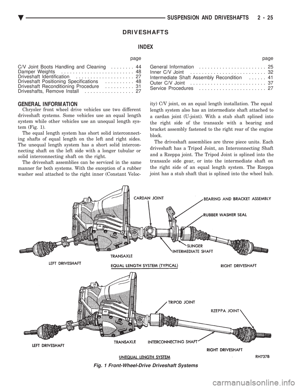
Chrysler front wheel drive vehicles use two different
driveshaft systems. Some vehicles use an equal length
system while other vehicles use an unequal length sys-
tem (Fig. 1). The equal length system has short solid interconnect-
ing shafts of equal length on the left and right sides.
The unequal length system has a short solid intercon-
necting shaft on the left side with a longer tubular or
solid interconnecting shaft on the right.
The driveshaft assemblies can be serviced in the same
manner for both systems. With the exception of a rubber
washer seal attached to the right inner (Constant Veloc- ity) C/V joint, on an equal length installation. The equal
length system also has an intermediate shaft attached to
a cardan joint (U-joint). With a stub shaft splined into
the right side of the transaxle with a bearing and
bracket assembly fastened to the right rear of the engine
block.
The driveshaft assemblies are three piece units. Each
driveshaft has a Tripod Joint, an Interconnecting Shaft
and a Rzeppa joint. The Tripod Joint is splined into the
transaxle side gear, or into the intermediate shaft on
the right side of an equal length system. The Rzeppa
joint has a stub shaft that is splined into the wheel hub.
Fig. 1 Front-Wheel-Drive Driveshaft Systems
Ä SUSPENSION AND DRIVESHAFTS 2 - 25
Page 86 of 2438

CAUTION: Do not pry on or otherwise damage wear
sleeve on outer C/V joint. (5) Support assembly at C/V joint housings. Re-
move by pulling outward on the inner joint housing. DO NOT PULL ON SHAFT (Figs. 10 and 11).
The driveshaft, when installed, acts as a bolt and
secures the hub/bearing assembly. If the vehicle is to
be supported or moved on its wheels, install a bolt
through the hub to ensure that the hub bearing as-
sembly cannot loosen.
DRIVESHAFT ASSEMBLIES INSTALL
CAUTION: See Wear Sleeve and Seal Lubrication in
Front Suspension and at end of this Group BE-
FORE driveshaft installation.
Fig. 6 Remove Speedometer Pinion Clamp (For Right Driveshaft).
Fig. 7 Remove Ball Joint to Steering Knuckle Clamp Bolt
Fig. 8 Separate Ball Joint from Knuckle
Fig. 9 Separate Outer C/V Joint Shaft from Hub
Fig. 10 Removing Driveshaft Assembly UnequalLength
2 - 28 SUSPENSION AND DRIVESHAFTS Ä
Page 88 of 2438

not to allow dirt to enter or grease to leave the boot
cavity. The clamp must be removed and discarded be-
fore the rod can be inserted. After venting, install a
new Service Clamp. (See Boots Install section at the
end of this group for details).
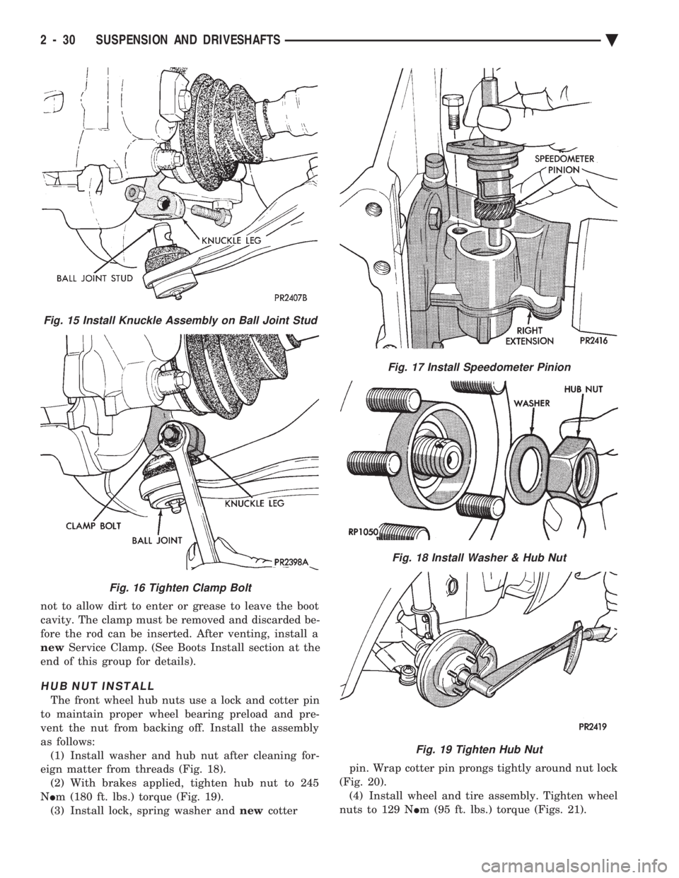
HUB NUT INSTALL
The front wheel hub nuts use a lock and cotter pin
to maintain proper wheel bearing preload and pre-
vent the nut from backing off. Install the assembly
as follows: (1) Install washer and hub nut after cleaning for-
eign matter from threads (Fig. 18). (2) With brakes applied, tighten hub nut to 245
N Im (180 ft. lbs.) torque (Fig. 19).
(3) Install lock, spring washer and newcotter pin. Wrap cotter pin prongs tightly around nut lock
(Fig. 20). (4) Install wheel and tire assembly. Tighten wheel
nuts to 129 N Im (95 ft. lbs.) torque (Figs. 21).
Fig. 15 Install Knuckle Assembly on Ball Joint Stud
Fig. 16 Tighten Clamp Bolt
Fig. 17 Install Speedometer Pinion
Fig. 18 Install Washer & Hub Nut
Fig. 19 Tighten Hub Nut
2 - 30 SUSPENSION AND DRIVESHAFTS Ä
Page 115 of 2438

REAR AXLE ASSEMBLY
REMOVE
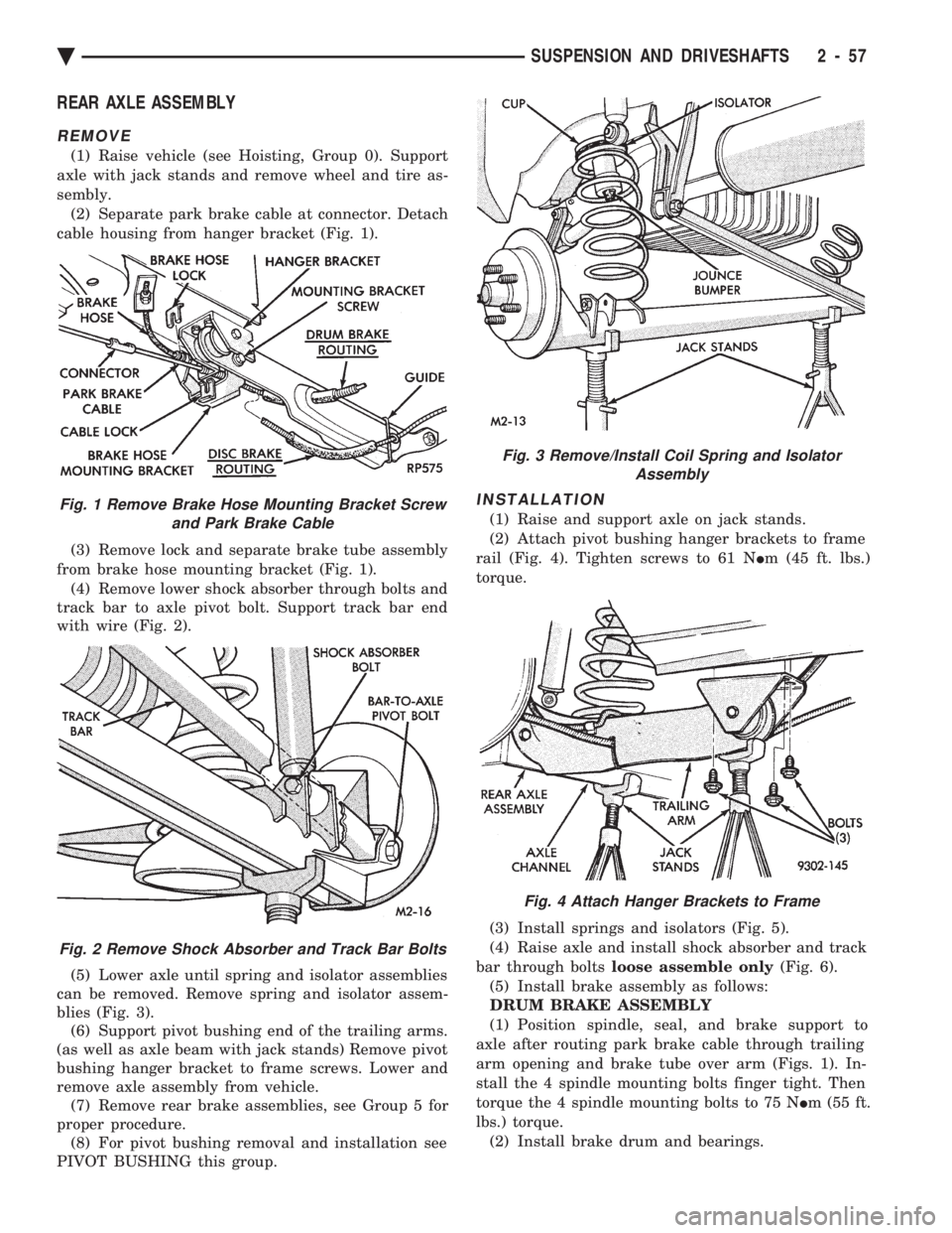
(1) Raise vehicle (see Hoisting, Group 0). Support
axle with jack stands and remove wheel and tire as-
sembly. (2) Separate park brake cable at connector. Detach
cable housing from hanger bracket (Fig. 1).
(3) Remove lock and separate brake tube assembly
from brake hose mounting bracket (Fig. 1). (4) Remove lower shock absorber through bolts and
track bar to axle pivot bolt. Support track bar end
with wire (Fig. 2).
(5) Lower axle until spring and isolator assemblies
can be removed. Remove spring and isolator assem-
blies (Fig. 3). (6) Support pivot bushing end of the trailing arms.
(as well as axle beam with jack stands) Remove pivot
bushing hanger bracket to frame screws. Lower and
remove axle assembly from vehicle. (7) Remove rear brake assemblies, see Group 5 for
proper procedure. (8) For pivot bushing removal and installation see
PIVOT BUSHING this group.
INSTALLATION
(1) Raise and support axle on jack stands.
(2) Attach pivot bushing hanger brackets to frame
rail (Fig. 4). Tighten screws to 61 N Im (45 ft. lbs.)
torque.
(3) Install springs and isolators (Fig. 5).
(4) Raise axle and install shock absorber and track
bar through bolts loose assemble only (Fig. 6).
(5) Install brake assembly as follows:
DRUM BRAKE ASSEMBLY
(1) Position spindle, seal, and brake support to
axle after routing park brake cable through trailing
arm opening and brake tube over arm (Figs. 1). In-
stall the 4 spindle mounting bolts finger tight. Then
torque the 4 spindle mounting bolts to 75 N Im (55 ft.
lbs.) torque. (2) Install brake drum and bearings.Fig. 1 Remove Brake Hose Mounting Bracket Screw and Park Brake Cable
Fig. 2 Remove Shock Absorber and Track Bar Bolts
Fig. 3 Remove/Install Coil Spring and Isolator Assembly
Fig. 4 Attach Hanger Brackets to Frame
Ä SUSPENSION AND DRIVESHAFTS 2 - 57