1993 CHEVROLET PLYMOUTH ACCLAIM oil pressure
[x] Cancel search: oil pressurePage 2000 of 2438
FLUID LEVEL AND CONDITION
The transmission and differential sump have a
common oil sump with a communicating opening
between the two. Before removing the dipstick, wipe all dirt off of the
protective disc and the dipstick handle. The torque converter will fill in both the PPark or N
Neutral positions. Place the selector lever in PPark to
check fluid level. Inspect fluid level on dipstick every six months.
Allow the engine to idle for at least one minute
with vehicle on level ground. This will assure
complete oil level stabilization between differen-
tial and transmission. A properly filled transaxle
will read near the addmark when fluid temperature is
21 degrees Celsius (70 degrees Fahrenheit). When the
transaxle reaches operating temperature the fluid
should be in the HOTregion.
Low fluid level can cause a variety of conditions
because it allows the pump to take in air along with the
fluid. As in any hydraulic system, air bubbles make the
fluid spongy, therefore, pressures will be low and build
up slowly. Improper filling can also raise the fluid level too
high. When the transaxle has too much fluid, the gears
churn up foam and cause the same conditions which
occur with a low fluid level. In either case, the air bubbles can cause overheating,
fluid oxidation, and varnishing, which can interfere
with normal valve, clutch, and servo operation. Foam-
ing can also result in fluid escaping from the transaxle
vent (dipstick handle) where it may be mistaken for a
leak. Along with fluid level, it is important to check the
condition of the fluid. When the fluid smells burned,
and is contaminated with metal or friction material
particles, a complete transaxle overhaul is needed. Be
sure to examine the fluid on the dipstick closely. If
there is any doubt about its condition, drain out a
sample for a double check. After the fluid has been checked, seat the dipstick
fully to seal out water and dirt.
SELECTION OF LUBRICANT
It is important that the proper lubricant be used in
these transmissions. MOPAR tATF PLUS (Automatic
Transmission Fluid-Type 7176) should be used to aid in
assuring optimum transmission performance. Fluids of
the type labeled DEXRON II Automatic Transmission
Fluid should be used only if the recommended fluid is
not available. It is important that the transmission
fluid be maintained at the prescribed level using the
recommended fluids.
SPECIAL ADDITIVES
Chrysler Corporation does not recommend the addi-
tion of any fluids to the transmission, other than the
automatic transmission fluid listed above. An ex- ception to this policy is the use of special dyes to aid in
detecting fluid leaks. The use of transmission sealers
should be avoided, since they may adversely affect
seals.
FLUID AND FILTER CHANGE
When the factory fill fluid is changed, only
fluids of the type labeled MOPAR tATF PLUS
(Automatic Transmission fluid) Type 7176 should
be used. A band adjustment and filter change
should be made at the time of the oil change. The
magnet (on the inside of the oil pan) should also
be cleaned with a clean, dry cloth. If the transaxle is disassembled for any reason,
the fluid and filter should be changed, and the
band(s) adjusted.
FLUID DRAIN AND REFILL
(1) Raise vehicle on a hoist (See Lubrication, Group
0). Place a drain container with a large opening, under
transaxle oil pan. (2) Loosen pan bolts and tap the pan at one corner to
break it loose allowing fluid to drain, then remove the
oil pan. (3) Install a new filter and gasket on bottom of the
valve body and tighten retaining screws to 5 N Im (40
in. lbs.). (4) Clean the oil pan and magnet. Reinstall pan
using new MOPAR tAdhesive sealant. Tighten oil pan
bolts to 19 N Im (165 in. lbs.).
(5) Pour four quarts of MOPAR tATF PLUS (Auto-
matic Transmission Fluid) Type 7176 through the
dipstick opening. (6) Start engine and allow to idle for at least one
minute. Then, with parking and service brakes ap-
plied, move selector lever momentarily to each posi-
tion, ending in the park or neutral position. (7) Add sufficient fluid to bring level to 1/8 inch
below the ADD mark. Recheck fluid level after transaxle is at normal
operating temperature. The level should be in the HOT
region (Fig. 1). To prevent dirt from entering transaxle, make cer-
tain that dipstick is full seated into the dipstick open-
ing.
TORQUE CONVERTER CLUTCH SOLENOID WIRING
CONNECTOR
If wiring connector is unplugged, the torque con-
verter clutch will not operate (Fig. 2).
ROAD TEST
Prior to performing a road test, be certain that the
fluid level and condition, and control cable adjustments
have been checked and approved. During the road test, the transaxle should be oper-
ated in each position to check for slipping and any
variation in shifting.
21 - 40 TRANSAXLE Ä
Page 2003 of 2438
(3) Move selector lever on transaxle one detent
forward from full rearward position. This is selector
2 position.
(4) Read pressures on both gauges as throttle lever
on transaxle is moved from full clockwise position to
full counterclockwise position. (5) Line pressure should read 52 to 58 psi with
throttle lever clockwise and gradually increase, as le-
ver is moved counterclockwise, to 80 to 88 psi. (6) Lubrication pressure should be 10 to 25 psi
with lever clockwise and 10 to 35 psi with lever full
counterclockwise. (7) This tests pump output, pressure regulation,
and condition of rear clutch and lubrication hydrau-
lic circuits.
TEST THREE (SELECTOR IN D)
(1) Attach gauges to lineandkickdown release
ports (Fig. 3). (2) Operate engine at 1600 rpm for test.
(3) Move selector lever on transaxle two detents
forward from full rearward position. This is selector
D position.
(4) Read pressures on both gauges as throttle lever
on transaxle is moved from full clockwise position to
full counterclockwise position. (5) Line pressure should read 52 to 58 psi with
throttle lever clockwise and gradually increase, as le-
ver is moved counterclockwise to 80 to 88 psi. (6) Kickdown release is pressurized only in direct
drive and should be same as line pressure within 3
psi, up to kickdown point. (7) This tests pump output, pressure regulation,
and condition of rear clutch, front clutch, and hy-
draulic circuits.
TEST FOUR (SELECTOR IN REVERSE)
(1) Attach 300 psi gauge to low-reverseport (Fig.
3). (2) Operate engine at 1600 rpm for test.
(3) Move selector lever on transaxle four detents
forward from full rearward position. This is selector
R position.
(4) Low-reverse pressure should read 180 to 220
psi with throttle lever clockwise and gradually in-
crease, as lever is moved counterclockwise to 260 to
300 psi. (5) This tests pump output, pressure regulation,
and condition of front clutch and rear servo hydraulic
circuits. (6) Move selector lever on transaxle to Dposition
to check that low-reverse pressure drops to zero. (7) This tests for leakage into rear servo, due to
case porosity, which can cause reverse band burn
out.
TEST RESULT INDICATIONS
(1) If proper line pressure, minimum to maximum, is
found in any one test, the pump and pressure regulator
are working properly. (2) Low pressure in D, 1, and 2but correct pressure
in Rindicates rear clutch circuit leakage.
(3) Low pressure in D and Rbut correct pressure in
1 indicates front clutch circuit leakage.
(4) Low pressure in R and 1but correct pressure in
2 indicates rear servo circuit leakage.
(5) Low line pressure in all positions indicates a
defective pump, a clogged filter, or a stuck pressure
regulator valve.
GOVERNOR PRESSURE
Test only if transaxle shifts at wrong vehicle speeds
when throttle cable is correctly adjusted. (1) Connect a 0-150 psi pressure gauge to governor
pressure take-off point, located at lower right side of
case, below differential cover (Fig. 3). (2) Operate transaxle in third gear to read pres-
sures. The governor pressure should respond smoothly
to changes in mph and should return to 0 to 3 psi when vehicle is stopped. High pressure at
standstill (above 3 psi) will prevent the transaxle from
downshifting.
THROTTLE PRESSURE
No gauge port is provided for throttle pressure.
Incorrect throttle pressure should only be suspected if
part throttle upshift speeds are either delayed or occur
too early, with a correctly adjusted throttle cable.
Engine runaway on either upshifts or downshifts can
also be an indicator of incorrect (low) throttle pressure
setting, or misadjusted throttle cable. In no case should throttle pressure be adjusted until
the transaxle throttle cable adjustment has been veri-
fied to be correct.
CLUTCH AND SERVO AIR PRESSURE TESTS
A no drive condition might exist even with correct
fluid pressure, because of inoperative clutches or
bands. The inoperative units, clutches, bands, and
servos can be located through a series of tests by
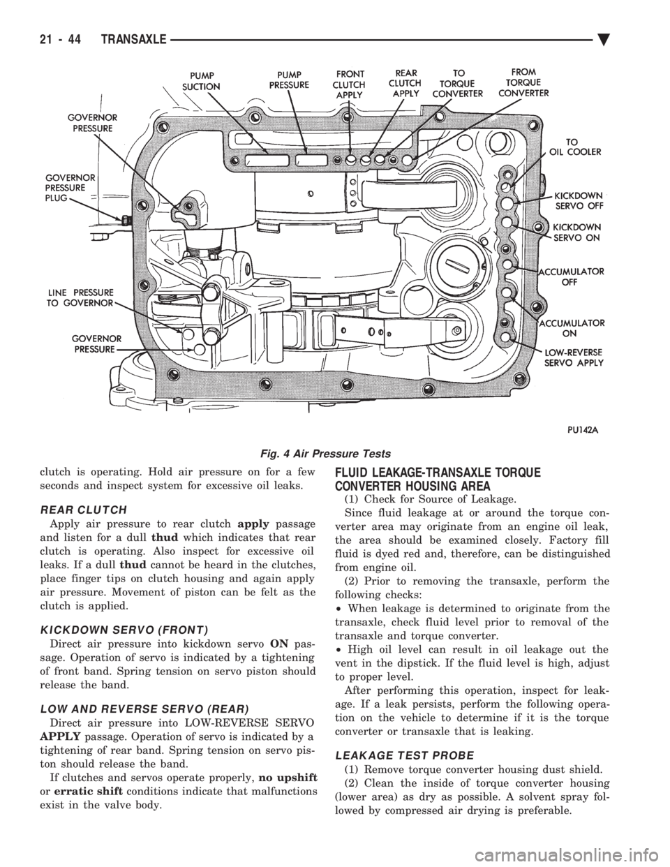
substituting air pressure for fluid pressure (Fig. 4). The front and rear clutches, kickdown servo, and
low-reverse servo may be tested by applying air pres-
sure to their respective passages after the valve body assembly has been removed. To make
air pressure tests, proceed as follows: Compressed air supply must be free of all dirt
or moisture. Use a pressure of 30 psi. Remove oil pan and valve body See Disassembly-
Subassembly Removal .
FRONT CLUTCH
Apply air pressure to front clutch applypassage and
listen for a dull thudwhich indicates that front
Ä TRANSAXLE 21 - 43
Page 2004 of 2438
clutch is operating. Hold air pressure on for a few
seconds and inspect system for excessive oil leaks.
REAR CLUTCH
Apply air pressure to rear clutch applypassage
and listen for a dull thudwhich indicates that rear
clutch is operating. Also inspect for excessive oil
leaks. If a dull thudcannot be heard in the clutches,
place finger tips on clutch housing and again apply
air pressure. Movement of piston can be felt as the
clutch is applied.
KICKDOWN SERVO (FRONT)
Direct air pressure into kickdown servo ONpas-
sage. Operation of servo is indicated by a tightening
of front band. Spring tension on servo piston should
release the band.
LOW AND REVERSE SERVO (REAR)
Direct air pressure into LOW-REVERSE SERVO
APPLY passage. Operation of servo is indicated by a
tightening of rear band. Spring tension on servo pis-
ton should release the band. If clutches and servos operate properly, no upshift
or erratic shift conditions indicate that malfunctions
exist in the valve body.
FLUID LEAKAGE-TRANSAXLE TORQUE
CONVERTER HOUSING AREA
(1) Check for Source of Leakage.
Since fluid leakage at or around the torque con-
verter area may originate from an engine oil leak,
the area should be examined closely. Factory fill
fluid is dyed red and, therefore, can be distinguished
from engine oil. (2) Prior to removing the transaxle, perform the
following checks:
² When leakage is determined to originate from the
transaxle, check fluid level prior to removal of the
transaxle and torque converter.
² High oil level can result in oil leakage out the
vent in the dipstick. If the fluid level is high, adjust
to proper level. After performing this operation, inspect for leak-
age. If a leak persists, perform the following opera-
tion on the vehicle to determine if it is the torque
converter or transaxle that is leaking.
LEAKAGE TEST PROBE
(1) Remove torque converter housing dust shield.
(2) Clean the inside of torque converter housing
(lower area) as dry as possible. A solvent spray fol-
lowed by compressed air drying is preferable.
Fig. 4 Air Pressure Tests
21 - 44 TRANSAXLE Ä
Page 2005 of 2438
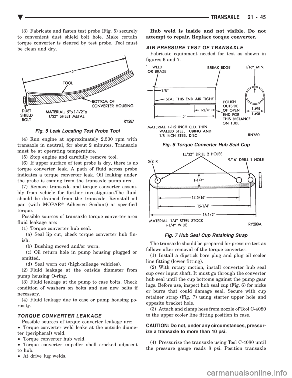
(3) Fabricate and fasten test probe (Fig. 5) securely
to convenient dust shield bolt hole. Make certain
torque converter is cleared by test probe. Tool must
be clean and dry.
(4) Run engine at approximately 2,500 rpm with
transaxle in neutral, for about 2 minutes. Transaxle
must be at operating temperature. (5) Stop engine and carefully remove tool.
(6) If upper surface of test probe is dry, there is no
torque converter leak. A path of fluid across probe
indicates a torque converter leak. Oil leaking under
the probe is coming from the transaxle pump area. (7) Remove transaxle and torque converter assem-
bly from vehicle for further investigation.The fluid
should be drained from the transaxle. Reinstall oil
pan (with MOPAR tAdhesive Sealant) at specified
torque. Possible sources of transaxle torque converter area
fluid leakage are: (1) Torque converter hub seal.(a) Seal lip cut, check torque converter hub fin-
ish. (b) Bushing moved and/or worn.
(c) Oil return hole in pump housing plugged or
omitted. (d) Seal worn out (high-mileage vehicles).
(2) Fluid leakage at the outside diameter from
pump housing O-ring. (3) Fluid leakage at the pump to case bolts. Check
condition of washers on bolts and use new bolts if
necessary. (4) Fluid leakage due to case or pump housing po-
rosity.
TORQUE CONVERTER LEAKAGE
Possible sources of torque converter leakage are:
² Torque converter weld leaks at the outside diame-
ter (peripheral) weld.
² Torque converter hub weld.
² Torque converter impeller shell cracked adjacent
to hub.
² At drive lug welds. Hub weld is inside and not visible. Do not
attempt to repair. Replace torque converter.
AIR PRESSURE TEST OF TRANSAXLE
Fabricate equipment needed for test as shown in
figures 6 and 7.
The transaxle should be prepared for pressure test as
follows after removal of the torque converter: (1) Install a dipstick bore plug and plug oil cooler
line fitting (lower fitting). (2) With rotary motion, install converter hub seal
cup over input shaft. It must go through the converter
hub seal until the cup bottoms against the pump gear
lugs. Before use, inspect hub seal cup (Fig. 6) for nicks
or burrs that could damage seal. Secure with cup
retainer strap (Fig. 7) using starter upper hole and
opposite bracket hole. (3) Attach and clamp hose from nozzle of Tool C-4080
to the upper cooler line fitting position in case.
CAUTION: Do not, under any circumstances, pressur-
ize a transaxle to more than 10 psi. (4) Pressurize the transaxle using Tool C-4080 until
the pressure gauge reads 8 psi. Position transaxle
Fig. 5 Leak Locating Test Probe Tool
Fig. 6 Torque Converter Hub Seal Cup
Fig. 7 Hub Seal Cup Retaining Strap
Ä TRANSAXLE 21 - 45
Page 2017 of 2438
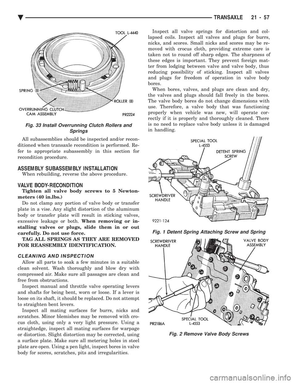
All subassemblies should be inspected and/or recon-
ditioned when transaxle recondition is performed. Re-
fer to appropriate subassembly in this section for
recondition procedure.
ASSEMBLY SUBASSEMBLY INSTALLATION
When rebuilding, reverse the above procedure.
VALVE BODY-RECONDITION
Tighten all valve body screws to 5 Newton-
meters (40 in.lbs.) Do not clamp any portion of valve body or transfer
plate in a vise. Any slight distortion of the aluminum
body or transfer plate will result in sticking valves,
excessive leakage or both. When removing or in-
stalling valves or plugs, slide them in or out
carefully. Do not use force. TAG ALL SPRINGS AS THEY ARE REMOVED
FOR REASSEMBLY IDENTIFICATION.
CLEANING AND INSPECTION
Allow all parts to soak a few minutes in a suitable
clean solvent. Wash thoroughly and blow dry with
compressed air. Make sure all passages are clean and
free from obstructions. Inspect manual and throttle valve operating levers
and shafts for being bent, worn or loose. If a lever is
loose on its shaft, it should be replaced. Do not attempt
to straighten bent levers. Inspect all mating surfaces for burrs, nicks and
scratches. Minor blemishes may be removed with cro-
cus cloth, using only a very light pressure. Using a
straightedge, inspect all mating surfaces for warpage
or distortion. Slight distortion may be corrected, using
a surface plate. Make sure all metering holes in steel
plate are open. Using a pen light, inspect bores in valve
body for scores, scratches, pits and irregularities. Inspect all valve springs for distortion and col-
lapsed coils. Inspect all valves and plugs for burrs,
nicks, and scores. Small nicks and scores may be re-
moved with crocus cloth, providing extreme care is
taken not to round off sharp edges. The sharpness of
these edges is important. They prevent foreign mat-
ter from lodging between valve and valve body, thus
reducing possibility of sticking. Inspect all valves
and plugs for freedom of operation in valve body
bores. When bores, valves, and plugs are clean and dry,
the valves and plugs should fall freely in the bores.
The valve body bores do not change dimensions with
use. Therefore, a valve body that was functioning
properly when vehicle was new, will operate cor-
rectly if it is properly and thoroughly cleaned. There
is no need to replace valve body unless it is damaged
in handling.
Fig. 1 Detent Spring Attaching Screw and Spring
Fig. 2 Remove Valve Body Screws
Fig. 33 Install Overrunning Clutch Rollers and Springs
Ä TRANSAXLE 21 - 57
Page 2045 of 2438
41TE FOUR SPEED AUTOMATIC TRANSAXLE INDEX
page page
41TE Transaxle General Diagnosis ........... 88
Aluminum Thread Repair ................... 98
Bearing Adjustment Procedure .............. 141
Clutch Air Pressure Tests .................. 95
Coolers and Tubes Reverse Flushing ......... 98
Diagnosis Chart ``B'' ....................... 90
Diagnosis Trouble Code Chart ``A'' ............ 89
Differential Repair ....................... 136
Fluid and Filter Changes ................... 93
Fluid Drain and Refill ..................... 93
Fluid Leakage-Torque Converter Housing Area . . 97
Fluid Level and Condition .................. 93
Gearshift Linkage Adjustment ............... 98
General Information ....................... 85
Hydraulic Pressure Tests ................... 94
Input Clutches-Recondition ................ 121
Oil Cooler Flow Check .................... 99 Oil Pump Seal Replace
................... 136
Park/Neutral Position Switch ............... 102
Pinion Factor Procedure .................. 104
Road Test .............................. 93
Selection of Lubricant ..................... 93
Solenoid Assembly-Replace ................ 101
Special Additives ......................... 93
Speed Sensor-Input ...................... 102
Speed Sensor-Output .................... 103
Torque Converter Clutch Break-In Procedure . . . 104
Transaxle Quick Learn Procedure ........... 103
Transaxle Recondition .................... 105
Transaxle Removal and Installation ........... 99
Transmission Control Module ............... 103
Transmission Range Switch ................ 102
Valve Body-Recondition ................... 132
GENERAL INFORMATION
The 41TE four-speed FWD transaxle uses fully-
adaptive controls. Adaptive controls are those which
perform their functions based on real-time feedback
sensor information. The transaxle uses hydraulically
applied clutches to shift a planetary gear train.
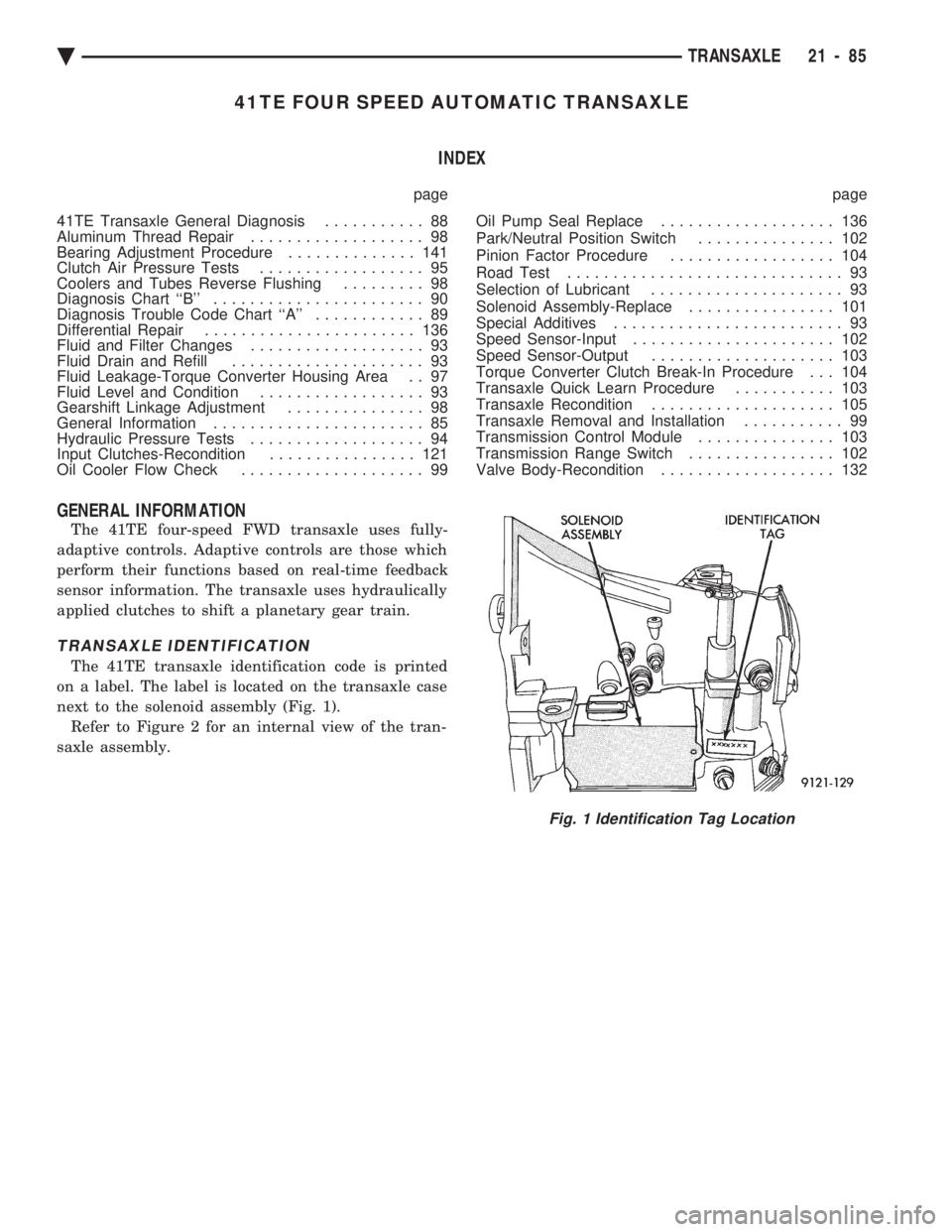
TRANSAXLE IDENTIFICATION
The 41TE transaxle identification code is printed
on a label. The label is located on the transaxle case
next to the solenoid assembly (Fig. 1). Refer to Figure 2 for an internal view of the tran-
saxle assembly.
Fig. 1 Identification Tag Location
Ä TRANSAXLE 21 - 85
Page 2047 of 2438
OPERATION
The 41TE transaxle provides forward ratios of 2.84,
1.57, 1.00, and 0.69 with torque converter clutch
available in 2nd, direct, or overdrive gear; the Re-
verse ratio is 2.21. The shift lever is conventional
with six positions: P, R, N, OD, 3, and L. When OD
is selected the transaxle shifts normally through all
four speeds with torque converter clutch available in
overdrive; this position is recommended for most
driving. The 3 position is tailored for use in hilly or
mountainous driving. When 3 is selected, the trans-
mission uses only 1st, 2nd, and direct gears with
2nd-direct shift delayed to 40 mph or greater. When
operating in 3 or L positions torque converter clutch
application occurs in direct gear for improved trans-
mission cooling under heavy loads. If high engine
coolant temperature occurs, the torque converter
clutch will also engage in 2nd gear. The L position
provides maximum engine braking for descending
steep grades. Unlike most current transaxles, up-
shifts are provided to 2nd or direct gear at peak en-
gine speeds if the accelerator is depressed. This
provides engine over-speed protection and maximum
performance.
CLUTCH AND GEAR
The transaxle consists of:
² Three multiple disc input clutches
² Two multiple disc grounded clutches
² Four hydraulic accumulators
² Two planetary gear sets
This provides four forward ratios and a reverse ra-
tio. The clutch-apply pistons were designed with cen-
trifugally balanced oil cavities so that quick response
and good control can be achieved at any speed. A
push/pull piston is incorporated for two of the three
input clutches.
CAUTION: Some clutch packs appear similar, but
they are not the same. Do not interchange clutch
components as they might fail.
HYDRAULICS
The hydraulics of the transaxle provide the manual
shift lever select function, main line pressure regula-
tion, and torque converter and cooler flow control.
Oil flow to the friction elements is controlled directly
by four solenoid valves. The hydraulics also include a
unique logic-controlled ``solenoid torque converter
clutch control valve''. This valve locks out the 1st
gear reaction element with the application of 2nd, di-
rect, or overdrive gear elements. It also redirects the
1st gear solenoid output so that it can control torque
converter clutch operation. To regain access to 1st
gear, a special sequence of solenoid commands must
be used to unlock and move the solenoid torque con-
verter clutch control valve. This precludes any appli- cation of the 1st gear reaction element with other
elements applied. It also allows one solenoid to con-
trol two friction elements.
Small, high-rate accumulators are provided in each
controlled friction element circuit. These serve to ab-
sorb the pressure responses, and allow the controls to
read and respond to changes that are occurring.
SOLENOIDS
Since the solenoid valves perform virtually all con-
trol functions, these valves must be extremely dura-
ble and tolerant of normal dirt particles. For that
reason hardened-steel poppet and ball valves are
used. These are free from any close operating clear-
ances, and the solenoids operate the valves directly
without any intermediate element. Direct operation
means that these units must have very high output
so that they can close against the sizeable flow areas
and high line pressures. Fast response is also re-
quired to meet the control requirements. Two of the solenoids are normally-venting and two
are normally-applying; this was done to provide a de-
fault mode of operation. With no electrical power, the
transmission provides 2nd gear in OD, 3,orLshift
lever positions. All other transmission lever positions
will operate normally. The choice of 2nd gear was
made to provide adequate breakaway performance
while still accommodating highway speeds.
SENSORS
There are three pressure switches to identify sole-
noid application and two speed sensors to read input
(torque converter turbine) and output (parking sprag)
speeds. There is also a position switch to indicate the
manual shift lever position. The pressure switches
are incorporated in an assembly with the solenoids.
Engine speed, throttle position, temperature, etc., are
also observed. Some of these signals are read directly
from the engine control sensors; others are read from
a multiplex circuit with the powertrain control mod-
ule.
ELECTRONICS
The 41TE transmission control module is located
underhood in a potted, die-cast aluminum housing
with a sealed, 60-way connector.
ELECTRONIC MODULATED CONVERTER CLUTCH (EMCC)
The EMCC enables the torque converter clutch to
partially engage between 23 to 47 MPH before full
engagement at about 50 MPH and beyond. This fea-
ture is on all vehicles equipped with the 41TE tran-
saxle.
ADAPTIVE CONTROLS
These controls function by reading the input and
output speeds over 140 times a second and respond-
Ä TRANSAXLE 21 - 87
Page 2053 of 2438
FLUID LEVEL AND CONDITION
The transmission and differential sump have a
common oil sump with a communicating opening
between the two. The torque converter fills in both the PPark and N
Neutral positions. Place the selector lever in PPark to
check the fluid level. The engine should be running
at idle speed for at least one minute, with the
vehicle on level ground. This will assure com-
plete oil level stabilization between differential
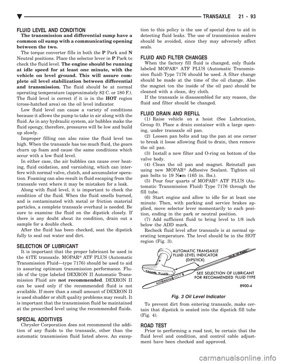
and transmission. The fluid should be at normal
operating temperature (approximately 82 C. or 180 F.).
The fluid level is correct if it is in the HOTregion
(cross-hatched area) on the oil level indicator. Low fluid level can cause a variety of conditions
because it allows the pump to take in air along with the
fluid. As in any hydraulic system, air bubbles make the
fluid spongy, therefore, pressures will be low and build
up slowly. Improper filling can also raise the fluid level too
high. When the transaxle has too much fluid, the gears
churn up foam and cause the same conditions which
occur with a low fluid level. In either case, the air bubbles can cause over heat-
ing, fluid oxidation, and varnishing, which can inter-
fere with normal valve, clutch, and accumulator opera-
tion. Foaming can also result in fluid escaping from the
transaxle vent where it may be mistaken for a leak. Along with fluid level, it is important to check the
condition of the fluid. When the fluid smells burned,
and is contaminated with metal or friction material
particles, a complete transaxle overhaul is needed. Be
sure to examine the fluid on the dipstick closely. If
there is any doubt about its condition, drain out a
sample for a double check. After the fluid has been checked, seat the dipstick
fully to seal out water and dirt.
SELECTION OF LUBRICANT
It is important that the proper lubricant be used in
the 41TE transaxle. MOPAR tATF PLUS (Automatic
Transmission FluidÐtype 7176) should be used to aid
in assuring optimum transmission performance. Flu-
ids of the type labeled DEXRON II Automatic Trans-
mission Fluid are not recommended . DEXRON II
can be used only if the recommended fluid is not
available. If more than a small amount of DEXRON II
is used shudder or shift quality problems may result. It
is important that the transmission fluid be maintained
at the prescribed level using the recommended fluids.
SPECIAL ADDITIVES
Chrysler Corporation does not recommend the addi-
tion of any fluids to the transaxle, other than the
automatic transmission fluid listed above. An excep- tion to this policy is the use of special dyes to aid in
detecting fluid leaks. The use of transmission sealers
should be avoided, since they may adversely affect
seals.
FLUID AND FILTER CHANGES
When the factory fill fluid is changed, only fluids
labeled MOPAR tATF PLUS (Automatic Transmis-
sion fluid) Type 7176 should be used. A filter change
should be made at the time of the oil change. Also
the magnet (on the inside of the oil pan) should be
cleaned with a clean, dry cloth. If the transaxle is disassembled for any reason, the
fluid and filter should be changed.
FLUID DRAIN AND REFILL
(1) Raise vehicle on a hoist (See Lubrication,
Group 0). Place a drain container with a large open-
ing, under transaxle oil pan. (2) Loosen pan bolts and tap the pan at one corner
to break it loose allowing fluid to drain, then remove
the oil pan. (3) Install a new filter and O-ring on bottom of the
valve body. (4) Clean the oil pan and magnet. Reinstall pan
using new MOPAR tAdhesive Sealant. Tighten oil
pan bolts to 19 N Im (165 in. lbs.).
(5) Pour four quarts of MOPAR tATF PLUS (Au-
tomatic Transmission Fluid) Type 7176 through the
fill tube. (6) Start engine and allow to idle for at least one
minute. Then, with parking and service brakes ap-
plied, move selector lever momentarily to each posi-
tion, ending in the park or neutral position. (7) Add sufficient fluid to bring level to 1/8 inch
below the ADD mark. Recheck fluid level after transaxle is at normal op-
erating temperature. The level should be in the HOT
region (Fig. 3).
To prevent dirt from entering transaxle, make cer-
tain that dipstick is seated into the dipstick fill tube
(Fig. 4).
ROAD TEST
Prior to performing a road test, be certain that the
fluid level and condition, and control cable adjust-
ment have been checked and approved.
Fig. 3 Oil Level Indicator
Ä TRANSAXLE 21 - 93