1993 CHEVROLET PLYMOUTH ACCLAIM oil pressure
[x] Cancel search: oil pressurePage 2054 of 2438
During the road test, the transaxle should be oper-
ated in each position to check for slipping and any
variation in shifting. If vehicle operates properly at highway speeds, but
has poor acceleration, the torque converter stator
overrunning clutch may be slipping. If through-gear
acceleration is normal, but high throttle opening is
required to maintain highway speeds, the torque con-
verter stator clutch may have seized. Both of these
stator defects require replacement of the torque con-
verter. The clutch that is slipping can be determined by
noting the transaxle operation in all selector posi-
tions. Then comparing which internal units are ap-
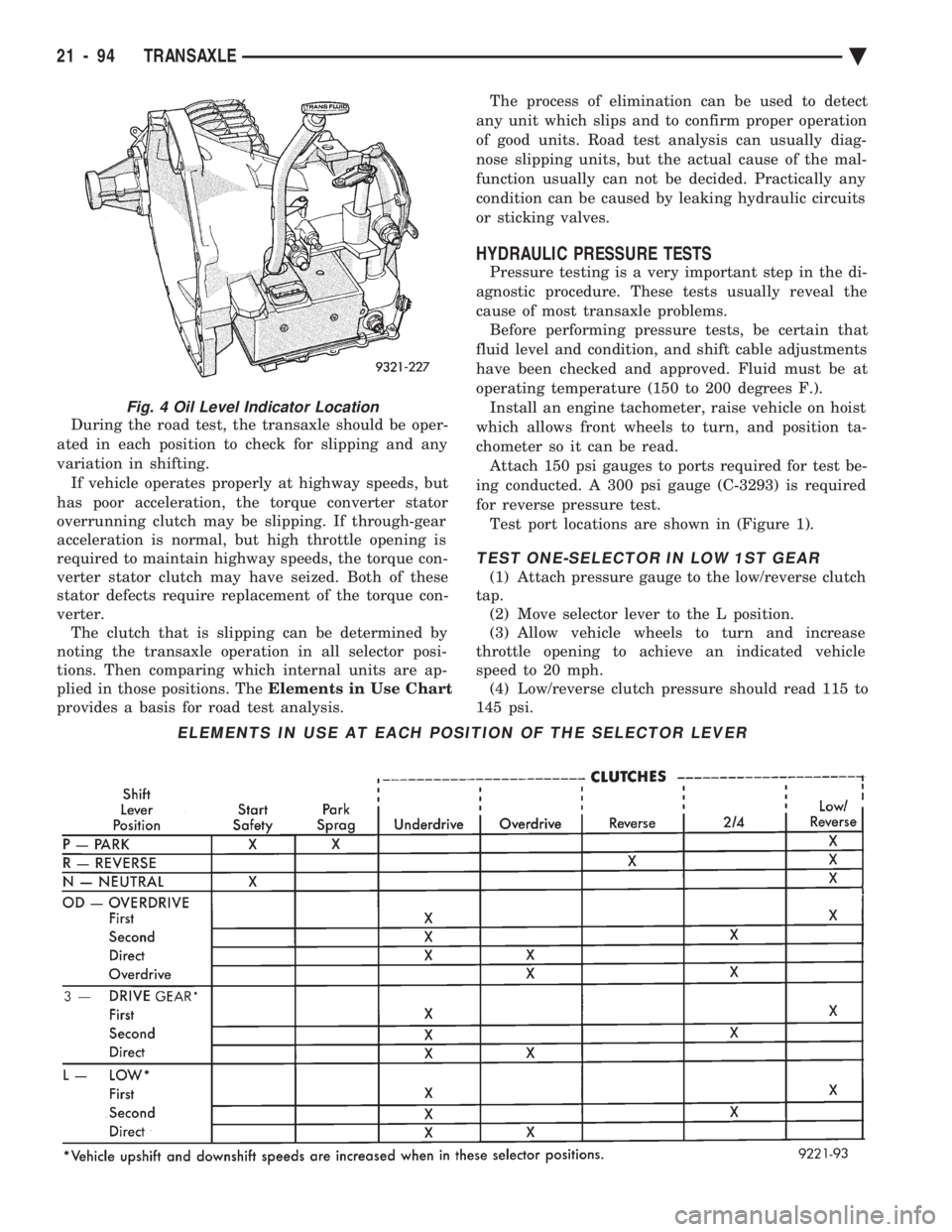
plied in those positions. The Elements in Use Chart
provides a basis for road test analysis. The process of elimination can be used to detect
any unit which slips and to confirm proper operation
of good units. Road test analysis can usually diag-
nose slipping units, but the actual cause of the mal-
function usually can not be decided. Practically any
condition can be caused by leaking hydraulic circuits
or sticking valves.
HYDRAULIC PRESSURE TESTS
Pressure testing is a very important step in the di-
agnostic procedure. These tests usually reveal the
cause of most transaxle problems. Before performing pressure tests, be certain that
fluid level and condition, and shift cable adjustments
have been checked and approved. Fluid must be at
operating temperature (150 to 200 degrees F.). Install an engine tachometer, raise vehicle on hoist
which allows front wheels to turn, and position ta-
chometer so it can be read. Attach 150 psi gauges to ports required for test be-
ing conducted. A 300 psi gauge (C-3293) is required
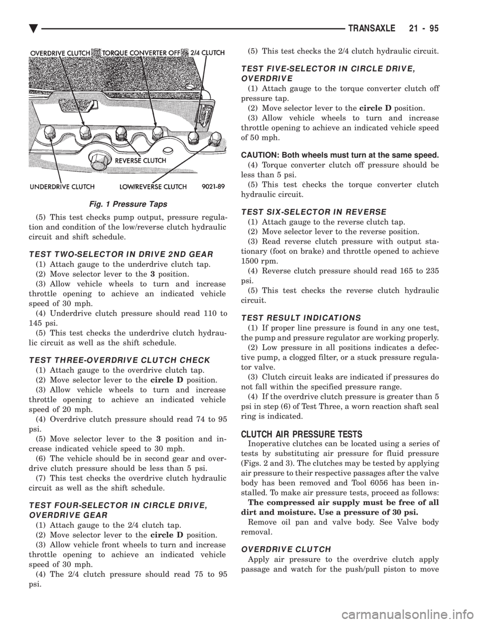
for reverse pressure test. Test port locations are shown in (Figure 1).
TEST ONE-SELECTOR IN LOW 1ST GEAR
(1) Attach pressure gauge to the low/reverse clutch
tap. (2) Move selector lever to the L position.
(3) Allow vehicle wheels to turn and increase
throttle opening to achieve an indicated vehicle
speed to 20 mph. (4) Low/reverse clutch pressure should read 115 to
145 psi.
ELEMENTS IN USE AT EACH POSITION OF THE SELECTOR LEVER
Fig. 4 Oil Level Indicator Location
21 - 94 TRANSAXLE Ä
Page 2055 of 2438
(5) This test checks pump output, pressure regula-
tion and condition of the low/reverse clutch hydraulic
circuit and shift schedule.
TEST TWO-SELECTOR IN DRIVE 2ND GEAR
(1) Attach gauge to the underdrive clutch tap.
(2) Move selector lever to the 3position.
(3) Allow vehicle wheels to turn and increase
throttle opening to achieve an indicated vehicle
speed of 30 mph. (4) Underdrive clutch pressure should read 110 to
145 psi. (5) This test checks the underdrive clutch hydrau-
lic circuit as well as the shift schedule.
TEST THREE-OVERDRIVE CLUTCH CHECK
(1) Attach gauge to the overdrive clutch tap.
(2) Move selector lever to the circle Dposition.
(3) Allow vehicle wheels to turn and increase
throttle opening to achieve an indicated vehicle
speed of 20 mph. (4) Overdrive clutch pressure should read 74 to 95
psi. (5) Move selector lever to the 3position and in-
crease indicated vehicle speed to 30 mph. (6) The vehicle should be in second gear and over-
drive clutch pressure should be less than 5 psi. (7) This test checks the overdrive clutch hydraulic
circuit as well as the shift schedule.
TEST FOUR-SELECTOR IN CIRCLE DRIVE, OVERDRIVE GEAR
(1) Attach gauge to the 2/4 clutch tap.
(2) Move selector lever to the circle Dposition.
(3) Allow vehicle front wheels to turn and increase
throttle opening to achieve an indicated vehicle
speed of 30 mph. (4) The 2/4 clutch pressure should read 75 to 95
psi. (5) This test checks the 2/4 clutch hydraulic circuit.
TEST FIVE-SELECTOR IN CIRCLE DRIVE,
OVERDRIVE
(1) Attach gauge to the torque converter clutch off
pressure tap. (2) Move selector lever to the circle Dposition.
(3) Allow vehicle wheels to turn and increase
throttle opening to achieve an indicated vehicle speed
of 50 mph.
CAUTION: Both wheels must turn at the same speed. (4) Torque converter clutch off pressure should be
less than 5 psi. (5) This test checks the torque converter clutch
hydraulic circuit.
TEST SIX-SELECTOR IN REVERSE
(1) Attach gauge to the reverse clutch tap.
(2) Move selector lever to the reverse position.
(3) Read reverse clutch pressure with output sta-
tionary (foot on brake) and throttle opened to achieve
1500 rpm. (4) Reverse clutch pressure should read 165 to 235
psi. (5) This test checks the reverse clutch hydraulic
circuit.
TEST RESULT INDICATIONS
(1) If proper line pressure is found in any one test,
the pump and pressure regulator are working properly. (2) Low pressure in all positions indicates a defec-
tive pump, a clogged filter, or a stuck pressure regula-
tor valve. (3) Clutch circuit leaks are indicated if pressures do
not fall within the specified pressure range. (4) If the overdrive clutch pressure is greater than 5
psi in step (6) of Test Three, a worn reaction shaft seal
ring is indicated.
CLUTCH AIR PRESSURE TESTS
Inoperative clutches can be located using a series of
tests by substituting air pressure for fluid pressure
(Figs. 2 and 3). The clutches may be tested by applying
air pressure to their respective passages after the valve
body has been removed and Tool 6056 has been in-
stalled. To make air pressure tests, proceed as follows: The compressed air supply must be free of all
dirt and moisture. Use a pressure of 30 psi. Remove oil pan and valve body. See Valve body
removal.
OVERDRIVE CLUTCH
Apply air pressure to the overdrive clutch apply
passage and watch for the push/pull piston to move
Fig. 1 Pressure Taps
Ä TRANSAXLE 21 - 95
Page 2057 of 2438
first separator plate and watch carefully for the pis-
ton to move forward. The piston should return to its
original position after the air pressure is removed.
UNDERDRIVE CLUTCH
Because this clutch piston cannot be seen, its oper-
ation is checked by function. Air pressure is applied
to the low/reverse and the 2/4 clutches. This locks
the output shaft. Use a piece of rubber hose wrapped
around the input shaft and a pair of clamp-on pliers
to turn the input shaft. Next apply air pressure to
the underdrive clutch. The input shaft should not ro-
tate with hand torque. Release the air pressure and
confirm that the input shaft will rotate.
FLUID LEAKAGE-TORQUE CONVERTER HOUSING
AREA
(1) Check for source of leakage.
Since fluid leakage at or around the torque con-
verter area may originate from an engine oil leak,
the area should be examined closely. Factory fill
fluid is dyed red and, therefore, can be distinguished
from engine oil. (2) Prior to removing the transaxle, perform the
following checks: When leakage is determined to originate from the
transaxle, check fluid level prior to removal of the
transaxle and torque converter. High oil level can result in oil leakage out the vent
in the manual shaft. If the fluid level is high, adjust
to proper level. After performing this operation, inspect for leak-
age. If a leak persists, perform the following opera-
tion on the vehicle to determine if it is the torque
converter or transaxle that is leaking.
LEAKAGE TEST PROBE
(1) Remove torque converter housing dust shield.
(2) Clean the inside of torque converter housing
(lower area) as dry as possible. A solvent spray fol-
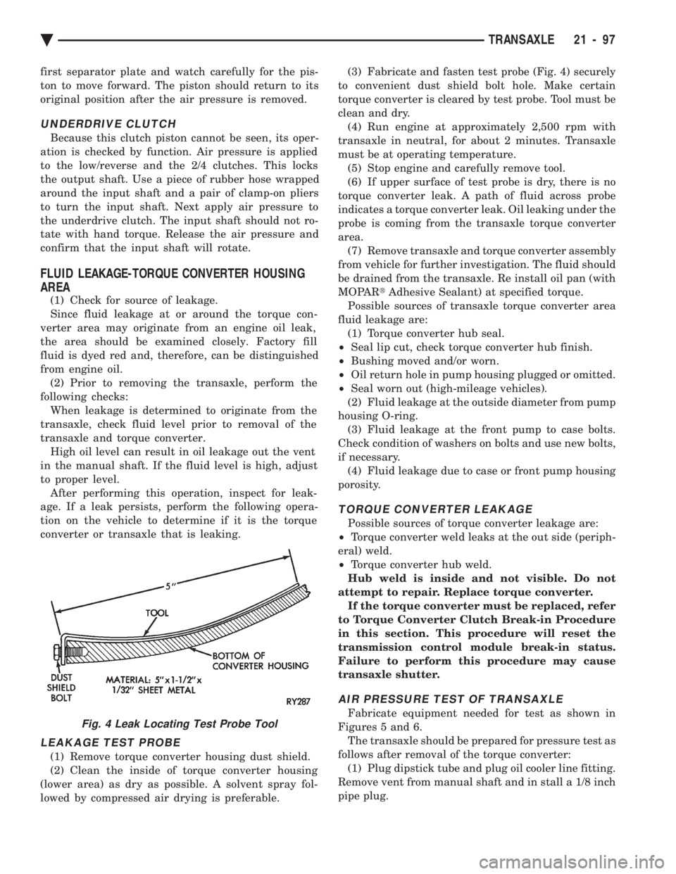
lowed by compressed air drying is preferable. (3) Fabricate and fasten test probe (Fig. 4) securely
to convenient dust shield bolt hole. Make certain
torque converter is cleared by test probe. Tool must be
clean and dry. (4) Run engine at approximately 2,500 rpm with
transaxle in neutral, for about 2 minutes. Transaxle
must be at operating temperature. (5) Stop engine and carefully remove tool.
(6) If upper surface of test probe is dry, there is no
torque converter leak. A path of fluid across probe
indicates a torque converter leak. Oil leaking under the
probe is coming from the transaxle torque converter
area. (7) Remove transaxle and torque converter assembly
from vehicle for further investigation. The fluid should
be drained from the transaxle. Re install oil pan (with
MOPAR tAdhesive Sealant) at specified torque.
Possible sources of transaxle torque converter area
fluid leakage are: (1) Torque converter hub seal.
² Seal lip cut, check torque converter hub finish.
² Bushing moved and/or worn.
² Oil return hole in pump housing plugged or omitted.
² Seal worn out (high-mileage vehicles).
(2) Fluid leakage at the outside diameter from pump
housing O-ring. (3) Fluid leakage at the front pump to case bolts.
Check condition of washers on bolts and use new bolts,
if necessary. (4) Fluid leakage due to case or front pump housing
porosity.
TORQUE CONVERTER LEAKAGE
Possible sources of torque converter leakage are:
² Torque converter weld leaks at the out side (periph-
eral) weld.
² Torque converter hub weld.
Hub weld is inside and not visible. Do not
attempt to repair. Replace torque converter. If the torque converter must be replaced, refer
to Torque Converter Clutch Break-in Procedure
in this section. This procedure will reset the
transmission control module break-in status.
Failure to perform this procedure may cause
transaxle shutter.
AIR PRESSURE TEST OF TRANSAXLE
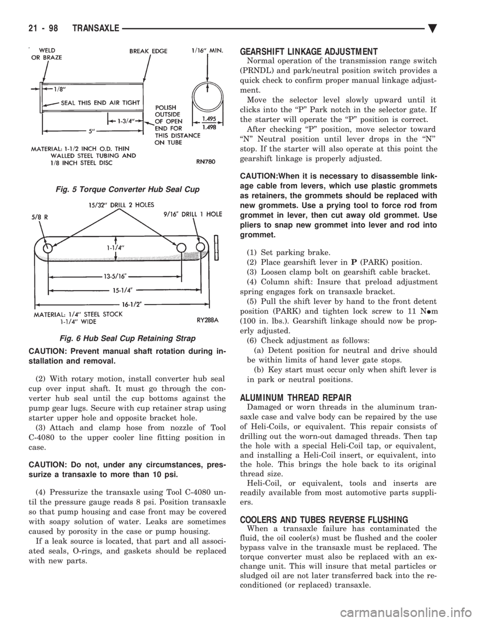
Fabricate equipment needed for test as shown in
Figures 5 and 6. The transaxle should be prepared for pressure test as
follows after removal of the torque converter: (1) Plug dipstick tube and plug oil cooler line fitting.
Remove vent from manual shaft and in stall a 1/8 inch
pipe plug.Fig. 4 Leak Locating Test Probe Tool
Ä TRANSAXLE 21 - 97
Page 2058 of 2438
CAUTION: Prevent manual shaft rotation during in-
stallation and removal. (2) With rotary motion, install converter hub seal
cup over input shaft. It must go through the con-
verter hub seal until the cup bottoms against the
pump gear lugs. Secure with cup retainer strap using
starter upper hole and opposite bracket hole. (3) Attach and clamp hose from nozzle of Tool
C-4080 to the upper cooler line fitting position in
case.
CAUTION: Do not, under any circumstances, pres-
surize a transaxle to more than 10 psi.
(4) Pressurize the transaxle using Tool C-4080 un-
til the pressure gauge reads 8 psi. Position transaxle
so that pump housing and case front may be covered
with soapy solution of water. Leaks are sometimes
caused by porosity in the case or pump housing. If a leak source is located, that part and all associ-
ated seals, O-rings, and gaskets should be replaced
with new parts.
GEARSHIFT LINKAGE ADJUSTMENT
Normal operation of the transmission range switch
(PRNDL) and park/neutral position switch provides a
quick check to confirm proper manual linkage adjust-
ment. Move the selector level slowly upward until it
clicks into the ``P'' Park notch in the selector gate. If
the starter will operate the ``P'' position is correct. After checking ``P'' position, move selector toward
``N'' Neutral position until lever drops in the ``N''
stop. If the starter will also operate at this point the
gearshift linkage is properly adjusted.
CAUTION:When it is necessary to disassemble link-
age cable from levers, which use plastic grommets
as retainers, the grommets should be replaced with
new grommets. Use a prying tool to force rod from
grommet in lever, then cut away old grommet. Use
pliers to snap new grommet into lever and rod into
grommet.
(1) Set parking brake.
(2) Place gearshift lever in P(PARK) position.
(3) Loosen clamp bolt on gearshift cable bracket.
(4) Column shift: Insure that preload adjustment
spring engages fork on transaxle bracket. (5) Pull the shift lever by hand to the front detent
position (PARK) and tighten lock screw to 11 N Im
(100 in. lbs.). Gearshift linkage should now be prop-
erly adjusted. (6) Check adjustment as follows:(a) Detent position for neutral and drive should
be within limits of hand lever gate stops. (b) Key start must occur only when shift lever is
in park or neutral positions.
ALUMINUM THREAD REPAIR
Damaged or worn threads in the aluminum tran-
saxle case and valve body can be repaired by the use
of Heli-Coils, or equivalent. This repair consists of
drilling out the worn-out damaged threads. Then tap
the hole with a special Heli-Coil tap, or equivalent,
and installing a Heli-Coil insert, or equivalent, into
the hole. This brings the hole back to its original
thread size. Heli-Coil, or equivalent, tools and inserts are
readily available from most automotive parts suppli-
ers.
COOLERS AND TUBES REVERSE FLUSHING
When a transaxle failure has contaminated the
fluid, the oil cooler(s) must be flushed and the cooler
bypass valve in the transaxle must be replaced. The
torque converter must also be replaced with an ex-
change unit. This will insure that metal particles or
sludged oil are not later transferred back into the re-
conditioned (or replaced) transaxle.
Fig. 5 Torque Converter Hub Seal Cup
Fig. 6 Hub Seal Cup Retaining Strap
21 - 98 TRANSAXLE Ä
Page 2149 of 2438
WHEELSÐTIRES
CONTENTS
page page
SPECIFICATIONS ........................ 8
TIRE SERVICE PROCEDURES .............. 1 WHEELS SERVICE PROCEDURES
........... 6
TIRE SERVICE PROCEDURES INDEX
page page
Cleaning of Tires .......................... 1
General Information ........................ 1
Pressure Gauges ......................... 2
Radial-Ply Tires ........................... 1
Repairing Leaks .......................... 3
Rotation ................................ 3 Spare TireÐCompact
...................... 1
Tire Inflation Pressures ..................... 2
Tire Noise or Vibration ..................... 3
Tire Wear Patterns ........................ 3
Tread Wear Indicators ...................... 3
GENERAL INFORMATION
Throughout this group, references may be made to a
particular vehicle by letter or number designation. A
chart showing the breakdown of these designations is
included in the Introduction Section. Tires are designed for the vehicle and provide the
best overall performance for normal operation. The
ride and handling characteristics match the vehicle's
requirements. With proper care they will give excellent
reliability traction, skid resistance and tread life. They
have load carrying capacity, when properly inflated, to
operate at loads up to the specified Maximum Vehicle
Capacity. Driving habits have more effect on tire life than any
other factor. Careful drivers will obtain, in most cases,
much greater mileage than severe or careless drivers. A
few of the driving habits which will shorten the life of
any tire are:
² Rapid acceleration and deceleration
² Severe application of brakes
² High-speed driving
² Taking turns at excessive speeds
² Striking curbs and other obstacles
Radial ply tires can be more susceptible to irregular
tread wear. It is very important to follow the tire
rotation interval shown in the section on Tire
Rotation to achieve a greater tread life potential.
RADIAL-PLY TIRES
Radial-ply tires improve handling, tread life, and
ride quality and decrease rolling resistance. Radial-ply tires must always be used in sets of four
and under no circumstances should they be used on
the front only. However, they may be mixed with temporary spare tires when necessary,
but reduced speeds are recommended. Radial-ply tires have the same load carrying capac-
ity as other types of tires of the same size. They also
use the same recommended inflation pressures.
SPARE TIREÐCOMPACT
The compact spare tire is designed for emergency
use only. The original tire should be repaired and re-
installed at the first opportunity. Refer to Owner's
Manual for complete details.
TIRE CHAINS
Tire snow chains may be used on certainmodels.
Refer to Owner's Manual for more information.
CLEANING OF TIRES
Remove protective coating on tires before delivery
of vehicle, otherwise it could cause deterioration of
tires. Remove protective coating by applying warm wa-
ter, letting it soak one minute, and then scrubbing
the coating away with a soft bristle brush. Steam cleaning may also be used for cleaning.
DO NOT use gasoline or wire brush for cleaning.
DO NOT use mineral oil or an oil-based solvent.
Ä WHEELSÐTIRES 22 - 1
Page 2151 of 2438
ponents. Under extremes of suspension and steering
travel tire damage may occur.
WARNING: FAILURE TO EQUIP THE VEHICLE WITH
TIRES HAVING ADEQUATE SPEED RATING CAN
CAUSE SUDDEN TIRE FAILURE.
ROTATION
DIRECTIONAL TREAD PATTERN TIRES
Some vehicles are fitted with special high-perfor-
mance tires having a directional tread pattern de-
signed to improve traction on wet pavement. To obtain the full benefits of this design, the tires
must be installed so that they rotate in the correct
direction. This is indicated by arrows on the tire
sidewalls. When wheels and tires are being installed, extra
care is needed to ensure that this direction of rota-
tion is maintained. Refer to Owner's Manual for rotation schedule.
NONDIRECTIONAL TIRES
Tires on the front and rear axles of vehicles oper-
ate at different loads and perform different steering,
driving, and braking functions. For these reasons,
they wear at unequal rates, and tend to develop ir-
regular wear patterns. These effects can be reduced
by timely rotation of tires. Rotation will increase
tread life, help to maintain mud, snow, and wet trac-
tion levels, and contribute to a smooth, quiet ride. The suggested rotation method is the forward-cross
tire rotation method. This method takes advantage of
current tire industry practice which now allows cross
rotation of radial-ply tires. Refer to the owner's man-
ual (usually found in the glove box) for additional in-
formation. Other rotation methods may be used, but
may not have all the benefits of the recommended
method. Always check air pressure and wheel nut tightness
after rotation. Do NOT use oil or grease on studs
or nuts. Refer to Owner's Manual for rotation schedule.
TREAD WEAR INDICATORS
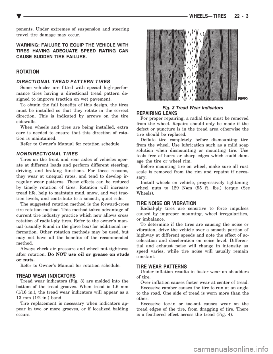
Tread wear indicators (Fig. 3) are molded into the
bottom of the tread grooves. When tread is 1.6 mm
(1/16 in.), the tread wear indicators will appear as a
13 mm (1/2 in.) band. Tire replacement is necessary when indicators ap-
pear in two or more grooves, or if localized balding
occurs.
REPAIRING LEAKS
For proper repairing, a radial tire must be removed
from the wheel. Repairs should only be made if the
defect or puncture is in the tread area otherwise the
tire should be replaced. Deflate tire completely before dismounting tire
from the wheel. Use lubrication such as a mild soap
solution when dismounting or mounting tire. Use
tools free of burrs or sharp edges which could dam-
age the tire or wheel rim. Before mounting tire on wheel, make sure all rust
scale is removed from the rim and repaint if neces-
sary. Install wheels on vehicle, progressively tightening
wheel nuts to 129 N Im (95 ft. lbs.) torque (See
Wheels).
TIRE NOISE OR VIBRATION
Radial-ply tires are sensitive to force impulses
caused by improper mounting, wheel irregularities,
or imbalance. To determine if the tires are causing the noise or
vibration, drive the vehicle over a smooth portion of
highway at different speeds and note the effect of ac-
celeration and deceleration on noise level. Differen-
tial and exhaust noise will change in intensity as
speed varies, while tire noise will usually remain
constant.
TIRE WEAR PATTERNS
Under inflation results in faster wear on shoulders
of tire. Over inflation causes faster wear at center of tread.
Excessive camber causes the tire to run at an angle
to the road. One side of tread is worn more than the
other. Excessive toe-in or toe-out causes wear on the
tread edges of the tire, from dragging of tire. There
is a feathered effect across the tread (Fig. 4).
Fig. 3 Tread Wear Indicators
Ä WHEELSÐTIRES 22 - 3
Page 2307 of 2438
SAFETY PRECAUTIONS AND WARNINGS
WARNING: WEAR EYE PROTECTION WHEN SER-
VICING THE AIR CONDITIONING REFRIGERANT
SYSTEM. SERIOUS EYE INJURY CAN RESULT
FROM EYE CONTACT WITH REFRIGERANT. IF EYE
CONTACT IS MADE, SEEK MEDICAL ATTENTION
IMMEDIATELY. DO NOT EXPOSE REFRIGERANT TO OPEN
FLAME. POISONOUS GAS IS CREATED WHEN RE-
FRIGERANT IS BURNED. AN ELECTRONIC TYPE
LEAK DETECTOR IS RECOMMENDED. LARGE AMOUNTS OF REFRIGERANT RELEASED
IN A CLOSED WORK AREA WILL DISPLACE THE
OXYGEN AND CAUSE SUFFOCATION. THE EVAPORATION RATE OF (R-12) REFRIGER-
ANT AT AVERAGE TEMPERATURE AND ALTITUDE
IS EXTREMELY HIGH. AS A RESULT, ANYTHING
THAT COMES IN CONTACT WITH THE REFRIGER-
ANT WILL FREEZE. ALWAYS PROTECT SKIN OR
DELICATE OBJECTS FROM DIRECT CONTACT
WITH REFRIGERANT.
CAUTION: Liquid refrigerant is corrosive to metal
surfaces. Follow the operating instructions supplied
with equipment being used.
COOLING SYSTEM PRECAUTIONS
WARNING: ANTIFREEZE IS AN ETHYLENE GLYCOL
BASE COOLANT AND IS HARMFUL IF SWAL-
LOWED OR INHALED. IF SWALLOWED, DRINK
TWO GLASSES OF WATER AND INDUCE VOMIT-
ING. IF INHALED, MOVE TO FRESH AIR AREA.
SEEK MEDICAL ATTENTION IMMEDIATELY. DO NOT STORE IN OPEN OR UNMARKED CON-
TAINERS. WASH SKIN AND CLOTHING THOROUGHLY AF-
TER COMING IN CONTACT WITH ETHYLENE GLY-
COL. KEEP OUT OF REACH OF CHILDREN AND PETS.
DO NOT OPEN A COOLING SYSTEM WHEN THE
ENGINE IS AT RUNNING TEMPERATURE. PER-
SONAL INJURY CAN RESULT.
The engine cooling system is designed to develop
internal pressure of 97 to 123 kPa (14 to 18 psi). Al-
low the vehicle 15 minutes (or until a safe tempera-
ture and pressure are attained) before opening the
cooling system. Refer to Group 7, Cooling System.
HANDLING TUBING AND FITTINGS
Kinks in the refrigerant tubing or sharp bends in
the refrigerant hose lines will greatly reduce the ca-
pacity of the entire system. High pressures are pro-
duced in the system when it is operating. Extreme
care must be exercised to make sure that all connec-
tions are pressure tight. Dirt and moisture can enter
the system when it is opened for repair or replace-
ment of lines or components. The refrigerant oil will
absorb moisture readily out of the air. This moisture
will convert into acids within a closed system. The following precautions must be observed:
The system must be completely empty before open-
ing any fitting or connection in the refrigeration sys-
tem. Open fittings with caution even after the
system has been emptied. If any pressure is noticed
as a fitting is loosened, allow trapped pressure to
bleed off very slowly. A good rule for the flexible hose lines is to keep the
radius of all bends at least 10 times the diameter of
the hose. Sharper bends will reduce the flow of re-
frigerant. The flexible hose lines should be routed so
they are at least 3 inches (80 mm) from the exhaust
manifold. Inspect all flexible hose lines to make sure
they are in good condition and properly routed. Unified plumbing connections with aluminum gas-
kets cannot be serviced with O-rings. These gaskets
are not reusable and do not require lubrication be-
fore installing. The use of correct wrenches when making connec-
tions is very important. Improper wrenches or im-
proper use of wrenches can damage the fittings. The A/C system will remain chemical stabile as
long as pure-moisture-free R-12 and refrigerant oil is
used. Abnormal amounts of dirt, moisture or air can
upset the chemical stability. This condition could
cause operational troubles or even serious damage if
present in more than very small quantities. When it is necessary to open the refrigeration sys-
tem, have everything needed to service the system
ready. The system should not be left open any longer
than necessary. Cap or plug all lines and fittings as
soon as they are opened to prevent the entrance or
dirt and moisture. All lines and components in parts
stock should be capped or sealed until they are ready
to be used. All tools, including the refrigerant dispensing man-
ifold, the manifold gauge set, and test hoses should
be kept clean and dry.
Fig. 6 Heater only or HeaterÐA/C Controls
Ä HEATING AND AIR CONDITIONING 24 - 3
Page 2312 of 2438
REFRIGERANT SERVICE PROCEDURES INDEX
page page
Adding Partial Refrigerant Charge ............ 10
Charging Refrigerant SystemÐEmpty System . . . 11
Discharging Refrigerant System .............. 11
Evacuating Refrigerant System .............. 11
Manifold Gauge Set Connections ............. 9 Oil Level
............................... 12
R-12 Refrigerant Equipment ................. 8
Refrigerant Recycling ...................... 9
Sight Glass Refrigerant Level Inspection ........ 8
Testing for Refrigerant Leaks ............... 10
SIGHT GLASS REFRIGERANT LEVEL INSPECTION
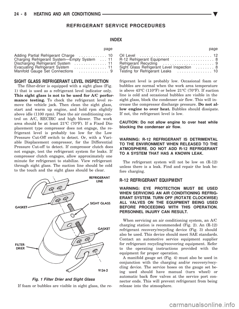
The filter-drier is equipped with a sight glass (Fig.
1) that is used as a refrigerant level indicator only.
This sight glass is not to be used for A/C perfor-
mance testing. To check the refrigerant level re-
move the vehicle jack. Then clean the sight glass,
start and warm up engine, and hold rpm slightly
above idle (1100 rpm). Place the air conditioning con-
trol on A/C, RECIRC and high blower. The work
area should be at least 21ÉC (70ÉF). If a Fixed Dis-
placement type compressor does not engage, the re-
frigerant level is probably too low for the Low
Pressure Cut-Off switch to detect. Or, with a Vari-
able Displacement compressor, for the Differential
Pressure Cut-off to detect. If compressor clutch does
not engage, test the refrigerant system for leaks. If
compressor clutch engages, allow approximately one
minute for refrigerant to stabilize. View refrigerant
through sight glass. The suction line should be cold
to the touch and the sight glass should be clear.
If foam or bubbles are visible in sight glass, the re- frigerant level is probably low. Occasional foam or
bubbles are normal when the work area temperature
is above 43ÉC (110ÉF) or below 21ÉC (70ÉF). If suction
line is cold and occasional bubbles are visible in the
sight glass, block the condenser air flow. This will in-
crease the compressor discharge pressure. Do not al-
low engine to over heat. Bubbles should dissipate.
If not, the refrigerant level is low.
CAUTION: Do not allow engine to over heat while
blocking the condenser air flow.
WARNING: R-12 REFRIGERANT IS DETRIMENTAL
TO THE ENVIRONMENT WHEN RELEASED TO THE
ATMOSPHERE. DO NOT ADD R-12 REFRIGERANT
TO A SYSTEM THAT HAS A KNOWN LEAK.
The refrigerant system will not be low on (R-12)
unless there is a leak. Find and repair the leak be-
fore charging.
R-12 REFRIGERANT EQUIPMENT
WARNING: EYE PROTECTION MUST BE USED
WHEN SERVICING AN AIR CONDITIONING REFRIG-
ERANT SYSTEM. TURN OFF (ROTATE CLOCKWISE)
ALL VALVES ON THE EQUIPMENT BEING USED
BEFORE PROCEEDING WITH THIS OPERATION.
PERSONNEL INJURY CAN RESULT.
When servicing an air conditioning system, an A/C
charging station is recommended (Fig. 2). An (R-12)
refrigerant recovery/recycling device (Fig. 3) should
also be used. This device should meet SAE standards.
Contact an automotive service equipment supplier
for refrigerant recycling/recovering equipment. Refer
to the operating instructions provided with the
equipment for proper operation. A manifold gauge set (Fig. 4) must also be used in
conjunction with the charging and/or recovery/recy-
cling device. The service hoses on the gauge set be-
ing used should have manual (turn wheel) or
automatic back flow valves at the service port con-
nector ends. This will prevent refrigerant from being
release into the atmosphere.
Fig. 1 Filter Drier and Sight Glass
24 - 8 HEATING AND AIR CONDITIONING Ä