1993 CHEVROLET PLYMOUTH ACCLAIM relay
[x] Cancel search: relayPage 124 of 2438

lighted monitor lamp will indicate a system failure.
Such as the exhaust solenoid operated for 120 610
seconds but the height sensor did not move to the
low position. See Diagnostic Chart 4. (5) The compressor relay output is activated to re-
turn the vehicle to the neutral (leveled) position. The
maximum operation time of the relay output is 150
6 10 seconds. If the expected position is not obtained.
The control module ceases self-diagnostics and any
further operation. The monitor lamp is continuously
lighted until the ignition is cycled from OFF to ON
or 60 61 minutes has elapsed after ignition is turned
off. The sensor will move to the neutral position. If not,
a continuously lighted monitor lamp will indicate a system failure. Such as the compressor relay output
operated for 150 610 seconds but the sensor did not
move to or sense the neutral position. See Diagnostic
Chart 1. (6) Completion of diagnostics, is when self diagnostic
procedure is successfully completed and control module
resumes normal operation. The diagnostic test is now
complete. Throughout the testing the vehicle load must
be maintained at a specific level. No loads are allowed
to be added/removed to/from the vehicle once the self
diagnosis tests have been initiated. The Diagnostic connector cover must be in-
stalled after completion of the test.
2 - 66 SUSPENSION AND DRIVESHAFTS Ä
Page 130 of 2438

CONTROL MODULE
REMOVAL
(1) Disconnect negative battery cable.
(2) Remove right side trunk trim panel.
(3) Remove electrical connectors from control mod-
ule and relay (Fig. 9). (4) Remove control module mounting screws and
remove assembly.
INSTALLATION
(1) Install relay on the control module mounting
bracket (if required). (2) Place control module in mounting position.
(3) Install mounting screws and tighten to 2-3 N Im
(19-29 in. lbs.). (4) Install control module and relay wiring connec-
tors (Fig. 9). (5) Install right side trunk trim panel.
(6) Connect negative battery cable.
COMPRESSOR RELAY
REMOVAL
(1) Remove right side trunk trim panel.
(2) Remove electrical connector from relay.
(3) Remove relay from control module mounting
bracket by prying out on locating clip (Fig. 10).
INSTALLATION
(1) Push relay onto bracket (relay will Lock into
position). (2) Install electrical connector.
(3) Install trim panel.
RIGHT SHOCK ABSORBER (WITH HEIGHT
SENSOR)
REMOVAL
(1) Disconnect negative battery cable.
(2) Raise vehicle, see Hoisting, Group 0.
(3) Remove tire assembly.
(4) Disconnect height sensor connector, located on
right rear frame rail. (5) Remove both air lines connected to shock ab-
sorber ports. (6) Remove shock, see Shock Absorbers, Removal.
INSTALLATION
(1) Install shock assembly, see Shock Absorbers,
Installation. (2) Route height sensor wire through clip on shock
bracket, then tie strap to fuel filler tube. (3) Snap height sensor connector into underbody
harness connector. (4) Insert air lines.
(5) Install wheel/tire assembly.
Fig. 9 Control Module and Relay Wiring
Fig. 10 Control Module Connector
2 - 72 SUSPENSION AND DRIVESHAFTS Ä
Page 131 of 2438

AUTOMATIC AIR SUSPENSION INDEX
page page
Air Lines ............................... 75
Air Springs Rear ......................... 87
Compressor Performance Test .............. 77
Diagnosis .............................. 78
General Information ....................... 73
Recharge Air Spring ...................... 87 Right Shock Absorber (With Height Sensor)
.... 88
Safety Concerns ......................... 78
Service Procedures ....................... 85
Shipping Mode .......................... 78
Solenoids (Struts and Air Springs) ............ 86
System Operation ........................ 78
GENERAL INFORMATION
This system provides automatic height control and
low spring rates to improve suspension characteristics
of the vehicle. And it will automatically level the front
and rear of the vehicle. It will also maintain the opti-
mum vehicle attitude from one passenger through full
vehicle load.
The automatic air suspension system includes the
following components:
² Compressor/air dryer assembly
² Compressor relay
² Front struts
² Rear springs
² Rear shocks
² Control module
² Air lines ²
Compressor
² Rear height sensor
² Wiring harness assembly
² Compressor cover
Front springs (and height sensors) are integral with
the shock absorber strut assemblies. While rear air
springs replace conventional steel units. Rear height is
controlled via a height sensor contained within the
right rear shock absorber. Solenoids (integral with each
air spring) control air volume/pressure requirements.
Pressurized air is distributed from the air compressor/
dryer assembly and routed to each air spring by four
separate air lines. The air lines start at the dryer and
terminate at the individual air springs. The system is
monitored and controlled by the Air Suspension Control
Module (ASCM) (Fig. 1).
Fig. 1 Automatic Air Suspension
Ä SUSPENSION AND DRIVESHAFTS 2 - 73
Page 132 of 2438

FRONT AND REAR AIR SPRINGS
The front and rear air springs are essentially pneu-
matic cylinders that replace the steel coil springs.
The air filled springs allow the vehicle suspension
height to be adjusted for all weight conditions. The air springs allow for the reduction of spring
rates to improve vehicle ride characteristics.
FRONT/REAR SPRING SOLENOIDS
The front and rear solenoids control air flow in and
out of the front and rear springs. The Air Suspension
Control Module (ASCM) opens the solenoids when
the system requires air to be added to or exhausted
from the air springs. The solenoids operate at a cur-
rent draw range of 0.6 to 1.5 amps.
HEIGHT SENSOR
A magnetic switch type sensor. Located in the
right rear shock absorber and left and right front
struts, (Fig. 2) monitors vehicle height. The sensors
transmit signals to the (ASCM) relating to vehicle
height status (low, trim, medium, high).
CONTROL MODULE
The Air Suspension Control Module (ASCM). Is a
device that controls the ground circuits for the Com-
pressor Relay, Compressor Exhaust Solenoid Valve
and Front and Rear Solenoid Valves. The (ASCM)
limits the compressor pump operation time to 170 to
190 seconds. This controlled operation time is to pre- vent damage to the compressor motor.
To prevent excessive cycling between the compres-
sor and the exhaust solenoid circuits during normal
ride conditions. A 14 to 16 second delay is incorpo-
rated in the microprocessor logic. The system is non-operation when one of the fol-
lowing conditions exists. A door(s) is/are open, the
trunk is open, the service brake is applied or the
throttle position sensor is 65% to 100% open. System
operation is inhibited during high speed cornering
activities or if there is a charging system failure.
The control module is on the CCD bus system.
COMPRESSOR ASSEMBLY
The compressor assembly is driven by an electric
motor and supplies air pressure between 930 to 1241
kPa (135 to 180 psi) (Fig. 3). A solenoid operated ex-
haust valve. Located in the compressor head assem-
bly, releases air when energized. A heat actuated circuit breaker. Located inside the
compressor motor housing. Is used to prevent damage
to the compressor motor in case of control module
failure.
COMPRESSOR AIR DRYER
The air dryer is attached to the compressor (Fig. 3).
This component serves two purposes. It absorbs mois-
ture from the atmosphere before it enters the system
Fig. 2 Front and Rear Air Springs
2 - 74 SUSPENSION AND DRIVESHAFTS Ä
Page 143 of 2438

SERVICE PROCEDURES
CONTROL MODULE (ASCM)
REMOVAL (1) Disconnect negative battery cable.
(2) Remove right side trunk trim panel.
(3) Remove electrical connectors from control mod-
ule and relay (Fig. 11). (4) Remove control module mounting screws and
remove assembly.
INSTALLATION
(1) Install relay on the control module mounting
bracket (if required). (2) Place control module in mounting position.
(3) Install mounting screws and tighten to 2-3 N Im
(19-29 in. lbs.) torque. (4) Install control module and relay wiring connec-
tors (Fig. 11). (5) Install right side trunk trim panel.
(6) Connect negative battery cable.
COMPRESSOR RELAY
REMOVAL
(1) Remove right side trunk trim panel.
(2) Remove electrical connector from relay.
(3) Remove relay from control module mounting
bracket by prying out on locating clip (Fig. 11)
INSTALLATION (1) Push relay onto bracket (relay will Lock into
position.) (2) Install electrical connector. (3) Install trim panel.
COMPRESSOR ASSEMBLY
REMOVAL
(1) Disconnect battery negative cable.
(2) Raise vehicle, see Hoisting, Group 0.
(3) Remove cover from compressor assembly. Re-
move air hose (see AIR LINES) and electrical connec-
tors (Fig. 12) (4) Remove compressor assembly mounting screws
and lower assembly from vehicle. (5) Remove mounting bracket screws and slide
mounting bracket away from compressor.
INSTALLATION (1) Slide mounting bracket on compressor and in-
stall screws and tighten to 8 N Im (70 in. lbs.) torque.
DO NOT OVER TORQUE THESE SCREWS. (2) Install compressor assembly to frame rail and
tighten screws to 8 N Im (70 in. lbs.) torque. DO NOT
OVER TORQUE THESE SCREWS. (3) Connect air hose and electrical connector to com-
pressor assembly. (4) Install cover on compressor assembly and tighten
screws to 6 N Im (40 in. lbs.) torque.
(5) Lower vehicle and connect battery negative
cable. (6) Check operation of the system.
AIR DRYER
REMOVAL
Remove compressor assembly. See COMPRESSOR
ASSEMBLY.
Fig. 11 Control Module and Relay Wiring
Fig. 12 Compressor Assembly
Ä SUSPENSION AND DRIVESHAFTS 2 - 85
Page 222 of 2438

ANTI-LOCK BRAKE SYSTEMÐBENDIX ANTI-LOCK 10 AC/Y BODY INDEX
page page
ABS Brake System Diagnostic Features ....... 92
ABS Braking System Diagnosis .............. 87
ABS Controller Anti-Lock Brake (CAB) Service Precautions ........................... 88
ABS Equipped Vehicle Performance .......... 75
ABS Hydraulic Circuits and Valve Operation .... 85
ABS System Diagnostic Connector ........... 82
ABS System General Service Precautions ...... 88
ABS System Self-Diagnostics ............... 75
ABS Warning Systems Operation ............ 75
Anti-Lock Brake System Components ......... 76 Anti-Lock Brake System Definitions
........... 72
Anti-Lock Operation and Performance ......... 73
Anti-Lock System Relays and Warning Lamps . . . 82
Controller Anti-Lock Brake (CAB) ............. 80
Electronic Components ................... 103
General Information ....................... 72
General Service Precautions ................ 93
Major ABS Components ................... 73
Mechanical Diagnostics and Service Procedures . 89
Normal Braking System Function ............. 72
On Car Hydraulic ABS Component Service ..... 93
GENERAL INFORMATION
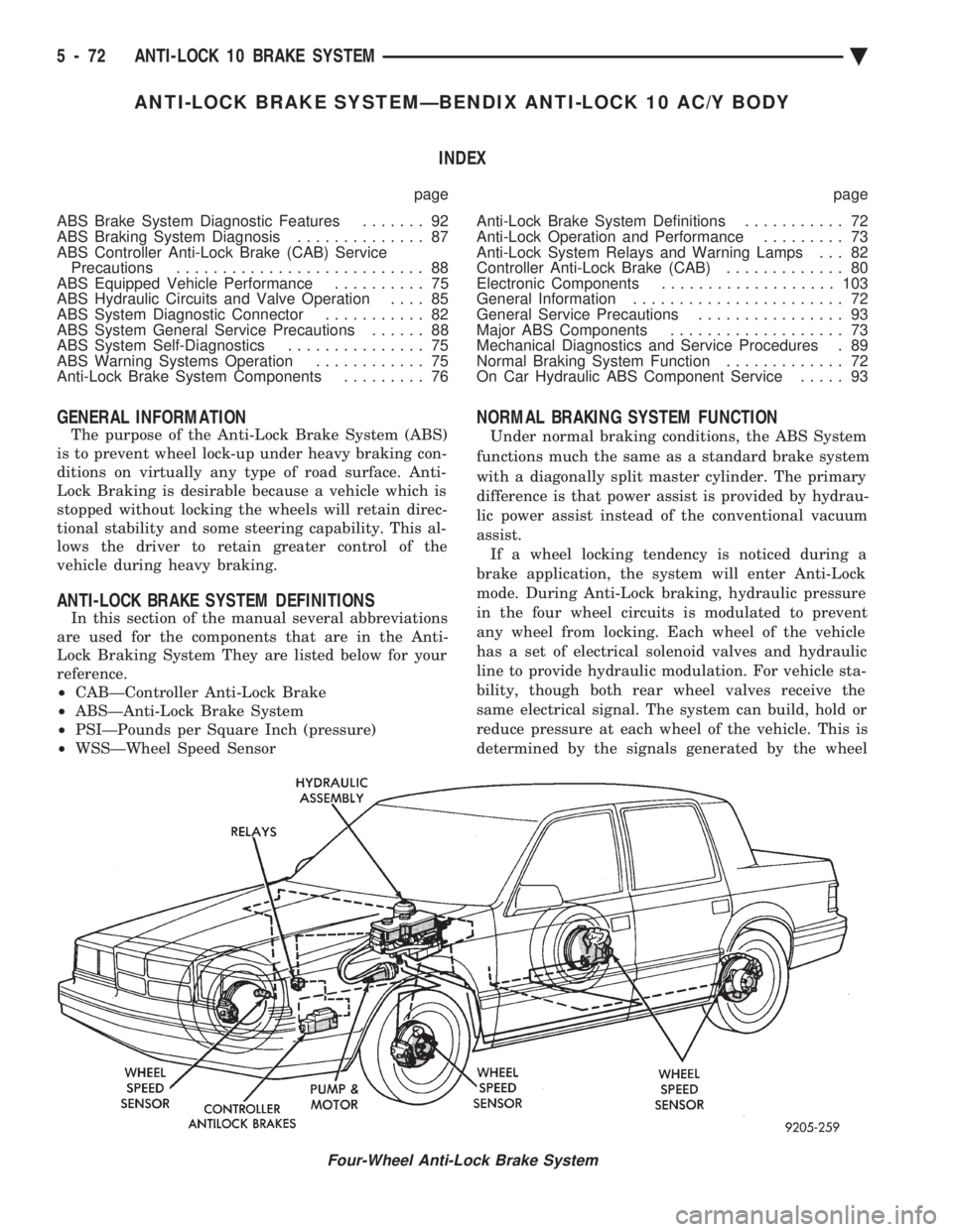
The purpose of the Anti-Lock Brake System (ABS)
is to prevent wheel lock-up under heavy braking con-
ditions on virtually any type of road surface. Anti-
Lock Braking is desirable because a vehicle which is
stopped without locking the wheels will retain direc-
tional stability and some steering capability. This al-
lows the driver to retain greater control of the
vehicle during heavy braking.
ANTI-LOCK BRAKE SYSTEM DEFINITIONS
In this section of the manual several abbreviations
are used for the components that are in the Anti-
Lock Braking System They are listed below for your
reference.
² CABÐController Anti-Lock Brake
² ABSÐAnti-Lock Brake System
² PSIÐPounds per Square Inch (pressure)
² WSSÐWheel Speed Sensor
NORMAL BRAKING SYSTEM FUNCTION
Under normal braking conditions, the ABS System
functions much the same as a standard brake system
with a diagonally split master cylinder. The primary
difference is that power assist is provided by hydrau-
lic power assist instead of the conventional vacuum
assist. If a wheel locking tendency is noticed during a
brake application, the system will enter Anti-Lock
mode. During Anti-Lock braking, hydraulic pressure
in the four wheel circuits is modulated to prevent
any wheel from locking. Each wheel of the vehicle
has a set of electrical solenoid valves and hydraulic
line to provide hydraulic modulation. For vehicle sta-
bility, though both rear wheel valves receive the
same electrical signal. The system can build, hold or
reduce pressure at each wheel of the vehicle. This is
determined by the signals generated by the wheel
Four-Wheel Anti-Lock Brake System
5 - 72 ANTI-LOCK 10 BRAKE SYSTEM Ä
Page 227 of 2438

circuits are hydraulically isolated so a leak or mal-
function in one circuit will allow continued braking
ability in the other.When force is applied to the brake pedal, the input
pushrod applies force to the boost control valve. As
the boost control valve is moved, it allows the pres-
surized fluid from the accumulator to flow into the
master cylinder booster chamber. The pressure gen-
erated in the booster chamber is directly propor-
tioned to the brake pedal force exerted by the driver.
This pressure in the booster servo in turn applies
pressure to the primary master cylinder piston that
in turn applies pressure to the secondary master cyl-
inder piston. The pressure generated in the primary
and secondary circuits are used to apply the brakes
during normal braking.
WARNING: THE HYDRAULIC ACCUMULATORS
CONTAIN BRAKE FLUID AND NITROGEN GAS AT
HIGH PRESSURE. CERTAIN PORTIONS OF THE
BRAKE SYSTEM ALSO CONTAIN BRAKE FLUID AT
HIGH PRESSURE. REMOVAL OR DISASSEMBLY
MAY RESULT IN PERSONAL INJURY AND IM-
PROPER SYSTEM OPERATION. REFER TO THE AP-
PROPRIATE SERVICE MANUAL FOR PROPER
SERVICE PROCEDURES.
HYDRAULIC BLADDER ACCUMULATOR
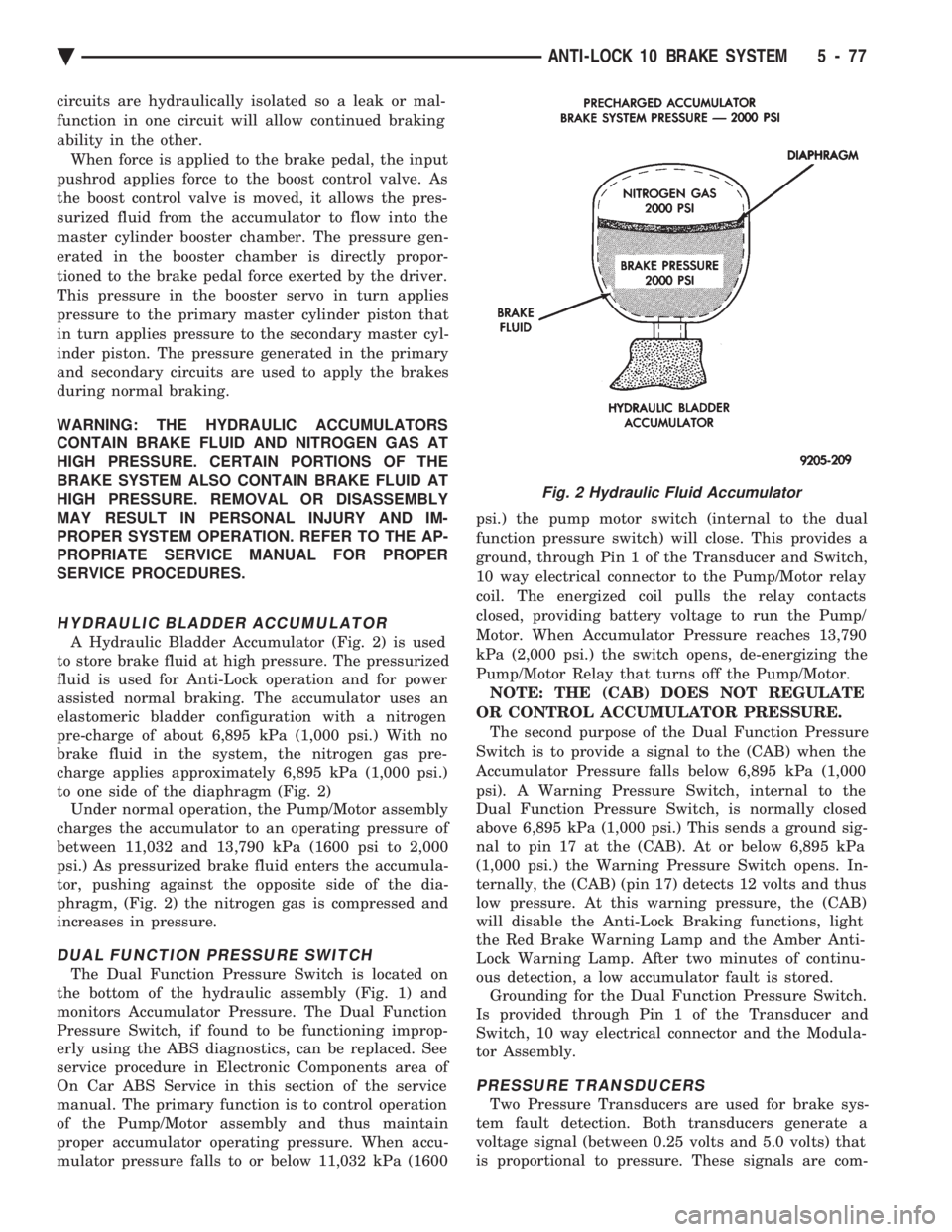
A Hydraulic Bladder Accumulator (Fig. 2) is used
to store brake fluid at high pressure. The pressurized
fluid is used for Anti-Lock operation and for power
assisted normal braking. The accumulator uses an
elastomeric bladder configuration with a nitrogen
pre-charge of about 6,895 kPa (1,000 psi.) With no
brake fluid in the system, the nitrogen gas pre-
charge applies approximately 6,895 kPa (1,000 psi.)
to one side of the diaphragm (Fig. 2) Under normal operation, the Pump/Motor assembly
charges the accumulator to an operating pressure of
between 11,032 and 13,790 kPa (1600 psi to 2,000
psi.) As pressurized brake fluid enters the accumula-
tor, pushing against the opposite side of the dia-
phragm, (Fig. 2) the nitrogen gas is compressed and
increases in pressure.
DUAL FUNCTION PRESSURE SWITCH
The Dual Function Pressure Switch is located on
the bottom of the hydraulic assembly (Fig. 1) and
monitors Accumulator Pressure. The Dual Function
Pressure Switch, if found to be functioning improp-
erly using the ABS diagnostics, can be replaced. See
service procedure in Electronic Components area of
On Car ABS Service in this section of the service
manual. The primary function is to control operation
of the Pump/Motor assembly and thus maintain
proper accumulator operating pressure. When accu-
mulator pressure falls to or below 11,032 kPa (1600 psi.) the pump motor switch (internal to the dual
function pressure switch) will close. This provides a
ground, through Pin 1 of the Transducer and Switch,
10 way electrical connector to the Pump/Motor relay
coil. The energized coil pulls the relay contacts
closed, providing battery voltage to run the Pump/
Motor. When Accumulator Pressure reaches 13,790
kPa (2,000 psi.) the switch opens, de-energizing the
Pump/Motor Relay that turns off the Pump/Motor. NOTE: THE (CAB) DOES NOT REGULATE
OR CONTROL ACCUMULATOR PRESSURE. The second purpose of the Dual Function Pressure
Switch is to provide a signal to the (CAB) when the
Accumulator Pressure falls below 6,895 kPa (1,000
psi). A Warning Pressure Switch, internal to the
Dual Function Pressure Switch, is normally closed
above 6,895 kPa (1,000 psi.) This sends a ground sig-
nal to pin 17 at the (CAB). At or below 6,895 kPa
(1,000 psi.) the Warning Pressure Switch opens. In-
ternally, the (CAB) (pin 17) detects 12 volts and thus
low pressure. At this warning pressure, the (CAB)
will disable the Anti-Lock Braking functions, light
the Red Brake Warning Lamp and the Amber Anti-
Lock Warning Lamp. After two minutes of continu-
ous detection, a low accumulator fault is stored. Grounding for the Dual Function Pressure Switch.
Is provided through Pin 1 of the Transducer and
Switch, 10 way electrical connector and the Modula-
tor Assembly.
PRESSURE TRANSDUCERS
Two Pressure Transducers are used for brake sys-
tem fault detection. Both transducers generate a
voltage signal (between 0.25 volts and 5.0 volts) that
is proportional to pressure. These signals are com-
Fig. 2 Hydraulic Fluid Accumulator
Ä ANTI-LOCK 10 BRAKE SYSTEM 5 - 77
Page 229 of 2438

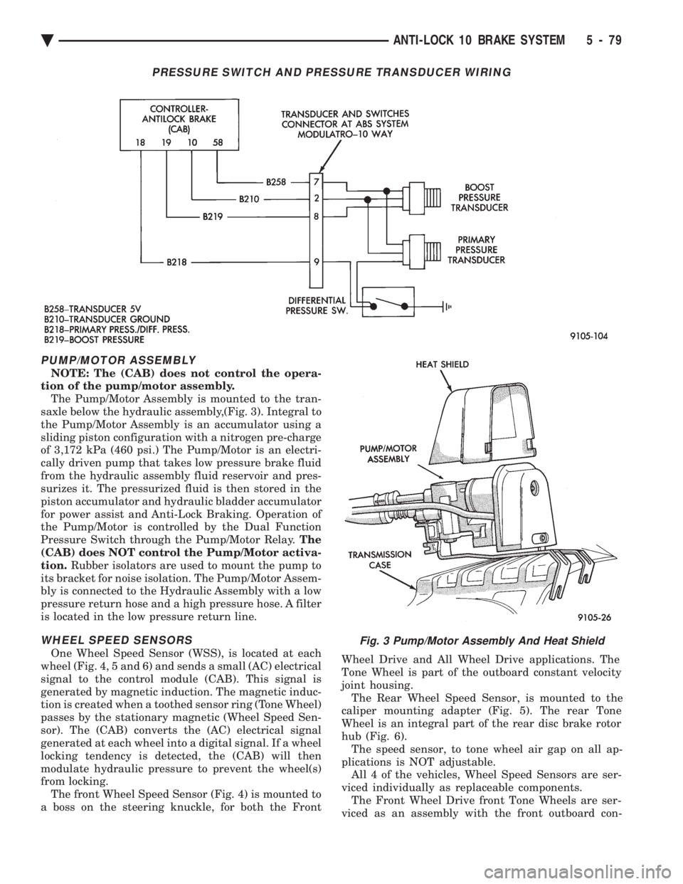
PUMP/MOTOR ASSEMBLY
NOTE: The (CAB) does not control the opera-
tion of the pump/motor assembly. The Pump/Motor Assembly is mounted to the tran-
saxle below the hydraulic assembly,(Fig. 3). Integral to
the Pump/Motor Assembly is an accumulator using a
sliding piston configuration with a nitrogen pre-charge
of 3,172 kPa (460 psi.) The Pump/Motor is an electri-
cally driven pump that takes low pressure brake fluid
from the hydraulic assembly fluid reservoir and pres-
surizes it. The pressurized fluid is then stored in the
piston accumulator and hydraulic bladder accumulator
for power assist and Anti-Lock Braking. Operation of
the Pump/Motor is controlled by the Dual Function
Pressure Switch through the Pump/Motor Relay. The
(CAB) does NOT control the Pump/Motor activa-
tion. Rubber isolators are used to mount the pump to
its bracket for noise isolation. The Pump/Motor Assem-
bly is connected to the Hydraulic Assembly with a low
pressure return hose and a high pressure hose. A filter
is located in the low pressure return line.
WHEEL SPEED SENSORS
One Wheel Speed Sensor (WSS), is located at each
wheel (Fig. 4, 5 and 6) and sends a small (AC) electrical
signal to the control module (CAB). This signal is
generated by magnetic induction. The magnetic induc-
tion is created when a toothed sensor ring (Tone Wheel)
passes by the stationary magnetic (Wheel Speed Sen-
sor). The (CAB) converts the (AC) electrical signal
generated at each wheel into a digital signal. If a wheel
locking tendency is detected, the (CAB) will then
modulate hydraulic pressure to prevent the wheel(s)
from locking. The front Wheel Speed Sensor (Fig. 4) is mounted to
a boss on the steering knuckle, for both the Front Wheel Drive and All Wheel Drive applications. The
Tone Wheel is part of the outboard constant velocity
joint housing. The Rear Wheel Speed Sensor, is mounted to the
caliper mounting adapter (Fig. 5). The rear Tone
Wheel is an integral part of the rear disc brake rotor
hub (Fig. 6). The speed sensor, to tone wheel air gap on all ap-
plications is NOT adjustable. All 4 of the vehicles, Wheel Speed Sensors are ser-
viced individually as replaceable components. The Front Wheel Drive front Tone Wheels are ser-
viced as an assembly with the front outboard con-
Fig. 3 Pump/Motor Assembly And Heat Shield
PRESSURE SWITCH AND PRESSURE TRANSDUCER WIRING
Ä ANTI-LOCK 10 BRAKE SYSTEM 5 - 79