1993 CHEVROLET PLYMOUTH ACCLAIM air conditioning
[x] Cancel search: air conditioningPage 366 of 2438

ACCESSORY DRIVE BELTS INDEX
page page
2.2/2.5L Engine Belts Remove/Install-Adjust .... 24
3.0L Engine Belts Remove/Install and Adjust .... 25
3.3/3.8L and Turbo III Engine Accessory Drive Belt Remove and Install
..................... 26
General Information ....................... 24
GENERAL INFORMATION
PROPER BELT TENSION
Satisfactory performance of the belt driven accesso-
ries depends on belt condition (Fig. 1) and proper belt
tension. Two tensioning methods are given in order
of preference:
² Belt tension gauge method.
² Torque equivalent method.
The belt tension gauge method is usually restricted
to use after the vehicle has been raised on a hoist
and the splash shield has been removed.
BELT TENSION GAUGE METHOD Use belt tensioning Special Tool Kit C-4162 for:
² For conventional belts and Poly-V belts.
Adjust the belt tension for a NeworUsed belt as
prescribed in the Belt Tension Chart.
TORQUE EQUIVALENT METHOD Adjustable accessory brackets provided with a
13mm (1/2 in.) square hole for a torque wrench can
use an equivalent torque value for belt adjustment. Equivalent torque values for adjusting these acces-
sory drive belts are specified on the Belt Tension
Charts .
2.2/2.5L ENGINE BELTS REMOVE/INSTALL-
ADJUST
AIR CONDITIONING COMPRESSOR
(1) Loosen the idler bracket pivot screw A and
locking screws B (Fig. 2) to remove and install belt
and/or adjust belt tension.
ACCESSORY DRIVE BELTS DIAGNOSIS
Fig. 1 Drive Belt Inspection
7 - 24 COOLING SYSTEM Ä
Page 367 of 2438

(2) Adjust belt tension by applying torque to
square hole C on idler bracket. Adjust tension to
specification given in Belt Tension Chart. (3) Tighten in order, first, locking screws B then
pivot screw A to 54 N Im (40 ft. lbs.).
POWER STEERING PUMPÐS TYPE
(1) From on top of the vehicle loosen locking screw G.
(2) From under the vehicle loosen the pivot screw
and pivot nut H . (3) After installing a new belt adjust belt tension
with 1/2 in. breaker bar installed in adjusting
bracket. See tension specification in chart. (4) Tighten locking screw G to 54 N Im (40 ft. lbs.).
(5) Tighten pivot screw H and the pivot nut to 54
N Im (40 ft. lbs.)
GENERATOR BELT
(1) Loosen T-Bolt locking nut E and adjusting
screw F to remove and install Poly V belt and/or ad-
just belt tension. (2) Tighten adjusting screw F to adjust belt tension
to specification shown in Belt Tension Chart. (3) Tighten T-Bolt locking nut E to 54 N Im (40 ft.
lbs.).
3.0L ENGINE BELTS REMOVE/INSTALL AND
ADJUST
AIR CONDITIONING BELT
To remove and install the air conditioning com-
pressor drive belt, first loosen the idler pulley lock
nut, then turn the adjusting screw to raise or lower
the idler pulley (Figs. 3 and 4).
To adjust the air conditioning drive belt, loosen
the idler pulley nut (Fig. 3) and adjust belt tension
Fig. 2 Accessory Drive BeltsÐ2.2 and 2.5L Engines
Fig. 3 Accessory Drive BeltsÐ3.0L Engine
Ä COOLING SYSTEM 7 - 25
Page 368 of 2438

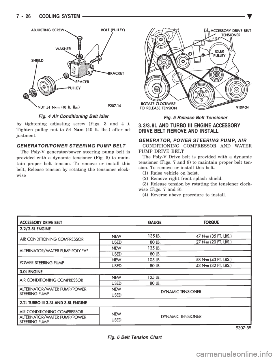
by tightening adjusting screw (Figs. 3 and 4 ).
Tighten pulley nut to 54 N Im (40 ft. lbs.) after ad-
justment.
GENERATOR/POWER STEERING PUMP BELT
The Poly-V generator/power steering pump belt is
provided with a dynamic tensioner (Fig. 5) to main-
tain proper belt tension. To remove or install this
belt, Release tension by rotating the tensioner clock-
wise
3.3/3.8L AND TURBO III ENGINE ACCESSORY
DRIVE BELT REMOVE AND INSTALL
GENERATOR, POWER STEERING PUMP, AIR
CONDITIONING COMPRESSOR AND WATER
PUMP DRIVE BELT The Poly-V Drive belt is provided with a dynamic
tensioner (Figs. 7 and 8) to maintain proper belt ten-
sion. To remove or install this belt. (1) Raise vehicle on hoist.
(2) Remove right front splash shield.
(3) Release tension by rotating the tensioner clock-
wise (Figs. 7 and 8). (4) Reverse above procedure to install.
Fig. 5 Release Belt Tensioner
Fig. 6 Belt Tension Chart
Fig. 4 Air Conditioning Belt Idler
7 - 26 COOLING SYSTEM Ä
Page 411 of 2438

GENERATOR INDEX
page page
General Information ........................ 9
Generator ReplacementÐ2.2L Turbo Engine (With 16 Valve Cylinder Head) ............. 10 Generator ReplacementÐ2.2L/2.5L Engine
...... 9
Generator ReplacementÐ3.0L Engine ......... 10
Generator ReplacementÐ3.3L/3.8L Engine ..... 11
GENERAL INFORMATION
This section will cover generator removal and instal-
lation only. Information covering generator on-vehicle
testing and diagnosis can be found in Group 8A,
Battery/Starting/Charging Systems Diagnostics. To
identify the generator, refer to the Generator Specifi-
cation chart at the rear of this section. These generators are not intended to be disas-
sembled for service. It must be replaced as an
assembly.
GENERATOR REPLACEMENTÐ2.2L/2.5L ENGINE
Removal and repositioning of A/C compressor (with-
out disconnecting refrigerant lines) is necessary on
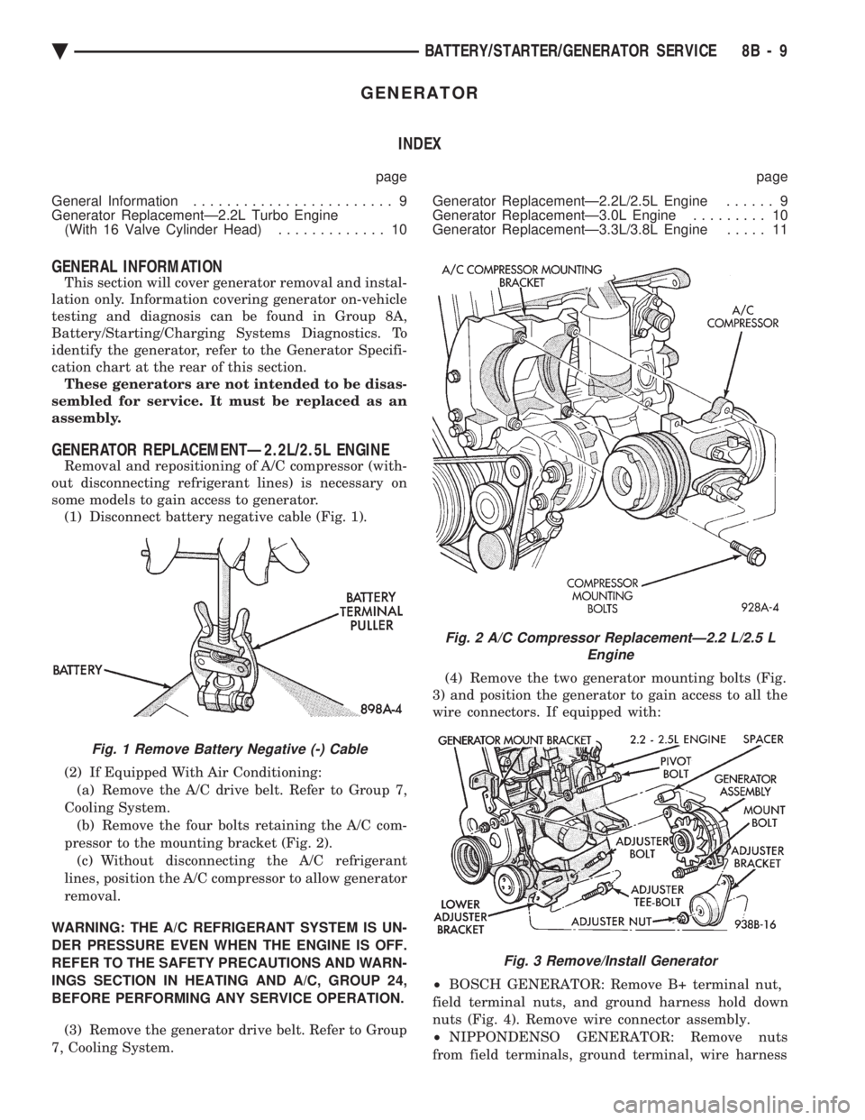
some models to gain access to generator. (1) Disconnect battery negative cable (Fig. 1).
(2) If Equipped With Air Conditioning:
(a) Remove the A/C drive belt. Refer to Group 7,
Cooling System. (b) Remove the four bolts retaining the A/C com-
pressor to the mounting bracket (Fig. 2). (c) Without disconnecting the A/C refrigerant
lines, position the A/C compressor to allow generator
removal.
WARNING: THE A/C REFRIGERANT SYSTEM IS UN-
DER PRESSURE EVEN WHEN THE ENGINE IS OFF.
REFER TO THE SAFETY PRECAUTIONS AND WARN-
INGS SECTION IN HEATING AND A/C, GROUP 24,
BEFORE PERFORMING ANY SERVICE OPERATION. (3) Remove the generator drive belt. Refer to Group
7, Cooling System. (4) Remove the two generator mounting bolts (Fig.
3) and position the generator to gain access to all the
wire connectors. If equipped with:
² BOSCH GENERATOR: Remove B+ terminal nut,
field terminal nuts, and ground harness hold down
nuts (Fig. 4). Remove wire connector assembly.
² NIPPONDENSO GENERATOR: Remove nuts
from field terminals, ground terminal, wire harness
Fig. 1 Remove Battery Negative (-) Cable
Fig. 2 A/C Compressor ReplacementÐ2.2 L/2.5 L Engine
Fig. 3 Remove/Install Generator
Ä BATTERY/STARTER/GENERATOR SERVICE 8B - 9
Page 412 of 2438

and B+ terminal (Fig. 5). B+ terminal nut must be
removed last to prevent damage to terminal insula-
tor. (5) Remove the generator from the vehicle.
(6) For installation, reverse above procedures.
Tighten all fasteners to the proper torque. Refer to
the Torque Specifications chart at the rear of this
group.
GENERATOR REPLACEMENTÐ2.2L TURBO
ENGINE (WITH 16 VALVE CYLINDER HEAD)
(1) Disconnect battery NEGATIVE cable (Fig. 1).
(2) Remove generator/air conditioning drive belt.
Refer to Group 7, Cooling System. (3) Remove the bolts retaining the A/C compressor
to the mounting bracket. (4) Without disconnecting the A/C refrigerant
lines, position the A/C compressor to allow generator
removal. WARNING: THE A/C REFRIGERANT SYSTEM IS UN-
DER PRESSURE EVEN WHEN THE ENGINE IS OFF.
REFER TO THE SAFETY PRECAUTIONS AND
WARNINGS SECTION IN HEATING AND A/C,
GROUP 24, BEFORE PERFORMING ANY SERVICE
OPERATION.
(5) Remove the generator mounting bracket bolts
and separate generator from mounting bracket (Fig.
6).
(6) Remove the B+ terminal nut, field terminal
nuts, and ground/wire harness hold-down nuts. Re-
move wire connectors. (7) Remove the generator from the vehicle.
(8) For installation, reverse above procedures.
Tighten all fasteners to the proper torque. Refer to
the Torque Specifications chart at the rear of this
group.
GENERATOR REPLACEMENTÐ3.0L ENGINE
(1) Disconnect battery negative cable (Fig. 1).
(2) Remove generator drive belt. Refer to Group 7,
Cooling System. (3) Remove the generator mounting bolts and sep-
arate the generator from the mounting bracket (Fig.
7). (4) Remove the B+ terminal nut, field terminal
nuts, and ground/wire harness hold-down nuts. Re-
move wire connectors. (5) Remove the generator from the vehicle.
Fig. 4 Remove or Install Wire Connector AssemblyÐBosch Generator
Fig. 5 Remove or Install Wire ConnectorAssemblyÐNippondenso Generator
Fig. 6 Generator MountingÐ2.2 L Turbo Engine With 16 Valve Cylinder Head
8B - 10 BATTERY/STARTER/GENERATOR SERVICE Ä
Page 513 of 2438

(3) Remove four screws from ash receiver/cup
holder housing. (4) For installation reverse above procedures.
AIR CONDITIONING CONTROLREPLACEMENT
(1) Disconnect battery negative cable and isolate
or remove fuse #2 prior to removing switch or wires
may short to ground. (2) Remove center bezel. Disconnect ash receiver
lamp socket. (3) Remove glove box assembly. Refer to Glove Box
Assembly Replacement. (4) Reach through glove box opening and discon-
nect vacuum lines. (5) Remove two control mounting screws (Fig. 50).
(6) Slide control rearward, disconnect cable, and
electrical wiring. (7) Remove unit.
(8) For installation reverse above procedures.
CIGAR LIGHTER ASSEMBLY REPLACEMENT
(1) Remove center bezel. Disconnect ash receiver
lamp socket. (2) Remove two screws from bezel of the lighter as-
sembly. (3) Pull assembly rearward and disconnect wiring.
(4) For installation reverse above procedures.
TRAVELER/MESSAGE CENTER REPLACEMENT
(1) Remove cluster bezel.
(2) Remove four mounting screws.
(3) Pull unit rearward and disconnect wiring.
(4) For installation reverse above procedures.
INSTRUMENT PANEL
INSTRUMENT PANEL TOP COVER REPLACEMENT
(1) Lift up rearward edge of instrument panel top
cover. (2) Pull panel rearward to remove.
(3) To install: position top cover and snap into
place, pull rearward for proper fit.
INSTRUMENT PANEL REPLACEMENT
CAUTION: Disconnect negative battery cable, in en-
gine compartment, before servicing instrument
panel.
(1) Disconnect battery negative cable and isolate
or remove fuse #2 prior to removing switch or wires
may short to ground. (2) Remove left and right A-pillar trim.
(3) Remove left and right cowl side trim.
(4) Remove glove box assembly. Refer to Glove Box
Assembly Replacement. (5) Remove four relays above glove box assembly.
(6) Reach through glove box opening and discon-
nect A/C control vacuum lines, radio noise suppressor
wires, and blower motor/cycling switch wires. (7) Remove hood release handle.
(8) Remove lower steering column cover.
(9) Remove lower left instrument panel silencer
and reinforcement. (10) Remove instrument panel center bezel.
(11) Remove floor console. Refer to Group 23,
Body. (12) Remove radio, A/C control, cigar lighter, and
message center/traveler. (13) Disconnect demister hoses.
(14) Remove instrument panel top cover (Fig. 51).
(15) Disconnect battery to assure no air bag sys-
tem fault codes are stored. (16) Remove cluster refer to Cluster Assembly.
(17) Remove radio and rear window defogger be-
zels. (18) Lower steering column.
(19) Loosen instrument panel pivot bolts.
(20) Remove screws which attach instrument panel
to windshield fence line. (21) Allow panel to roll down slightly and discon-
nect remaining electrical connections. (22) With the aid of a helper remove panel pivot
bolts and remove panel from vehicle. (23) For installation reverse above procedures.
INTERIOR LAMP REPLACEMENT
The dome, overhead console and door lamps, if
equipped operate when the doors are open or head-
lamp switch is placed in courtesy position. The front
header reading lamp operates only when the lamp
push buttons are ON.
DOME LAMP
Pry either the forward or rearward edge of the lens
away from the bezel and replace lamp.
FRONT HEADER READING LAMP
Pull lamp from headliner. Disconnect wiring and
replace lamp.
Fig. 50 A/C Control
Ä INSTRUMENT PANEL AND GAUGES 8E - 21
Page 529 of 2438

CONDITION: US/METRIC MODES WILL NOT TOGGLE OR TRIP ODOMETER WILL NOTRESET
PROCEDURE
(1) Perform cluster self-diagnostics to determine if
push buttons are operational. (2) Refer to the Body Chassis Diagnostic Manual
to diagnose CCD Bus. The US/Metric toggle and trip
odometer reset are activated over the CCD Bus.
ODOMETER ADJUSTMENT
The odometer memory is no longer retained in the
cluster. This information is stored in the body con-
troller. Therefore, there is no adjustment procedure.
If the cluster is replaced odometer value will not
change. If the body controller is replaced the mileage
may be transferred using the DRB II. Refer to the
Body Chassis Diagnostic Manual for the procedure.
SWITCH AND PANEL COMPONENT SERVICE
MESSAGE CENTER REPLACEMENT
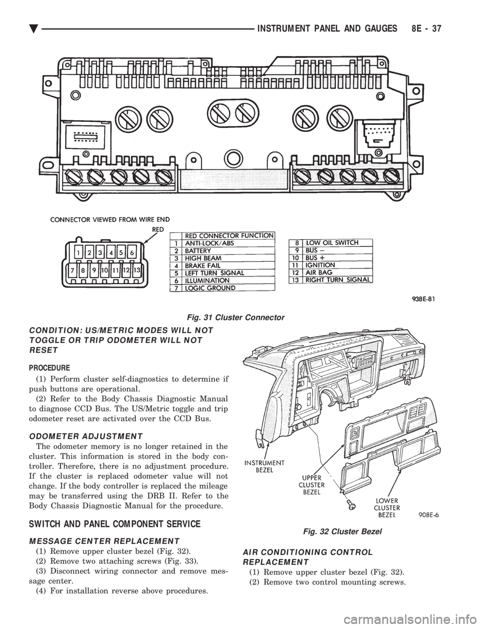
(1) Remove upper cluster bezel (Fig. 32).
(2) Remove two attaching screws (Fig. 33).
(3) Disconnect wiring connector and remove mes-
sage center. (4) For installation reverse above procedures.AIR CONDITIONING CONTROLREPLACEMENT
(1) Remove upper cluster bezel (Fig. 32).
(2) Remove two control mounting screws.
Fig. 31 Cluster Connector
Fig. 32 Cluster Bezel
Ä INSTRUMENT PANEL AND GAUGES 8E - 37
Page 546 of 2438

INSTALLATION (1) Latch switch linkage in the up position.
(2) Insert dimmer shaft into dimmer knob while
aligning switch in to switch pod assembly. (3) Install switch attaching screws.
(4) Unlatch linkage and install onto push buttons.
(5) Operate all switch modes for correct operation.
(6) Install turn signal switch.
(7) Reconnect wiring for turn signal switch, mak-
ing sure wire is properly clipped into position. (8) Place together the inner and outer bezels. In-
stall five inner switch pod panel screws and three
screws from underneath the switch pod. (9) Install turn signal lever by pushing straight
into switch assembly. (10) Install switch pod assembly.
LOWER STEERING COLUMN COVER REMOVAL
(1) Remove screws along top edge of cover.
(2) Remove screw at each lower corner of cover. (3) Remove cover from underneath over column
cover. (4) For installation reverse above procedures.
GLOVEBOX MODULE REMOVAL
(1) Disconnect battery negative cable and isolate
or remove fuse #26 prior to removing switch or wires
may short to ground. (2) Remove cowl side trim panel.
(3) Remove screws at right end of glovebox and
lower corners. (4) Open glovebox, remove light and disconnect
wiring. (5) Remove five screws along top of glovebox frame
and screw at each lower corner. (6) Remove glovebox assembly.
(7) For installation reverse above procedures.
CONCEALED HEADLAMP MODULE REMOVAL
(1) Remove left under panel silencer.
(2) Slide module off bayonet bracket while disen-
gaging spring retainer. (3) Disconnect wiring terminal.
(4) For installation reverse above procedures.
HOOD RELEASE REMOVE
(1) Remove lower column cover.
(2) Remove screws on fuse block and move aside.
(3) Remove screws on hood release assembly to re-
move. (4) For installation reverse above procedures.
AIR CONDITIONING CONTROL REMOVE
(1) Remove center stack bezel.
(2) Remove two control mounting screws (Fig. 28
and 29).
(3) Slide control rearward, disconnect cable, vac-
uum harness, and electrical wiring. With automatic
temperature control, disconnect wiring connector; be-
ing careful not to break off locking tab. (4) For installation reverse above procedures.
Fig. 26 Switch Pod Assembly
Fig. 27 Headlamp Multi-Function Switch
Fig. 28 A/C Control
8E - 54 INSTRUMENT PANEL AND GAUGES Ä