1993 CHEVROLET PLYMOUTH ACCLAIM oil pressure
[x] Cancel search: oil pressurePage 1803 of 2438
mode, the PCM compensates for the failure of certain
components that send incorrect signals. The PCM
substitutes for the incorrect signals with inputs from
other sensors and by using stored default values.Signals that can trigger the Malfunction Indi-
cator (Check Engine) Lamp.
² An emission system component
² Battery Voltage Input
² Charging system
² Engine Coolant Temperature Sensor
² Manifold Absolute Pressure Sensor
² Methanol Concentration Sensor
² Throttle Position Sensor
The malfunction indicator lamp can also display
diagnostic trouble codes. Cycle the ignition switch on,
off, on, off, on, within five seconds and the PCM
displays any diagnostic trouble codes stored in
memory. Refer to the 2.5L Flexible Fuel Multi-Port
Fuel InjectionÐOn Board Diagnostics section in this
group for diagnostic trouble code descriptions.
RADIATOR FAN RELAYÐPCM OUTPUT
The radiator fan is energized by the PCM through
the radiator fan relay. The PCM grounds the radiator
fan relay when engine coolant reaches a predetermined
temperature. For more information, refer to Group 7,
Cooling Systems. The radiator fan relay is mounted on the drivers side
fender well, next to the strut tower (Fig. 11).
SPEED CONTROL SOLENOIDSÐPCM OUTPUT
The speed control vacuum and vent solenoids are
operated by the PCM. When the PCM supplies a
ground to the vacuum and vent solenoids, the speed
control system opens the throttle blade. When the PCM
supplies a ground only to the vent solenoid, the throttle
blade holds position. When the PCM removes the
ground from both the vacuum and vent solenoids, the
throttle blade closes. The PCM balances the two sole-
noids to maintain the set speed. Refer to Group 8H for
speed control information.
TACHOMETERÐPCM OUTPUT
The PCM supplies engine RPM to the instrument
panel tachometer. Refer to Group 8 for tachometer
information.
TORQUE CONVERTER CLUTCH SOLENOIDÐPCM
OUTPUT
Three-speed automatic transaxles use a torque con-
verter clutch solenoid. The PCM controls the lock-up of
the torque convertor through the solenoid. The tran-
saxle is locked up only in direct drive mode. Refer to
Group 21 for transaxle information.
MODES OF OPERATION
As input signals to the PCM change, the PCM
adjusts its response to the output devices. For example, the PCM must calculate a different injector pulse
width and ignition timing for idle than it does for wide
open throttle (WOT). There are several different modes
of operation that determine how the PCM responds to
the various input signals. There are two different areas of operation, Open
Loop and Closed Loop. During Open Loop modes, the PCM receives input
signals and responds according to preset PCM pro-
gramming. Input from the oxygen (O
2) sensor is not
monitored during Open Loop modes. During CLOSED LOOP modes, the PCM does moni-
tor the oxygen (O
2) sensor input. The input indicates if
the calculated injector pulse width results in the ideal
air-fuel ratio for the current percentage of methanol in
the fuel. By monitoring the exhaust oxygen content
through the O
2sensor, the PCM can fine tune the
injector pulse width to achieve optimum fuel economy
combined with low emissions. The 2.5L flexible fuel multi-port fuel injection system
has the following modes of operation:
² Ignition switch ON - Zero RPM
² Engine start-up
² Engine warm-up
² Cruise (Idle)
² Acceleration
² Deceleration
² Wide Open Throttle
² Ignition switch OFF
The engine start-up (crank), engine warm-up, and
wide open throttle modes are OPEN LOOP modes. The
acceleration, deceleration, and cruise modes, with the
engine at operating temperature are CLOSED
LOOP modes (under most operating conditions).
IGNITION SWITCH ON (ZERO RPM) MODE
When the ignition switch cycles and past the On
position, the fuel injection system activates and the
following actions occur:
² For two seconds at key ON (and during cranking),
the methanol concentration sensor calibrates the PCM.
During the calibration period the sensor sends 4.45
volts to the PCM as a correction factor. After the
calibration period, the methanol concentration sensor
output represents the methanol percentage in the fuel.
² The PCM calculates basic fuel strategy by determin-
ing atmospheric air pressure from the MAP sensor
input.
² The PCM monitors the coolant temperature sensor
and throttle position sensor input. The PCM modifies
fuel strategy based on this input. When the key is in the ON position and the engine is
not running, the auto shutdown (ASD) relay and fuel
pump relay are not energized. Therefore battery volt-
age is not supplied to the fuel pump, ignition coil, fuel
injector or oxygen sensor heating element.
Ä FUEL SYSTEMS 14 - 63
Page 1804 of 2438
ENGINE START-UP MODE
This is an OPEN LOOP mode. The following ac-
tions occur when the starter motor is engaged. The methanol concentration sensor finishes cali-
brating the PCM (takes approximately two seconds).
After the calibration period, the PCM determines the
methanol content of the fuel from the methanol con-
centration sensor input. If the PCM receives a camshaft position sensor
(distributor pick-up) signal it energizes the auto
shutdown (ASD) relay and fuel pump relay. These re-
lays supply battery voltage to the fuel injector, igni-
tion coil and oxygen sensor heating element. If the
PCM does not receive a camshaft position sensor sig-
nal, it de-energizes the ASD and fuel pump relays af-
ter approximately one second. With the engine idling within 664 RPM of the tar-
get RPM, the PCM compares the current MAP value
with the atmospheric pressure value it received dur-
ing the Ignition Switch On (Zero RPM) Mode. If a
minimum difference between the two is not detected,
a MAP sensor fault is set into memory. Once the ASD relay and fuel pump relay have en-
ergized, the PCM:
² Supplies a ground path to each injector. The injec-
tors are pulsed four times per engine revolution in-
stead of the normal two pulses per revolution.
² Determines injector pulse width based on engine
coolant temperature, methanol concentration sensor
input, MAP sensor input, throttle position, and the
number of engine revolutions since cranking was ini-
tiated.
² Monitors the coolant temperature sensor, camshaft
position sensor, MAP sensor, methanol concentration
sensor, and throttle position sensor to determine cor-
rect ignition timing.
ENGINE WARM-UP MODE
This is a OPEN LOOP mode. The following inputs
are received by the PCM:
² Engine coolant temperature
² Engine speed
² Manifold absolute pressure (MAP)
² Methanol percentage in fuel
² Throttle position
² A/C switch
² Battery voltage
The PCM determines the methanol content of the
fuel from the methanol concentration sensor input. The PCM provides a ground path for the injectors
and energizes them in sequence. The PCM precisely
controls injector pulse width by switching the ground
on and off. The PCM regulates engine idle speed by adjusting
the idle air control motor. Also, the PCM adjusts ig-
nition timing.
CRUISE OR IDLE MODE
When the engine is at operating temperature, this
is a CLOSED LOOP mode. During cruising speed the
following inputs are received by the PCM:
² Engine coolant temperature
² Manifold absolute pressure
² Methanol percentage in fuel
² Engine speed
² Throttle position
² Exhaust gas oxygen content
² A/C control positions
² Battery voltage
The PCM determines the methanol content of the
fuel from the methanol concentration sensor input. The PCM provides a ground path for the injectors
to precisely control injector pulse width. The PCM
controls engine idle speed and ignition timing. The
PCM controls the air/fuel ratio according to the oxy-
gen content in the exhaust gas.
ACCELERATION MODE
This is a CLOSED LOOP mode. The PCM recog-
nizes an abrupt increase in throttle position or MAP
pressure as a demand for increased engine output
and vehicle acceleration. The PCM increases injector
pulse width in response to increased fuel demand.
DECELERATION MODE
This is a CLOSED LOOP mode. During decelera-
tion the following inputs are received by the PCM:
² Engine coolant temperature
² Manifold absolute pressure
² Methanol percentage in fuel
² Engine speed
² Throttle position
² Exhaust gas oxygen content
² A/C control positions
² Battery voltage
The PCM may receive a closed throttle input from
the TPS at the same time it senses an abrupt de-
crease in manifold absolute pressure. This indicates a
hard deceleration. In response, the PCM may modify
the injector firing sequence. Modifying the injector
firing sequence helps maintain better control of the
air-fuel mixture (as sensed through the O
2sensor).
WIDE OPEN THROTTLE MODE
This is an OPEN LOOP mode. During wide open
throttle operation, the following inputs are received
by the PCM:
² Engine coolant temperature
² Manifold absolute pressure
² Methanol percentage in fuel
² Engine speed
² Throttle position
When the PCM senses a wide open throttle condi-
tion, it de-energizes the air conditioning clutch relay.
This disables the air conditioning system.
14 - 64 FUEL SYSTEMS Ä
Page 1811 of 2438
the PCM to store diagnostic trouble codes for other
systems. For example, a fuel pressure problem will not
register a fault directly, but could cause a rich or lean
condition. This could cause the PCM to store an oxygen
sensor diagnostic trouble code. Fuel Pressure - The vacuum assisted fuel pressure
regulator controls fuel system pressure. The PCM
cannot detect a clogged fuel pump inlet filter, clogged
in-line fuel filter, stuck open regulator, or a pinched
fuel supply or return line. However, these could result
in a rich or lean condition causing the PCM to store an
oxygen sensor diagnostic trouble code. Secondary Ignition Circuit - The PCM cannot
detect an inoperative ignition coil, fouled or worn spark
plugs, ignition cross firing, or open spark plug cables. Engine Timing - The PCM cannot detect an incor-
rectly indexed timing belt, camshaft sprocket and
crankshaft sprocket. However, these could result in a
rich or lean condition causing the PCM to store an
oxygen sensor diagnostic trouble code. Cylinder Compression - The PCM cannot detect
uneven, low, or high engine cylinder compression. Exhaust System - The PCM cannot detect a
plugged, restricted or leaking exhaust system. Fuel Injector Mechanical Malfunctions - The
PCM cannot determine if a fuel injector is clogged, the
needle is sticking or if the wrong injector is installed.
However, these could result in a rich or lean condition
causing the PCM to store an oxygen sensor diagnostic
trouble code. Excessive Oil Consumption - Although the PCM
monitors exhaust stream oxygen content when the
system is in closed loop, it cannot determine excessive
oil consumption. Throttle Body Air Flow - The PCM cannot detect a
clogged or restricted air cleaner inlet or filter element. Evaporative System - The PCM cannot detect a
disconnected (open vacuum line) restricted, plugged or
loaded evaporative purge canister. Vacuum Assist - The PCM cannot detect leaks or
restrictions in the vacuum circuits of vacuum assisted
engine control system devices. However, these could
cause the PCM to store a MAP sensor diagnostic
trouble code and cause a high idle condition. PCM System Ground - The PCM cannot determine
a poor system ground. However, one or more diagnostic
trouble codes may be generated as a result of this
condition. PCM Connector Engagement - The PCM may not
be able to determine spread or damaged connector
pins. However, it might store diagnostic trouble codes
as a result of spread connector pins.HIGH AND LOW LIMITS
The PCM compares input signal voltages from each
input device with established high and low limits for the
device. If the input voltage is not within limits and other
criteria are met, the PCM stores a diagnostic trouble code
in memory. Other diagnostic trouble code criteria might
include engine RPM limits or input voltages from other
sensors or switches that must be present before verifying
a diagnostic trouble code condition.
DIAGNOSTIC TROUBLE CODES
A diagnostic trouble code indicates the powertrain
control module (PCM) has recognized an abnormal
condition in the system. Abnormal conditions are usu-
ally shorted or open circuits.
The technician can display diagnostic trouble codes in
two ways. The first way is to cycle the ignition switch and
count the number of times the malfunction indicator lamp
(check engine lamp on the instrument panel) flashes on
and off. The DRBII scan tool provides the second method
of displaying diagnostic trouble codes. Diagnostic trouble
codes indicate the results of a circuit failure, but do not
directly identify the failed component.
For a list of Diagnostic Trouble Codes, refer to
the charts at the end of this section.
OBTAINING DIAGNOSTIC TROUBLE CODES
USING DRBII SCAN TOOL
WARNING: APPLY PARKING BRAKE AND/OR BLOCK
WHEELS BEFORE PERFORMING ANY TEST ON AN
OPERATING ENGINE. (1) Connect DRBII scan tool to the data link (diag-
nostic) connector located in the engine compartment,
next to the PCM (Fig. 1). (2) If possible, start the engine and cycle the A/C
switch if applicable. Shut off the engine. (3)
Turn the ignition switch on, access Read Fault
Screen. Record all the diagnostic trouble codes shown on
the DRBII scan tool. [Observe the malfunction indicator
lamp (check engine lamp) on the instrument panel. The
lamp should light for 2 seconds then go out (bulb check)].
To erase diagnostic trouble codes, use the Erase
Trouble Code data screen on the DRBII scan tool.
USING THE MALFUNCTION INDICATOR LAMP (1) Cycle the ignition key On - Off - On - Off - On
within 5 seconds. (2) Count the number of times the malfunction indi-
cator lamp (check engine lamp on the instrument
panel) flashes on and off. The number of flashes
represents the trouble code. There is a slight pause be-
Ä FUEL SYSTEMS 14 - 71
Page 1812 of 2438
tween the flashes representing the first and second
digits of the code. Longer pauses separate individual
trouble codes.(3) Refer to the Diagnostic Trouble Code Charts at
the end of this group.
STATE DISPLAY TEST MODE
The switch inputs to the powertrain control module
(PCM) have two recognized states; HIGH and LOW.
For this reason, the PCM cannot recognize the differ-
ence between a selected switch position versus an
open circuit, a short circuit, or a defective switch. If
the State Display screen shows the change from
HIGH to LOW or LOW to HIGH, assume the entire
switch circuit to the PCM functions properly. From
the state display screen, access either State Display
Inputs and Outputs or State Display Sensors.
STATE DISPLAY INPUTS AND OUTPUTS
Connect the DRBII scan tool to the vehicle and ac-
cess the State Display screen. Then access Inputs and
Outputs. The following is a list of the engine control
system functions accessible through the Inputs and
Outputs screen.
² Park/Neutral Switch (automatic transaxle only)
² Speed Control Resume
² Speed Control On/Off
² Speed Control Set
² Brake Switch
² A/C Switch Sense
² S/C Vent Solenoid
² S/C Vacuum Solenoid
² A/C Clutch Relay
² Auto Shutdown Relay
² Radiator Fan Relay
² (Duty Cycle) EVAP Purge Solenoid
² Malfunction Indicator (Check Engine) Lamp
STATE DISPLAY SENSORS
Connect the DRBII scan tool to the vehicle and ac-
cess the State Display screen. Then access Sensor
Display. The following is a list of the engine control
system functions accessible through the Sensor Dis-
play screen.
² Oxygen Sensor Signal
² Engine Coolant Temperature
² Engine Coolant Temp Sensor
² Throttle Position
² Minimum Throttle
² Battery Voltage
² MAP Sensor Reading
² Idle Air Control Motor Position
² Adaptive Fuel Factor
² Barometric Pressure
² Min Airflow Idle Spd (Speed)
² Engine Speed
² Fault #1 Key-On Info
² Module Spark Advance ²
Speed Control Target
² Fault #2 Key-on Info
² Fault #3 Key-on Info
² Speed Control Status
² Charging System Goal
² Theft Alarm Status
² Battery Temperature
² Flex Fuel (Methanol Concentration) Sensor Volt-
age
² Methanol Content (percentage)
² Map Sensor Voltage
² Vehicle Speed
² Oxygen Sensor State
² MAP Gauge Reading
² Throttle Opening (percentage)
² Total Spark Advance
CIRCUIT ACTUATION TEST MODE
The Circuit Actuation Test Mode checks for proper
operation of output circuits or devices the powertrain
control module (PCM) cannot internally recognize.
The PCM attempts to activate these outputs and al-
low an observer to verify proper operation. Most of
the tests provide an audible or visual indication of
device operation (click of relay contacts, fuel spray,
etc.). Except for intermittent conditions, if a device
functions properly during testing, assume the device,
its associated wiring, and driver circuit work cor-
rectly.
OBTAINING CIRCUIT ACTUATION TEST
Connect the DRBII scan tool to the vehicle and ac-
cess the Actuators screen. The following is a list of
the engine control system functions accessible
through Actuators screens. Subordinate screens for
each actuator test are also listed. Stop All Tests
Ignition Coil No. 1
Fuel Injector No. 1
Fuel Injector No. 2
Fuel Injector No. 3
Fuel Injector No. 4
Idle Air Control Motor Open/Close
Fuel System
Radiator Fan Relay
A/C Clutch Relay
Auto Shutdown Relay
EVAP Purge Solenoid
Speed Control Servo Solenoids
Generator Field
Tachometer Output
Torque Converter Clutch Solenoid
All Solenoids/Relays
Speed Control Vent Solenoid
Speed Control Vacuum Solenoid
ASD Fuel System Test
14 - 72 FUEL SYSTEMS Ä
Page 1820 of 2438
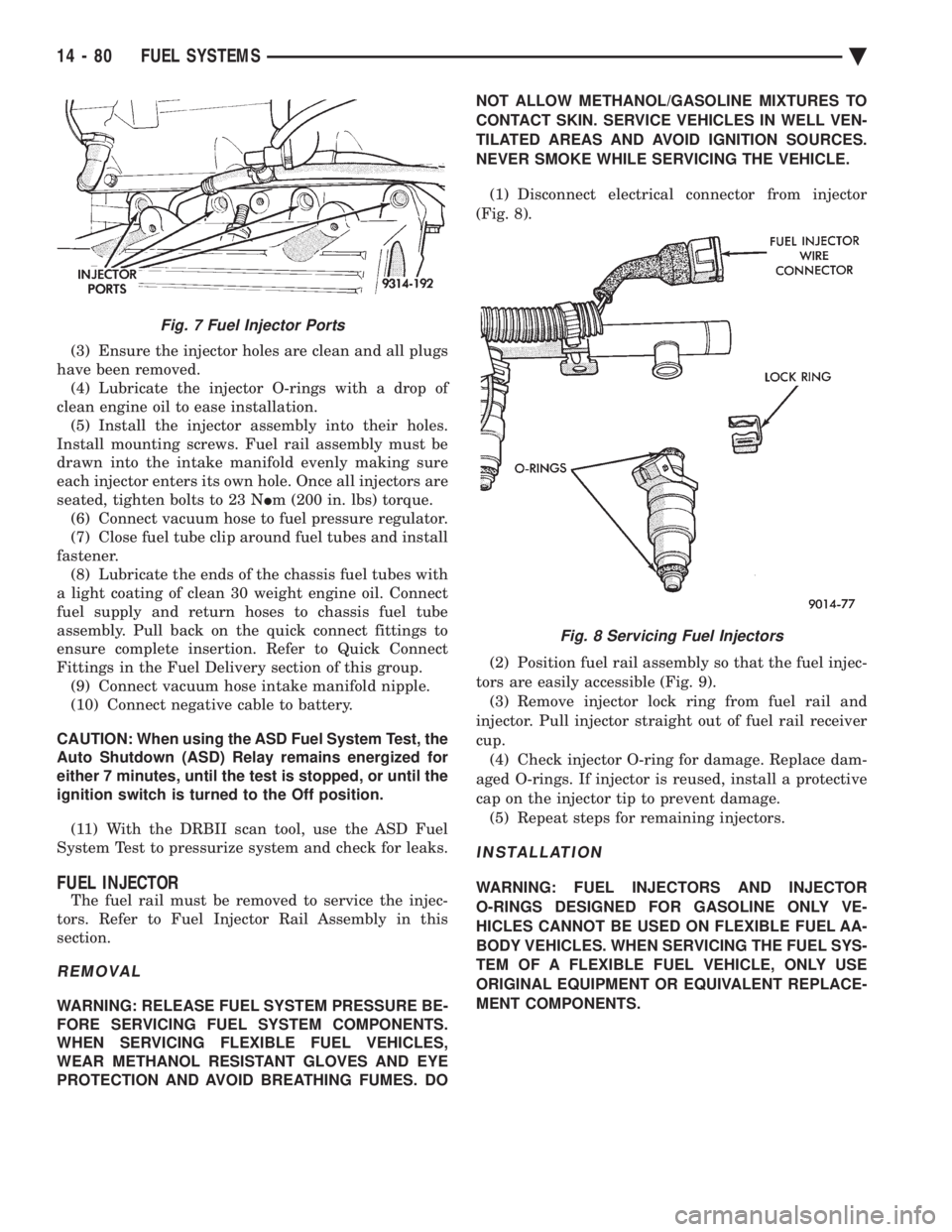
(3) Ensure the injector holes are clean and all plugs
have been removed. (4) Lubricate the injector O-rings with a drop of
clean engine oil to ease installation. (5) Install the injector assembly into their holes.
Install mounting screws. Fuel rail assembly must be
drawn into the intake manifold evenly making sure
each injector enters its own hole. Once all injectors are
seated, tighten bolts to 23 N Im (200 in. lbs) torque.
(6) Connect vacuum hose to fuel pressure regulator.
(7) Close fuel tube clip around fuel tubes and install
fastener. (8) Lubricate the ends of the chassis fuel tubes with
a light coating of clean 30 weight engine oil. Connect
fuel supply and return hoses to chassis fuel tube
assembly. Pull back on the quick connect fittings to
ensure complete insertion. Refer to Quick Connect
Fittings in the Fuel Delivery section of this group. (9) Connect vacuum hose intake manifold nipple.
(10) Connect negative cable to battery.
CAUTION: When using the ASD Fuel System Test, the
Auto Shutdown (ASD) Relay remains energized for
either 7 minutes, until the test is stopped, or until the
ignition switch is turned to the Off position.
(11) With the DRBII scan tool, use the ASD Fuel
System Test to pressurize system and check for leaks.
FUEL INJECTOR
The fuel rail must be removed to service the injec-
tors. Refer to Fuel Injector Rail Assembly in this
section.
REMOVAL
WARNING: RELEASE FUEL SYSTEM PRESSURE BE-
FORE SERVICING FUEL SYSTEM COMPONENTS.
WHEN SERVICING FLEXIBLE FUEL VEHICLES,
WEAR METHANOL RESISTANT GLOVES AND EYE
PROTECTION AND AVOID BREATHING FUMES. DO NOT ALLOW METHANOL/GASOLINE MIXTURES TO
CONTACT SKIN. SERVICE VEHICLES IN WELL VEN-
TILATED AREAS AND AVOID IGNITION SOURCES.
NEVER SMOKE WHILE SERVICING THE VEHICLE.
(1) Disconnect electrical connector from injector
(Fig. 8).
(2) Position fuel rail assembly so that the fuel injec-
tors are easily accessible (Fig. 9). (3) Remove injector lock ring from fuel rail and
injector. Pull injector straight out of fuel rail receiver
cup. (4) Check injector O-ring for damage. Replace dam-
aged O-rings. If injector is reused, install a protective
cap on the injector tip to prevent damage. (5) Repeat steps for remaining injectors.
INSTALLATION
WARNING: FUEL INJECTORS AND INJECTOR
O-RINGS DESIGNED FOR GASOLINE ONLY VE-
HICLES CANNOT BE USED ON FLEXIBLE FUEL AA-
BODY VEHICLES. WHEN SERVICING THE FUEL SYS-
TEM OF A FLEXIBLE FUEL VEHICLE, ONLY USE
ORIGINAL EQUIPMENT OR EQUIVALENT REPLACE-
MENT COMPONENTS.
Fig. 7 Fuel Injector Ports
Fig. 8 Servicing Fuel Injectors
14 - 80 FUEL SYSTEMS Ä
Page 1821 of 2438
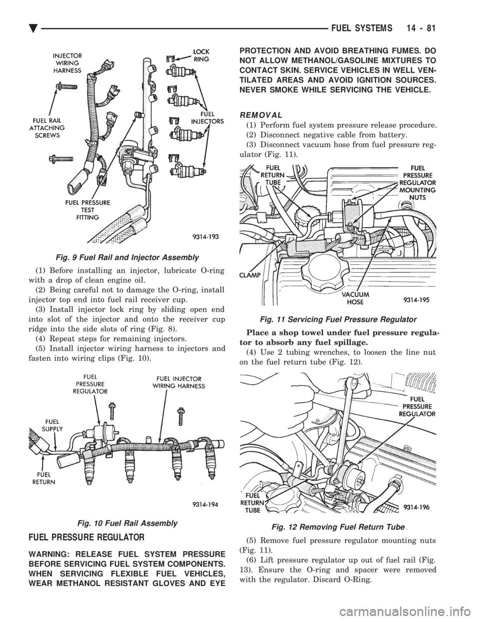
(1) Before installing an injector, lubricate O-ring
with a drop of clean engine oil. (2) Being careful not to damage the O-ring, install
injector top end into fuel rail receiver cup. (3) Install injector lock ring by sliding open end
into slot of the injector and onto the receiver cup
ridge into the side slots of ring (Fig. 8). (4) Repeat steps for remaining injectors.
(5) Install injector wiring harness to injectors and
fasten into wiring clips (Fig. 10).
FUEL PRESSURE REGULATOR
WARNING: RELEASE FUEL SYSTEM PRESSURE
BEFORE SERVICING FUEL SYSTEM COMPONENTS.
WHEN SERVICING FLEXIBLE FUEL VEHICLES,
WEAR METHANOL RESISTANT GLOVES AND EYE PROTECTION AND AVOID BREATHING FUMES. DO
NOT ALLOW METHANOL/GASOLINE MIXTURES TO
CONTACT SKIN. SERVICE VEHICLES IN WELL VEN-
TILATED AREAS AND AVOID IGNITION SOURCES.
NEVER SMOKE WHILE SERVICING THE VEHICLE.
REMOVAL
(1) Perform fuel system pressure release procedure.
(2) Disconnect negative cable from battery.
(3) Disconnect vacuum hose from fuel pressure reg-
ulator (Fig. 11).
Place a shop towel under fuel pressure regula-
tor to absorb any fuel spillage. (4) Use 2 tubing wrenches, to loosen the line nut
on the fuel return tube (Fig. 12).
(5) Remove fuel pressure regulator mounting nuts
(Fig. 11). (6) Lift pressure regulator up out of fuel rail (Fig.
13). Ensure the O-ring and spacer were removed
with the regulator. Discard O-Ring.
Fig. 9 Fuel Rail and Injector Assembly
Fig. 10 Fuel Rail Assembly
Fig. 11 Servicing Fuel Pressure Regulator
Fig. 12 Removing Fuel Return Tube
Ä FUEL SYSTEMS 14 - 81
Page 1822 of 2438
INSTALLATION
WARNING: THE FUEL PRESSURE REGULATOR,
O-RING AND SPACER DESIGNED FOR GASOLINE
ONLY VEHICLES CANNOT BE USED ON FLEXIBLE
FUEL AA-BODY VEHICLES. WHEN SERVICING THE
FUEL SYSTEM OF A FLEXIBLE FUEL VEHICLE,
ONLY USE ORIGINAL EQUIPMENT OR EQUIVA-
LENT REPLACEMENT COMPONENTS.
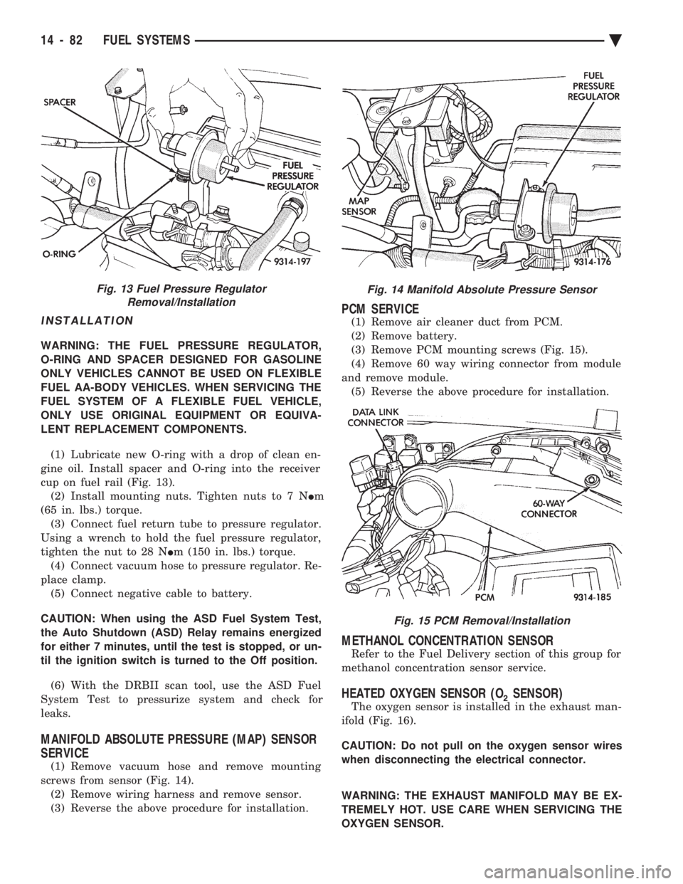
(1) Lubricate new O-ring with a drop of clean en-
gine oil. Install spacer and O-ring into the receiver
cup on fuel rail (Fig. 13). (2) Install mounting nuts. Tighten nuts to 7 N Im
(65 in. lbs.) torque. (3) Connect fuel return tube to pressure regulator.
Using a wrench to hold the fuel pressure regulator,
tighten the nut to 28 N Im (150 in. lbs.) torque.
(4) Connect vacuum hose to pressure regulator. Re-
place clamp. (5) Connect negative cable to battery.
CAUTION: When using the ASD Fuel System Test,
the Auto Shutdown (ASD) Relay remains energized
for either 7 minutes, until the test is stopped, or un-
til the ignition switch is turned to the Off position.
(6) With the DRBII scan tool, use the ASD Fuel
System Test to pressurize system and check for
leaks.
MANIFOLD ABSOLUTE PRESSURE (MAP) SENSOR
SERVICE
(1) Remove vacuum hose and remove mounting
screws from sensor (Fig. 14). (2) Remove wiring harness and remove sensor.
(3) Reverse the above procedure for installation.
PCM SERVICE
(1) Remove air cleaner duct from PCM.
(2) Remove battery.
(3) Remove PCM mounting screws (Fig. 15).
(4) Remove 60 way wiring connector from module
and remove module. (5) Reverse the above procedure for installation.
METHANOL CONCENTRATION SENSOR
Refer to the Fuel Delivery section of this group for
methanol concentration sensor service.
HEATED OXYGEN SENSOR (O2SENSOR)
The oxygen sensor is installed in the exhaust man-
ifold (Fig. 16).
CAUTION: Do not pull on the oxygen sensor wires
when disconnecting the electrical connector.
WARNING: THE EXHAUST MANIFOLD MAY BE EX-
TREMELY HOT. USE CARE WHEN SERVICING THE
OXYGEN SENSOR.
Fig. 13 Fuel Pressure Regulator Removal/InstallationFig. 14 Manifold Absolute Pressure Sensor
Fig. 15 PCM Removal/Installation
14 - 82 FUEL SYSTEMS Ä
Page 1823 of 2438
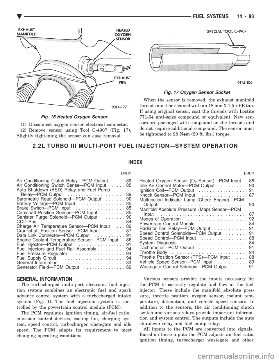
(1) Disconnect oxygen sensor electrical connector.
(2) Remove sensor using Tool C-4907 (Fig. 17).
Slightly tightening the sensor can ease removal. When the sensor is removed, the exhaust manifold
threads must be cleaned with an 18 mm X 1.5 + 6E tap.
If using original sensor, coat the threads with Loctite
771-64 anti-seize compound or equivalent. New sen-
sors are packaged with compound on the threads and
do not require additional compound. The sensor must
be tightened to 28 N Im (20 ft. lbs.) torque.
2.2L TURBO III MULTI-PORT FUEL INJECTIONÐSYSTEM OPERATION
INDEX
page page
Air Conditioning Clutch RelayÐPCM Output .... 89
Air Conditioning Switch SenseÐPCM Input ..... 85
Auto Shutdown (ASD) Relay and Fuel Pump RelayÐPCM Output ..................... 89
Barometric Read SolenoidÐPCM Output ....... 90
Battery VoltageÐPCM Input ................ 85
Brake SwitchÐPCM Input .................. 85
Camshaft Position SensorÐPCM Input ........ 85
Canister Purge SolenoidÐPCM Output ........ 90
CCD Bus .............................. 84
Charge Air Temperature SensorÐPCM Input . . . 86
Crankshaft Position SensorÐPCM Input ....... 87
Data Link ConnectorÐPCM Output ........... 91
Engine Coolant Temperature SensorÐPCM Input . 86
Fuel InjectorÐPCM Output ................. 91
Fuel Injectors and Fuel Rail Assembly ......... 94
Fuel Pressure Regulator ................... 94
Fuel Supply Circuit ....................... 94
General Information ....................... 83
Generator FieldÐPCM Output ............... 89 Heated Oxygen Sensor (O
2Sensor)ÐPCM Input . 88
Idle Air Control MotorÐPCM Output .......... 90
Ignition CoilÐPCM Output .................. 91
Knock SensorÐPCM Input ................. 87
Malfunction Indicator Lamp (Check Engine)ÐPCM Output ............................... 90
Manifold Absolute Pressure (Map) SensorÐPCM Input ................................ 87
Modes of Operation ....................... 92
Powertrain Control Module ................. 84
Radiator Fan RelayÐPCM Output ............ 91
Speed Control SolenoidsÐPCM Output ........ 91
Speed ControlÐPCM Input ................. 88
System Diagnosis ........................ 84
TachometerÐPCM Output .................. 91
Throttle Body ............................ 94
Throttle Position Sensor (TPS)ÐPCM Input ..... 88
Vehicle Speed SensorÐPCM Input ........... 89
Wastegate Control SolenoidÐPCM Output ..... 91
GENERAL INFORMATION
The turbocharged multi-port electronic fuel injec-
tion system combines an electronic fuel and spark
advance control system with a turbocharged intake
system (Fig. 1). The fuel injection system is con-
trolled by the powertrain control module (PCM). The PCM regulates ignition timing, air-fuel ratio,
emission control devices, cooling fan, charging sys-
tem, speed control, turbocharger wastegate and idle
speed. The PCM adapts its requirement to meet
changing operating conditions. Various sensors provide the inputs necessary for
the PCM to correctly regulate fuel flow at the fuel
injector. These include the manifold absolute pres-
sure, throttle position, oxygen sensor, coolant tem-
perature, detonation, and vehicle speed sensors. In
addition to the sensors, the air conditioning clutch
switch and various relays provide important informa-
tion and system control. The outputs include the auto
shutdown relay and fuel pump relay. All inputs to the PCM are converted into signals.
Based on these inputs the PCM adjusts air-fuel ratio,
ignition timing, turbocharger wastegate and other
Fig. 16 Heated Oxygen Sensor
Fig. 17 Oxygen Sensor Socket
Ä FUEL SYSTEMS 14 - 83