1993 CHEVROLET DYNASTY check engine light
[x] Cancel search: check engine lightPage 1844 of 2438
SYSTEM TESTS
Apply parking brake and/or block wheels be-
fore performing idle check or adjustment, or any
engine running tests.
OBTAINING DIAGNOSTIC TROUBLE CODES
(1) Connect DRBII scan tool to the data link connec-
tor (Fig. 1). (2) Start the engine if possible, cycle the trans mis-
sion selector and the A/Cswitch if applicable. Shut off
the engine. (3) Turn the ignition switch on, access Read Fault
Screen. Record all the fault messages shown on the
DRBII scan tool. Observe the malfunction indicator
lamp (check engine lamp on the instrument panel). The
lamp should light for 2 seconds then go out (bulb
check). Diagnostic trouble code erasure: access erase
diagnostic trouble code data.
STATE DISPLAY TEST MODE
The switch inputs used by the powertrain control
module (PCM) have only two recognized states, HIGH
and LOW. For this reason, the PCM cannot recognize
the difference between a selected switch position ver-
sus an open circuit, a short circuit, or a defective
switch. If the display changes, assume the entire
switch circuit to the PCM is functional. From the state
display screen access either State Display Inputs and
Outputs or State Display Sensors.
STATE DISPLAY INPUTS AND OUTPUTS
Connect the DRBII scan tool to the vehicle and access
the State Display screen. Then access Inputs and
Outputs. The following is a list of the engine control
system functions accessible through the Inputs and
Outputs screen. Speed Control Resume
Brake Switch
Speed Control On/Off
Speed Control Set
A/C Switch Sense
S/C Vent Solenoid S/C Vacuum Solenoid
A/C Clutch Relay
Baro Read Solenoid
Wastegate Solenoid
Auto Shutdown Relay
Radiator Fan Relay
Purge Solenoid
Malfunction Indicator Lamp (Check Engine Lamp)
STATE DISPLAY SENSORS
Connect the DRBII scan tool to the vehicle and ac-
cess the State Display screen. Then access Sensor
Display. The following is a list of the engine control
system functions accessible through the Sensor Dis-
play screen. Oxygen Sensor Signal
Coolant Temperature
Coolant Temp Sensor
Throttle Position
Minimum Throttle
Knock Sensor Signal
Battery Voltage
MAP Sensor Reading
Idle Air Control Motor Position
Adaptive Fuel Factor
Barometric Pressure
Min Airflow Idle Spd (speed)
Engine Speed
DIS Sensor Status
Fault #1 Key-On Info
Module Spark Advance
Cyl 1 Knock Retard
Cyl 2 Knock Retard
Cyl 3 Knock Retard
Cyl 4 Knock Retard
Boost Pressure Goal
Charge Temperature
Charge Temp Sensor
Speed Control Target
Fault #2 Key-on Info
Fault #3 Key-on Info
Speed Control Status
Charging System Goal
Theft Alarm Status
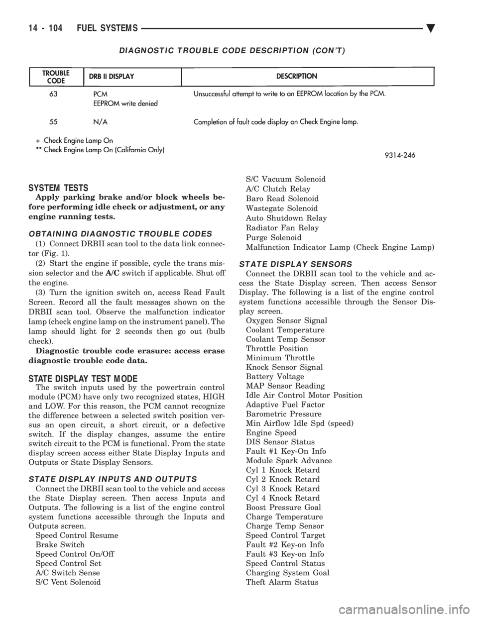
DIAGNOSTIC TROUBLE CODE DESCRIPTION (CON'T)
14 - 104 FUEL SYSTEMS Ä
Page 1874 of 2438
SYSTEM TESTS
WARNING: APPLY PARKING BRAKE AND/OR BLOCK
WHEELS BEFORE PERFORMING ANY TEST ON AN
OPERATING ENGINE.
OBTAINING DIAGNOSTIC TROUBLE CODES
(1) Connect DRBII scan tool to the data link connec-
tor located in the engine compartment near the pow-
ertrain control module (PCM). (2) Start the engine if possible, cycle the transaxle
selector and the A/Cswitch if applicable. Shut off the
engine. (3) Turn the ignition switch on, access Read Fault
Screen. Record all the fault messages shown on the
DRBII scan tool. Observe the malfunction indicator
lamp (Check Engine lamp on the instrument panel).
The lamp should light for 3 seconds then go out (bulb
check). Diagnostic trouble code erasure; access erase
diagnostic trouble code data
STATE DISPLAY TEST MODE
The switch inputs used by the powertrain control
module (PCM) have only two recognized states, HIGH
and LOW. For this reason, the PCM cannot recognize
the difference between a selected switch position ver-
sus an open circuit, a short circuit, or a defective
switch. If the change is displayed, it can be assumed
that the entire switch circuit to the PCM is functional.
From the state display screen access either State
Display Inputs and Outputs or State Display Sensors.
STATE DISPLAY INPUTS AND OUTPUTS
Connect the DRBII scan tool to the vehicle. Access
the State Display screen. Then access Inputs and
Outputs. The following is a list of the engine control
system functions accessible through the Inputs and
Outputs screen. Park/Neutral Switch
Speed Control Resume
Brake Switch
Speed Control On/Off
Speed Control Set
A/C Switch Sense
S/C Vent Solenoid
S/C Vacuum Solenoid
A/C Clutch Relay
EGR Solenoid
Auto Shutdown Relay
Radiator Fan Relay
Purge Solenoid
Torque Converter Clutch Solenoid
Malfunction Indicator Lamp (Check Engine Lamp)
STATE DISPLAY SENSORS
Connect the DRBII scan tool to the vehicle and ac-
cess the State Display screen. Then access Sensor
Display. The following is a list of the engine control
system functions accessible through the Sensor Dis-
play screen. Battery Temperature
Oxygen Sensor Signal
Engine Coolant Temperature
Engine Coolant Temp Sensor
Throttle Position
Minimum Throttle
Battery Voltage
MAP Sensor Reading
Idle Air Control Motor Position
Adaptive Fuel Factor
Barometric Pressure
Min Airflow Idle Speed
Engine Speed
Fault #1 Key-On Info
Module Spark Advance
Speed Control Target
Fault #2 Key-on Info
Fault #3 Key-on Info
Speed Control Status
Speed Control Switch Voltage
Charging System Goal
Theft Alarm Status
Map Sensor Voltage
Vehicle Speed
Oxygen Sensor State
MAP Gauge Reading
Throttle Opening (percentage)
Total Spark Advance
CIRCUIT ACTUATION TEST MODE
The circuit actuation test mode checks for proper
operation of output circuits or devices which the pow-
ertrain control module (PCM) cannot internally rec-
ognize. The PCM can attempt to activate these
outputs and allow an observer to verify proper oper-
ation. Most of the tests provide an audible or visual
indication of device operation (click of relay contacts,
spray fuel, etc.). Except for intermittent conditions, if
a device functions properly during testing, assume
the device, its associated wiring, and driver circuit
working correctly.
OBTAINING CIRCUIT ACTUATION TEST
Connect the DRBII scan tool to the vehicle and ac-
cess the Actuators screen. The following is a list of
the engine control system functions accessible
through Actuators screens. Stop All Tests
Ignition Coil #1
Fuel Injector #1
Fuel Injector #2
Fuel Injector #3
14 - 134 FUEL SYSTEMS Ä
Page 1903 of 2438
line. However, these could result in a rich or lean
condition causing an oxygen sensor fault to be stored in
the PCM. Secondary Ignition Circuit - The PCM cannot
detect an inoperative ignition coil, fouled or worn spark
plugs, ignition cross firing, or open spark plug cables. Engine Timing - The PCM cannot detect an incor-
rectly indexed timing chain, camshaft sprocket and
crankshaft sprocket. However, these could result in a
rich or lean condition causing an oxygen sensor fault to
be stored in the PCM. Cylinder Compression - The PCM cannot detect
uneven, low, or high engine cylinder compression. Exhaust System - The PCM cannot detect a
plugged, restricted or leaking exhaust system. Fuel Injector Malfunctions - The PCM cannot
determine if a fuel injector is clogged, the needle is
sticking or the wrong injector is installed. However,
these could result in a rich or lean condition causing an
oxygen sensor fault to be stored in the PCM. Excessive Oil Consumption - Although the PCM
monitors exhaust stream oxygen content when the
system is in closed loop, it cannot determine excessive
oil consumption. Throttle Body Air Flow - The PCM cannot detect a
clogged or restricted air cleaner inlet or filter element. Evaporative System - The PCM will not detect a
restricted, plugged or loaded evaporative purge canis-
ter. Vacuum Assist - Leaks or restrictions in the
vacuum circuits of vacuum assisted engine control
system devices are not monitored by the PCM. How-
ever, these could result in a MAP sensor fault being
stored in the PCM. PCM System Ground - The PCM cannot determine
a poor system ground. However, a diagnostic trouble
code may be generated as a result of this condition. PCM Connector Engagement - The PCM cannot
determine spread or damaged connector pins. How-
ever, a diagnostic trouble code may be generated as a
result of this condition.
HIGH AND LOW LIMITS
The powertrain control module (PCM) compares in-
put signal voltages from each input device with estab-
lished high and low limits for the device. If the input
voltage is not within limits and other diagnostic
trouble code criteria are met, a diagnostic trouble code
will be stored in memory. Other diagnostic trouble code
criteria might include engine RPM limits or input
voltages from other sensors or switches that must be
present before a fault condition can be verified.
DIAGNOSTIC TROUBLE CODE DESCRIPTION
A diagnostic trouble code indicates that the power-
train control module (PCM) has recognized an abnor- mal condition in the system. Diagnostic trouble codes
can be obtained from the malfunction indicator lamp
(Check Engine lamp on the instrument panel) or from
the DRBII scan tool. Diagnostic trouble codes indicate
the results of a failure but do not identify the failed
component directly.
SYSTEM TESTS
WARNING: APPLY PARKING BRAKE AND/OR BLOCK
WHEELS BEFORE PERFORMING ANY TEST ON AN
OPERATING ENGINE.
OBTAINING DIAGNOSTIC TROUBLE CODES
(1) Connect the DRBII scan tool to the data link
connector located in the engine compartment near the
driver side strut tower (Fig. 1). (2) Start the engine if possible, cycle the transaxle
selector and the A/Cswitch if applicable. Shut off the
engine. (3) Turn the ignition switch on, access Read Fault
Screen. Record all the fault messages shown on the
DRBII scan tool. Observe the malfunction indicator
lamp (check engine lamp on the instrument panel). The
lamp should light for 2 seconds then go out (bulb
check). Diagnostic trouble code erasure; access erase
diagnostic trouble code data
STATE DISPLAY TEST MODE
The switch inputs used by the powertrain control
module (PCM) have only two recognized states, HIGH
and LOW. For this reason, the PCM cannot recognize
the difference between a selected switch position ver-
sus an open circuit, a short circuit, or a defective
switch. If the change is displayed, it can be assumed
that the entire switch circuit to the PCM is functional.
From the state display screen access either State
Display Inputs and Outputs or State Display Sensors.
STATE DISPLAY INPUTS AND OUTPUTS
Connect the DRBII scan tool to the vehicle and access
the State Display screen. Then access Inputs and
Outputs. The following is a list of the engine control
system functions accessible through the Inputs and
Outputs screen. Park/Neutral Switch
Speed Control Resume
Brake Switch
Speed Control On/Off
Speed Control Set
A/C Switch Sense
S/C Vent Solenoid
Ä FUEL SYSTEMS 14 - 163
Page 1942 of 2438
POWER STEERING PUMPÐINITIAL OPERATION
CAUTION: The fluid level should be checked with
engine off to prevent injury from moving compo-
nents. Use only Mopar TPower Steering Fluid. Do
not use automatic transmission fluid. Do not over-
fill.
Wipe filler cap clean, then check the fluid level.
The dipstick should indicate FULL COLDwhen the
fluid is at normal temperature of approximately 21ÉC
to 27ÉC (70ÉF to 80ÉF). (1) Fill power steering pump fluid reservoir to the
proper level. (2) Start the engine and let run for a few seconds.
Then turn the engine off.
(3) Add fluid if necessary. Repeat the above proce-
dure until the fluid level remains constant after run-
ning the engine. (4) Raise front wheels of vehicle off the ground.
(5) Start the engine. Slowly turn the steering
wheel right and left, lightly contacting the wheel
stops. Then turn the engine off. (6) Add power steering fluid if necessary.
(7) Lower the vehicle and turn the steering wheel
slowly from lock to lock. (8) Stop the engine. Check the fluid level and refill
as required. (9) If the fluid is extremely foamy, allow the vehi-
cle to stand a few minutes and repeat the above pro-
cedure.
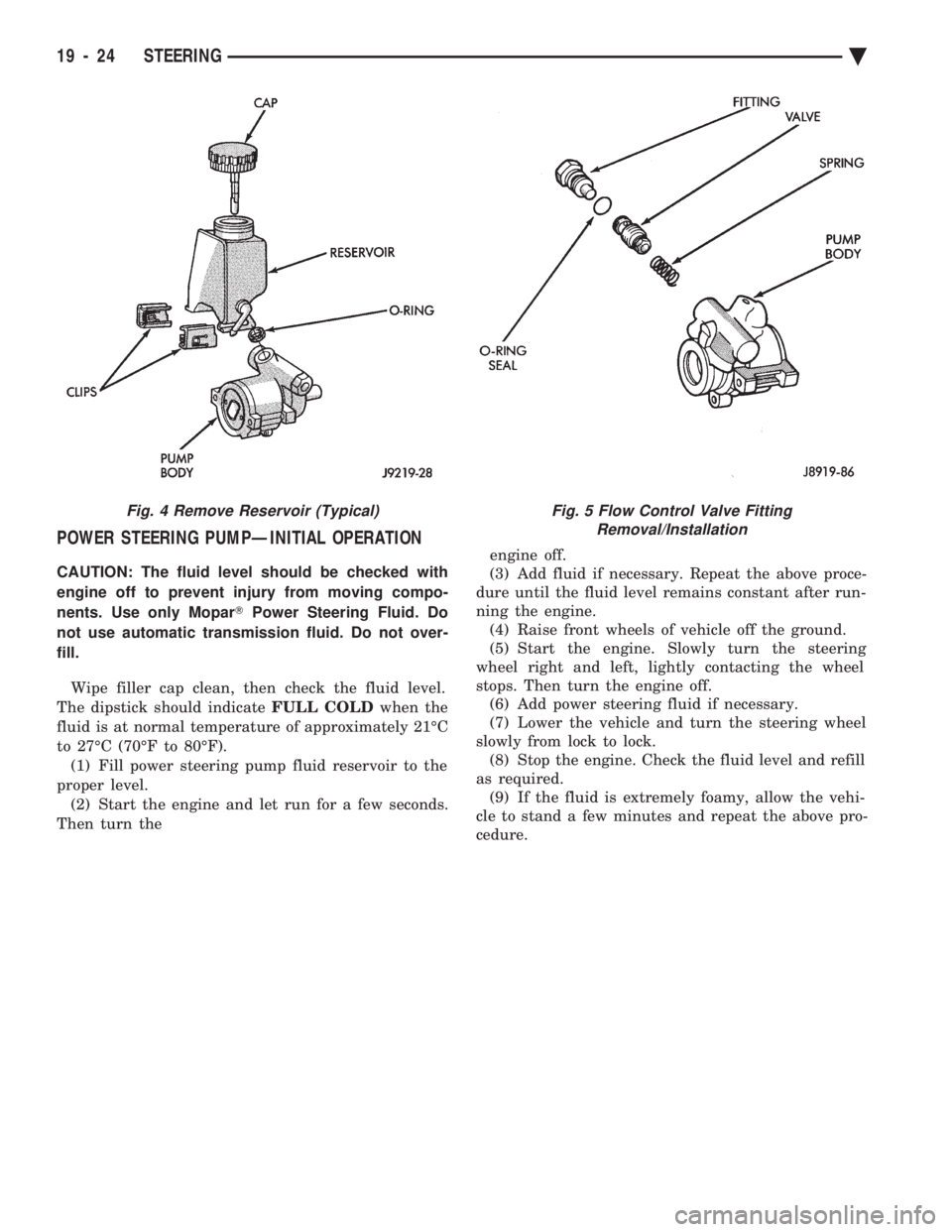
Fig. 4 Remove Reservoir (Typical)Fig. 5 Flow Control Valve Fitting Removal/Installation
19 - 24 STEERING Ä
Page 1992 of 2438
ing seat will give a false end play reading while
gauging for proper shims. Improperly seated bearing
cups and cones are subject to low mileage failure.(2) Bearing cups and cones should be replaced if they
show signs of pitting or heat distress. If distress is seen
on either the cup or bearing rollers, both cup and cone
must be replaced. (3) Bearing preload and drag torque specifications
must be maintained to avoid premature bearing
failures. Used (original) bearing may lose up to 50% of
the original drag torque after break in. All bearing
adjustments must be made with no other compo-
nent interference or gear intermesh. (4) Replace bearings as a pair. For example, if one
differential bearing is defective, replace both differen-
tial bearings. If one input shaft bearing is defective,
replace both input shaft bearings. (5) Bearing cones must notbe reused if removed.
(6) Turning torque readings should be obtained
while smoothly rotating in either direction (break-
away reading is not indicative of the true turning
torque). (7) Replace oil baffle, if damaged.
INPUT SHAFT BEARING END PLAY ADJUST-MENT
(1) Using Tool C-4656 with Handle C-4171, press
input shaft front bearing cup slightly forward in case.
Then, using Tool C-4655 with Handle C-4171, press
bearing cup back into case from the front. Properly
position bearing cup, before checking input shaft end
play (see input shaft front bearing cup replace in
Subassembly Recondition section).This step is
not necessary if Tool C-4655 was previously used
to install input shaft front bearing cup in the
case. Also no input shaft shim has been installed
since pressing cup into case. (2) Select a gauging shim which will give 0.025 to
0.254mm (.001 to .010 inch) end play. SUGGESTION:
Measure original shim from input shaft seal retainer and select a shim 0.254mm (.010
inch) thinner than original for the gauging shim.
(3) Install gauging shim on bearing cup and install
input shaft seal retainer.
CAUTION: The input shaft seal retainer is used to
draw the input shaft front bearing cup the proper
distance into the case bore during this step. Alter-
nately tighten input shaft seal retainer bolts until
input shaft seal retainer is bottomed against case.
Tighten bolts to 28 N Im (21 ft. lbs.).
(4) Oil input shaft bearings with SAE 5W-30 engine
oil and install input shaft in case. Install bearing
retainer plate with input shaft rear bearing cup
pressed in and bearing support plate installed. Tighten
all bolts and nuts to 28 N Im (21 ft. lbs.).
(5) Position dial indicator to check input shaft end
play. Apply moderate load, by hand, to input shaft
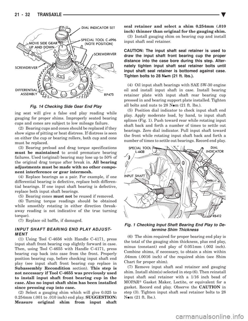
splines (Fig. 1). Push toward rear while rotating input
shaft back and forth a number of times to settle out
bearings. Zero dial indicator. Pull input shaft toward
the front while rotating input shaft back and forth a
number of times to settle out bearings. Record end play.
(6) The shim required for proper bearing end play is
the total of the gauging shim thickness, plus end play,
minus (constant) end play of 0.051mm (.002 inch).
Combine shims, if necessary, to obtain a shim within
.04mm (.0016 inch) of the required shim (see Shim
Chart for proper shim). (7) Remove input shaft seal retainer and gauging
shim. Install shim(s) selected in step (6). Then reinstall
input shaft seal retainer with a 1/16 inch bead of
MOPAR tGasket Maker, Loctite, or equivalent for a
gasket. Record end play. Observe the CAUTIONin
step (3). Tighten input shaft seal retainer bolts to 28
N Im (21 ft. lbs.).
Fig. 14 Checking Side Gear End Play
Fig. 1 Checking Input Shaft Bearing End Play to De-
termine Shim Thickness
21 - 32 TRANSAXLE Ä
Page 2048 of 2438
ing to each new reading. This provides the precise
and sophisticated friction element control needed to
make smooth clutch-to-clutch shifts for all gear
changes. The use of overrunning clutches or other
shift quality aids are not required. As with most au-
tomatic transaxles, all shifts involve releasing one el-
ement and applying a different element. In simplified
terms, the upshift logic allows the releasing element
to slip back wards slightly to ensure that it does not
have excess capacity; the apply element is filled until
it begins to make the speed change to the higher
gear; its apply pressure is then controlled to main-
tain the desired rate of speed change until the shift
is complete. The key to providing excellent shift
quality is precision; for example, as mentioned, the
release element for upshifts is allowed to slip back-
wards slightly; the amount of that slip is typically
less than a total of 20 degrees. To achieve that pre-
cision, the transmission control module learns the
characteristics of the particular transaxle that it is
controlling. It learns the release rate of the releasing
element and the apply time of the applying element.
It also learns the rate at which the apply element
builds pressure sufficient to begin making the speed
change. This method achieves more precision than
would be possible with exacting tolerances. It can
also adapt to any changes that occur with age or en-
vironment, for example, altitude, temperature, en-
gine output, etc. For kickdown shifts, the control logic allows the re-
leasing element to slip and then controls the rate at
which the input (and engine) accelerate; when the
lower gear speed is achieved, the releasing element
reapplies to maintain that speed until the apply ele-
ment is filled. This provides quick response since the
engine begins to accelerate immediately and a
smooth torque exchange since the release element
can control the rate of torque increase. This control
can make any powertrain feel more responsive with-
out in creasing harshness. Adaptive controls respond to input speed changes. They compensate for changes in engine or friction el-
ement torque and provide good, consistent shift qual-
ity for the life of the transaxle.
ON-BOARD DIAGNOSTICS
These controls provide comprehensive, on-board
transaxle diagnostics. The information available can
aid in transaxle diagnosis. For example, apply ele-
ment buildup rate indicates solenoid performance.
Also included are self diagnostic functions. Self diag-
nostics allow the technician to test the condition of
the electronic controls. The transmission control
module continuously monitors its critical functions.
It also records any malfunctions, and the number of
engine starts since the last malfunction. This allows
the technician to use the information in the event of
a customer complaint.
41TE TRANSAXLE GENERAL DIAGNOSIS
CAUTION: Before attempting any repair on a 41TE
four speed automatic transaxle, check for diagnos-
tic trouble codes with the DRB II scan tool. Always
use the Powertrain Diagnostic Test Procedure Man-
ual.
Transaxle malfunctions may be caused by these
general conditions:
² Poor engine performance
² Improper adjustments
² Hydraulic malfunctions
² Mechanical malfunctions
² Electronic malfunctions
Diagnosis of these problems should always begin
by checking the easily accessible variables: fluid
level and condition, gearshift cable adjustment. Then
perform a road test to determine if the problem has
been corrected or that more diagnosis is necessary. If
the problem exists after the preliminary tests and
corrections are completed, hydraulic pressure checks
should be performed.
21 - 88 TRANSAXLE Ä
Page 2310 of 2438
HEATER AND A/C PERFORMANCE TESTS
HEATER OUTPUT TEST
PRE-DIAGNOSTIC PREPARATIONS
Review Safety Precautions and Warnings before
performing the following procedures. Check the radiator coolant level, drive belt tension,
and engine vacuum line connections. Also check ra-
diator air flow and radiator fan operation. Start en-
gine and allow to warm up to normal operating
temperature.
WARNING: DO NOT REMOVE RADIATOR CAP
WHEN ENGINE IS HOT, PERSONAL INJURY CAN
RESULT.
If vehicle has been run recently, wait 15 minutes
before removing cap. Place a rag over the cap and
turn it to the first safety stop. Allow pressure to es-
cape through the overflow tube. When the system
stabilizes, remove the cap completely.
MAXIMUM HEATER OUTPUT: TEST AND ACTION
Engine coolant is provided to the heater system by
two 16 mm (5/8 inch inside diameter) heater hoses.
With engine idling at normal running temperature,
set the control to maximum heat, floor, and high
blower setting. Using a test thermometer, check the
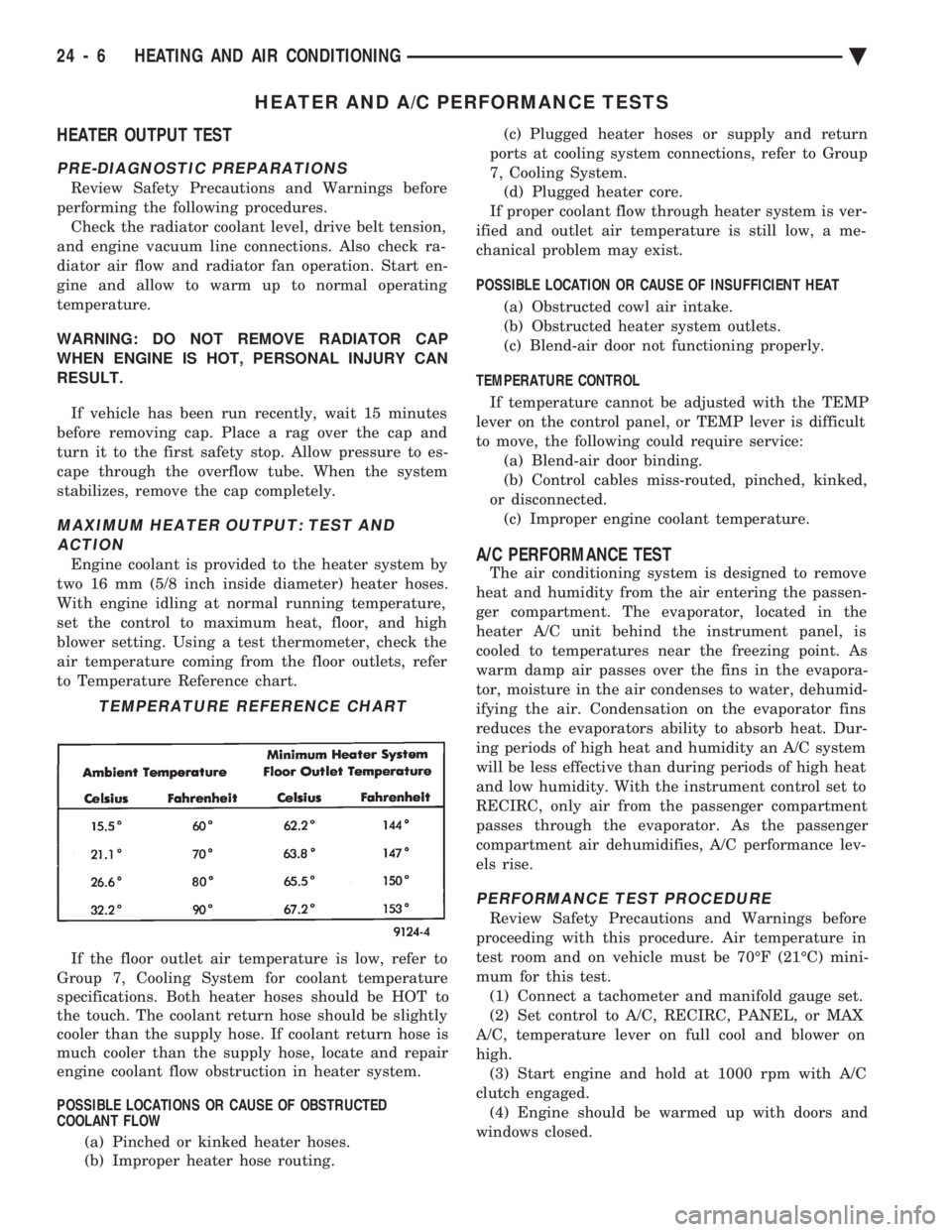
air temperature coming from the floor outlets, refer
to Temperature Reference chart.
If the floor outlet air temperature is low, refer to
Group 7, Cooling System for coolant temperature
specifications. Both heater hoses should be HOT to
the touch. The coolant return hose should be slightly
cooler than the supply hose. If coolant return hose is
much cooler than the supply hose, locate and repair
engine coolant flow obstruction in heater system.
POSSIBLE LOCATIONS OR CAUSE OF OBSTRUCTED
COOLANT FLOW
(a) Pinched or kinked heater hoses.
(b) Improper heater hose routing. (c) Plugged heater hoses or supply and return
ports at cooling system connections, refer to Group
7, Cooling System. (d) Plugged heater core.
If proper coolant flow through heater system is ver-
ified and outlet air temperature is still low, a me-
chanical problem may exist.
POSSIBLE LOCATION OR CAUSE OF INSUFFICIENT HEAT
(a) Obstructed cowl air intake.
(b) Obstructed heater system outlets.
(c) Blend-air door not functioning properly.
TEMPERATURE CONTROL If temperature cannot be adjusted with the TEMP
lever on the control panel, or TEMP lever is difficult
to move, the following could require service: (a) Blend-air door binding.
(b) Control cables miss-routed, pinched, kinked,
or disconnected. (c) Improper engine coolant temperature.A/C PERFORMANCE TEST
The air conditioning system is designed to remove
heat and humidity from the air entering the passen-
ger compartment. The evaporator, located in the
heater A/C unit behind the instrument panel, is
cooled to temperatures near the freezing point. As
warm damp air passes over the fins in the evapora-
tor, moisture in the air condenses to water, dehumid-
ifying the air. Condensation on the evaporator fins
reduces the evaporators ability to absorb heat. Dur-
ing periods of high heat and humidity an A/C system
will be less effective than during periods of high heat
and low humidity. With the instrument control set to
RECIRC, only air from the passenger compartment
passes through the evaporator. As the passenger
compartment air dehumidifies, A/C performance lev-
els rise.
PERFORMANCE TEST PROCEDURE
Review Safety Precautions and Warnings before
proceeding with this procedure. Air temperature in
test room and on vehicle must be 70ÉF (21ÉC) mini-
mum for this test. (1) Connect a tachometer and manifold gauge set.
(2) Set control to A/C, RECIRC, PANEL, or MAX
A/C, temperature lever on full cool and blower on
high. (3) Start engine and hold at 1000 rpm with A/C
clutch engaged. (4) Engine should be warmed up with doors and
windows closed.
TEMPERATURE REFERENCE CHART
24 - 6 HEATING AND AIR CONDITIONING Ä
Page 2312 of 2438
REFRIGERANT SERVICE PROCEDURES INDEX
page page
Adding Partial Refrigerant Charge ............ 10
Charging Refrigerant SystemÐEmpty System . . . 11
Discharging Refrigerant System .............. 11
Evacuating Refrigerant System .............. 11
Manifold Gauge Set Connections ............. 9 Oil Level
............................... 12
R-12 Refrigerant Equipment ................. 8
Refrigerant Recycling ...................... 9
Sight Glass Refrigerant Level Inspection ........ 8
Testing for Refrigerant Leaks ............... 10
SIGHT GLASS REFRIGERANT LEVEL INSPECTION
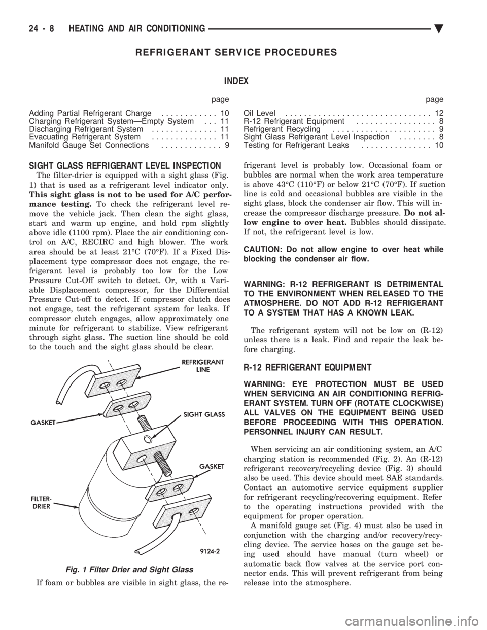
The filter-drier is equipped with a sight glass (Fig.
1) that is used as a refrigerant level indicator only.
This sight glass is not to be used for A/C perfor-
mance testing. To check the refrigerant level re-
move the vehicle jack. Then clean the sight glass,
start and warm up engine, and hold rpm slightly
above idle (1100 rpm). Place the air conditioning con-
trol on A/C, RECIRC and high blower. The work
area should be at least 21ÉC (70ÉF). If a Fixed Dis-
placement type compressor does not engage, the re-
frigerant level is probably too low for the Low
Pressure Cut-Off switch to detect. Or, with a Vari-
able Displacement compressor, for the Differential
Pressure Cut-off to detect. If compressor clutch does
not engage, test the refrigerant system for leaks. If
compressor clutch engages, allow approximately one
minute for refrigerant to stabilize. View refrigerant
through sight glass. The suction line should be cold
to the touch and the sight glass should be clear.
If foam or bubbles are visible in sight glass, the re- frigerant level is probably low. Occasional foam or
bubbles are normal when the work area temperature
is above 43ÉC (110ÉF) or below 21ÉC (70ÉF). If suction
line is cold and occasional bubbles are visible in the
sight glass, block the condenser air flow. This will in-
crease the compressor discharge pressure. Do not al-
low engine to over heat. Bubbles should dissipate.
If not, the refrigerant level is low.
CAUTION: Do not allow engine to over heat while
blocking the condenser air flow.
WARNING: R-12 REFRIGERANT IS DETRIMENTAL
TO THE ENVIRONMENT WHEN RELEASED TO THE
ATMOSPHERE. DO NOT ADD R-12 REFRIGERANT
TO A SYSTEM THAT HAS A KNOWN LEAK.
The refrigerant system will not be low on (R-12)
unless there is a leak. Find and repair the leak be-
fore charging.
R-12 REFRIGERANT EQUIPMENT
WARNING: EYE PROTECTION MUST BE USED
WHEN SERVICING AN AIR CONDITIONING REFRIG-
ERANT SYSTEM. TURN OFF (ROTATE CLOCKWISE)
ALL VALVES ON THE EQUIPMENT BEING USED
BEFORE PROCEEDING WITH THIS OPERATION.
PERSONNEL INJURY CAN RESULT.
When servicing an air conditioning system, an A/C
charging station is recommended (Fig. 2). An (R-12)
refrigerant recovery/recycling device (Fig. 3) should
also be used. This device should meet SAE standards.
Contact an automotive service equipment supplier
for refrigerant recycling/recovering equipment. Refer
to the operating instructions provided with the
equipment for proper operation. A manifold gauge set (Fig. 4) must also be used in
conjunction with the charging and/or recovery/recy-
cling device. The service hoses on the gauge set be-
ing used should have manual (turn wheel) or
automatic back flow valves at the service port con-
nector ends. This will prevent refrigerant from being
release into the atmosphere.
Fig. 1 Filter Drier and Sight Glass
24 - 8 HEATING AND AIR CONDITIONING Ä