1993 CHEVROLET DYNASTY check engine light
[x] Cancel search: check engine lightPage 1605 of 2438
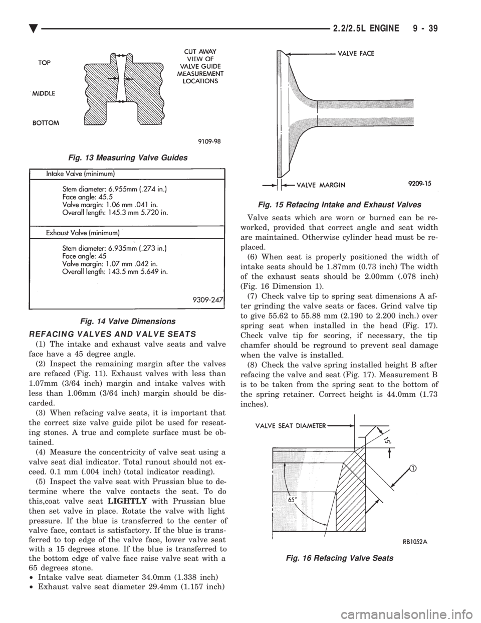
REFACING VALVES AND VALVE SEATS
(1) The intake and exhaust valve seats and valve
face have a 45 degree angle. (2) Inspect the remaining margin after the valves
are refaced (Fig. 11). Exhaust valves with less than
1.07mm (3/64 inch) margin and intake valves with
less than 1.06mm (3/64 inch) margin should be dis-
carded. (3) When refacing valve seats, it is important that
the correct size valve guide pilot be used for reseat-
ing stones. A true and complete surface must be ob-
tained. (4) Measure the concentricity of valve seat using a
valve seat dial indicator. Total runout should not ex-
ceed. 0.1 mm (.004 inch) (total indicator reading). (5) Inspect the valve seat with Prussian blue to de-
termine where the valve contacts the seat. To do
this,coat valve seat LIGHTLYwith Prussian blue
then set valve in place. Rotate the valve with light
pressure. If the blue is transferred to the center of
valve face, contact is satisfactory. If the blue is trans-
ferred to top edge of the valve face, lower valve seat
with a 15 degrees stone. If the blue is transferred to
the bottom edge of valve face raise valve seat with a
65 degrees stone.
² Intake valve seat diameter 34.0mm (1.338 inch)
² Exhaust valve seat diameter 29.4mm (1.157 inch) Valve seats which are worn or burned can be re-
worked, provided that correct angle and seat width
are maintained. Otherwise cylinder head must be re-
placed. (6) When seat is properly positioned the width of
intake seats should be 1.87mm (0.73 inch) The width
of the exhaust seats should be 2.00mm (.078 inch)
(Fig. 16 Dimension 1). (7) Check valve tip to spring seat dimensions A af-
ter grinding the valve seats or faces. Grind valve tip
to give 55.62 to 55.88 mm (2.190 to 2.200 inch.) over
spring seat when installed in the head (Fig. 17).
Check valve tip for scoring, if necessary, the tip
chamfer should be reground to prevent seal damage
when the valve is installed. (8) Check the valve spring installed height B after
refacing the valve and seat (Fig. 17). Measurement B
is to be taken from the spring seat to the bottom of
the spring retainer. Correct height is 44.0mm (1.73
inches).
Fig. 13 Measuring Valve Guides
Fig. 14 Valve Dimensions
Fig. 15 Refacing Intake and Exhaust Valves
Fig. 16 Refacing Valve Seats
Ä 2.2/2.5L ENGINE 9 - 39
Page 1609 of 2438
CRANKSHAFT SERVICE
CRANKSHAFT MAIN BEARINGS
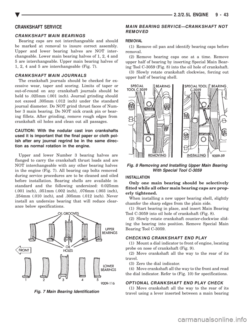
Bearing caps are not interchangeable and should
be marked at removal to insure correct assembly.
Upper and lower bearing halves are NOT inter-
changeable. Lower main bearing halves of 1, 2, 4 and
5 are interchangeable. Upper main bearing halves of
1, 2, 4 and 5 are interchangeable (Fig. 7).
CRANKSHAFT MAIN JOURNALS
The crankshaft journals should be checked for ex-
cessive wear, taper and scoring. Limits of taper or
out-of-round on any crankshaft journals should be
held to .025mm (.001 inch). Journal grinding should
not exceed .305mm (.012 inch) under the standard
journal diameter. Do NOT grind thrust faces of Num-
ber 3 main bearing. Do NOT nick crank pin or bear-
ing fillets. After grinding, remove rough edges from
crankshaft oil holes and clean out all passages.
CAUTION: With the nodular cast iron crankshafts
used it is important that the final paper or cloth pol-
ish after any journal regrind be in the same direc-
tion as normal rotation in the engine.
Upper and lower Number 3 bearing halves are
flanged to carry the crankshaft thrust loads and are
NOT interchangeable with any other bearing halves
in the engine (Fig. 7). All bearing cap bolts removed
during service procedures are to be cleaned and oiled
before installation. Bearing shells are available in
standard and the following undersized: 0.025mm
(.001 inch), .051mm (.002 inch), .076mm (.003 inch),
.254mm (.010 inch), and .305mm (.012 inch). Never
install an undersize bearing that will reduce clear-
ance below specifications.
MAIN BEARING SERVICEÐCRANKSHAFT NOT REMOVED
REMOVAL
(1) Remove oil pan and identify bearing caps before
removal. (2) Remove bearing caps one at a time. Remove
upper half of bearing by inserting Special Main Bear-
ing Tool C-3059 (Fig. 8) into the oil hole of crankshaft. (3) Slowly rotate crankshaft clockwise, forcing out
upper half of bearing shell.
INSTALLATION Only one main bearing should be selectively
fitted while all other main bearing caps are prop-
erly tightened. When installing a new upper bearing shell, slightly
chamfer the sharp edges from the plain side. (1) Start bearing in place, and insert Main Bearing
Tool C-3059 into oil hole of crankshaft (Fig. 8). (2) Slowly rotate crankshaft counter-clockwise slid-
ing the bearing into position. Remove Special Main
Bearing Tool C-3059.
CHECKING CRANKSHAFT END PLAY
(1) Mount a dial indicator to front of engine, locating
probe on nose of crankshaft (Fig. 9). (2) Move crankshaft all the way to the rear of its
travel. (3) Zero the dial indicator.
(4) Move crankshaft all the way to the front and read
the dial indicator. Refer to (Fig. 10) for specifications.
OPTIONAL CRANKSHAFT END PLAY CHECK
(1) Move crankshaft all the way to the rear of its
travel using a lever inserted between a main bearingFig. 7 Main Bearing Identification
Fig. 8 Removing and Installing Upper Main Bearing With Special Tool C-3059
Ä 2.2/2.5L ENGINE 9 - 43
Page 1618 of 2438
PISTON PINS
DISASSEMBLY Turbo III engine piston-pin-connecting rod assem-
blies should not be disassembled unless a malfunc-
tion is present or a damaged assembly component is
to be replaced. WARNING: APPROVED SAFETY GLASSES
MUST BE WORN DURING PISTON LOCK
RING REMOVAL OR INSTALLATION TO PRE-
VENT POSSIBLE INJURY FROM FLYING
PARTS.
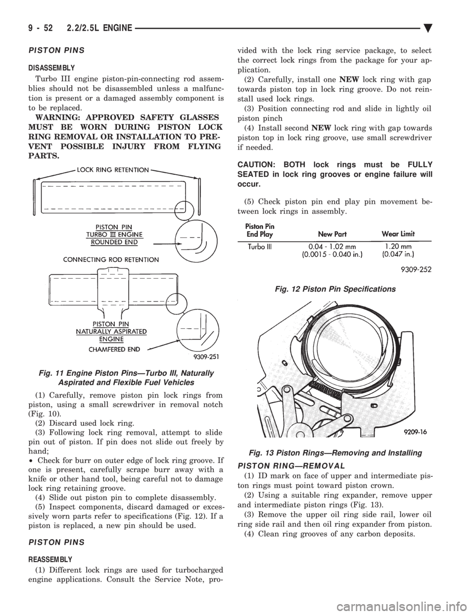
(1) Carefully, remove piston pin lock rings from
piston, using a small screwdriver in removal notch
(Fig. 10). (2) Discard used lock ring.
(3) Following lock ring removal, attempt to slide
pin out of piston. If pin does not slide out freely by
hand;
² Check for burr on outer edge of lock ring groove. If
one is present, carefully scrape burr away with a
knife or other hand tool, being careful not to damage
lock ring retaining groove. (4) Slide out piston pin to complete disassembly.
(5) Inspect components, discard damaged or exces-
sively worn parts refer to specifications (Fig. 12). If a
piston is replaced, a new pin should be used.
PISTON PINS
REASSEMBLY
(1) Different lock rings are used for turbocharged
engine applications. Consult the Service Note, pro- vided with the lock ring service package, to select
the correct lock rings from the package for your ap-
plication.
(2) Carefully, install one NEWlock ring with gap
towards piston top in lock ring groove. Do not rein-
stall used lock rings. (3) Position connecting rod and slide in lightly oil
piston pinch (4) Install second NEWlock ring with gap towards
piston top in lock ring groove, use small screwdriver
if needed.
CAUTION: BOTH lock rings must be FULLY
SEATED in lock ring grooves or engine failure will
occur.
(5) Check piston pin end play pin movement be-
tween lock rings in assembly.
PISTON RINGÐREMOVAL
(1) ID mark on face of upper and intermediate pis-
ton rings must point toward piston crown. (2) Using a suitable ring expander, remove upper
and intermediate piston rings (Fig. 13). (3) Remove the upper oil ring side rail, lower oil
ring side rail and then oil ring expander from piston. (4) Clean ring grooves of any carbon deposits.
Fig. 11 Engine Piston PinsÐTurbo III, Naturally Aspirated and Flexible Fuel Vehicles
Fig. 12 Piston Pin Specifications
Fig. 13 Piston RingsÐRemoving and Installing
9 - 52 2.2/2.5L ENGINE Ä
Page 1621 of 2438
CONNECTING RODS
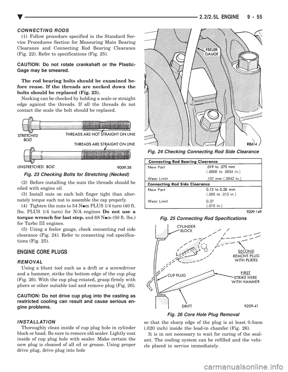
(1) Follow procedure specified in the Standard Ser-
vice Procedures Section for Measuring Main Bearing
Clearance and Connecting Rod Bearing Clearance
(Fig. 22). Refer to specifications (Fig. 25).
CAUTION: Do not rotate crankshaft or the Plastic-
Gage may be smeared.
The rod bearing bolts should be examined be-
fore reuse. If the threads are necked down the
bolts should be replaced (Fig. 23). Necking can be checked by holding a scale or straight
edge against the threads. If all the threads do not
contact the scale the bolt should be replaced.
(2) Before installing the nuts the threads should be
oiled with engine oil.
(3) Install nuts on each bolt finger tight than alter-
nately torque each nut to assemble the cap properly.
(4) Tighten the nuts to 54 N Im PLUS 1/4 turn (40 ft.
lbs. PLUS 1/4 turn) for N/A engines Do not use a
torque wrench for last step. and 68 NIm (50 ft. lbs.)
for Turbo III engines. (5) Using a feeler gauge, check connecting rod side
clearance (Fig. 24). Refer to connecting rod specifica-
tions (Fig. 25).
ENGINE CORE PLUGS
REMOVAL
Using a blunt tool such as a drift or a screwdriver
and a hammer, strike the bottom edge of the cup plug
(Fig. 26). With the cup plug rotated, grasp firmly with
pliers or other suitable tool and remove plug (Fig. 26).
CAUTION: Do not drive cup plug into the casting as
restricted cooling can result and cause serious en-
gine problems.
INSTALLATION
Thoroughly clean inside of cup plug hole in cylinder
block or head. Be sure to remove old sealer. Lightly coat
inside of cup plug hole with sealer. Make certain the
new plug is cleaned of all oil or grease. Using proper
drive plug, drive plug into hole so that the sharp edge of the plug is at least 0.5mm
(.020 inch) inside the lead-in chamfer (Fig. 26).
It is in not necessary to wait for curing of the seal-
ant. The cooling system can be refilled and the vehi-
cle placed in service immediately.
Fig. 24 Checking Connecting Rod Side Clearance
Fig. 25 Connecting Rod Specifications
Fig. 26 Core Hole Plug Removal
Fig. 23 Checking Bolts for Stretching (Necked)
Ä 2.2/2.5L ENGINE 9 - 55
Page 1632 of 2438
3.0L ENGINE INDEX
page page
Accessory Drive Belt Service ................ 70
Auto Lash Adjuster ....................... 75
Camshaft Service ........................ 76
Checking Engine Oil Pressure ............... 93
Crankshaft and Cylinder Block, Assembly Service . 86
Cylinder Block ........................... 89
Cylinder Head ........................... 78
Cylinder Head and Camshaft Service ......... 75
Engine Assembly ......................... 69
Engine Lubrication System ................. 91
Engine Mounts .......................... 68 Engine Specifications
..................... 95
General Information ....................... 66
Oil Filter and Bracket ..................... 94
Oil Pan ................................ 92
Oil Pump Service ........................ 92
Piston and Connecting Rod Assembly Service . . . 82
Timing Belt InspectionÐIn Vehicle ............ 72
Timing Belt Service ....................... 72
Valve Service ........................... 80
GENERAL INFORMATION
ENGINE IDENTIFICATION NUMBER OR CODE
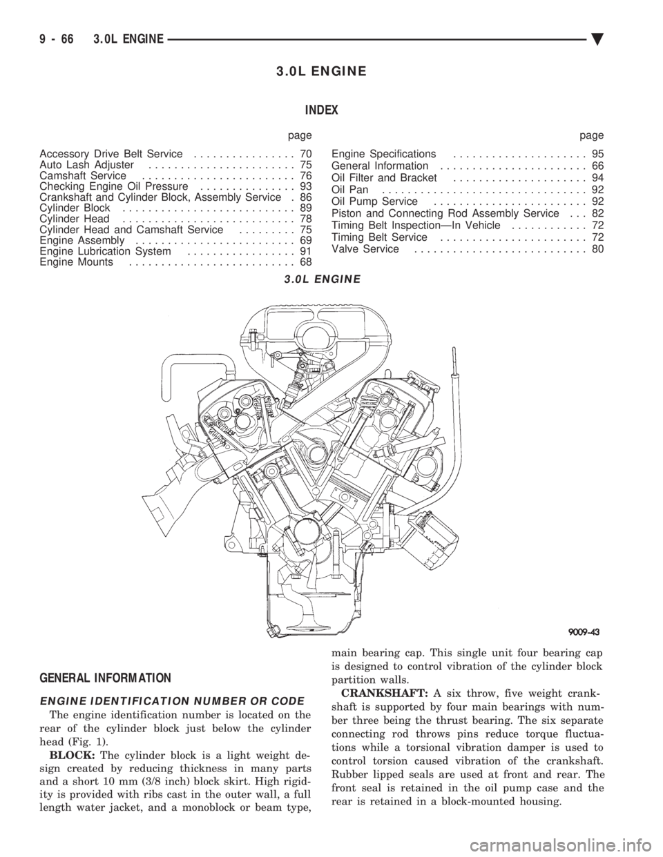
The engine identification number is located on the
rear of the cylinder block just below the cylinder
head (Fig. 1). BLOCK: The cylinder block is a light weight de-
sign created by reducing thickness in many parts
and a short 10 mm (3/8 inch) block skirt. High rigid-
ity is provided with ribs cast in the outer wall, a full
length water jacket, and a monoblock or beam type, main bearing cap. This single unit four bearing cap
is designed to control vibration of the cylinder block
partition walls.
CRANKSHAFT: A six throw, five weight crank-
shaft is supported by four main bearings with num-
ber three being the thrust bearing. The six separate
connecting rod throws pins reduce torque fluctua-
tions while a torsional vibration damper is used to
control torsion caused vibration of the crankshaft.
Rubber lipped seals are used at front and rear. The
front seal is retained in the oil pump case and the
rear is retained in a block-mounted housing.
3.0L ENGINE
9 - 66 3.0L ENGINE Ä
Page 1641 of 2438
CYLINDER HEAD AND CAMSHAFT SERVICE
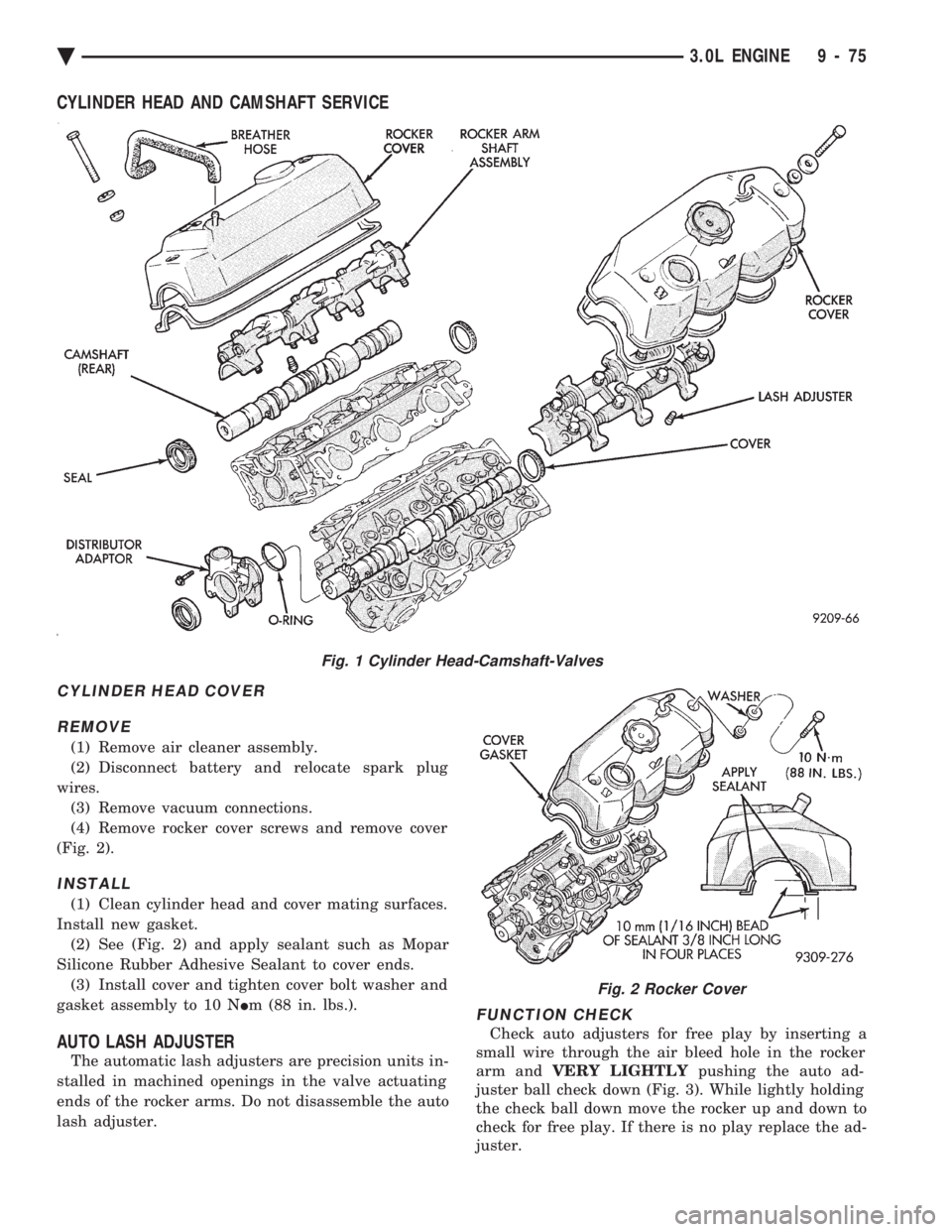
CYLINDER HEAD COVER REMOVE
(1) Remove air cleaner assembly.
(2) Disconnect battery and relocate spark plug
wires. (3) Remove vacuum connections.
(4) Remove rocker cover screws and remove cover
(Fig. 2).
INSTALL
(1) Clean cylinder head and cover mating surfaces.
Install new gasket. (2) See (Fig. 2) and apply sealant such as Mopar
Silicone Rubber Adhesive Sealant to cover ends. (3) Install cover and tighten cover bolt washer and
gasket assembly to 10 N Im (88 in. lbs.).
AUTO LASH ADJUSTER
The automatic lash adjusters are precision units in-
stalled in machined openings in the valve actuating
ends of the rocker arms. Do not disassemble the auto
lash adjuster.
FUNCTION CHECK
Check auto adjusters for free play by inserting a
small wire through the air bleed hole in the rocker
arm and VERY LIGHTLY pushing the auto ad-
juster ball check down (Fig. 3). While lightly holding
the check ball down move the rocker up and down to
check for free play. If there is no play replace the ad-
juster.
Fig. 1 Cylinder Head-Camshaft-Valves
Fig. 2 Rocker Cover
Ä 3.0L ENGINE 9 - 75
Page 1643 of 2438
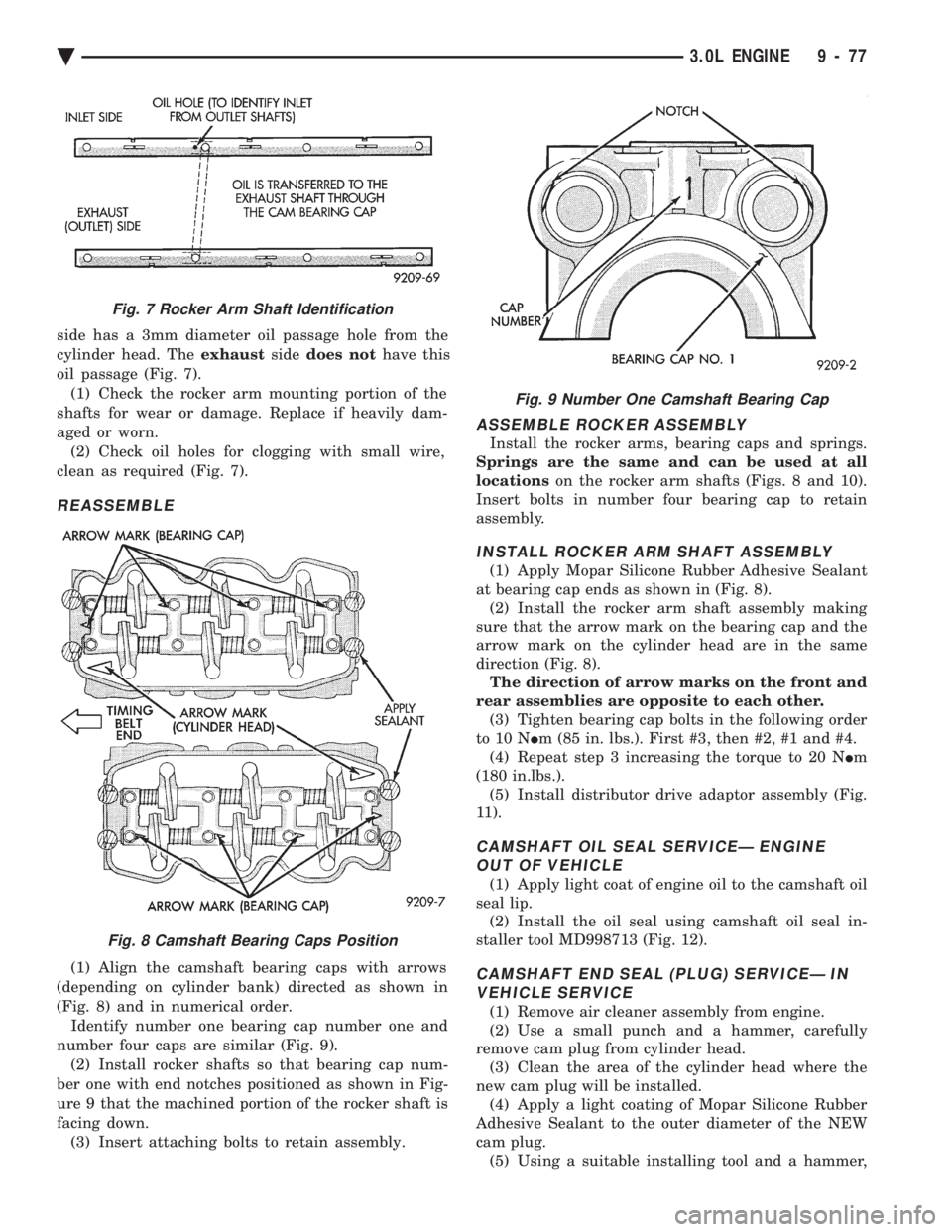
side has a 3mm diameter oil passage hole from the
cylinder head. The exhaustsidedoes not have this
oil passage (Fig. 7). (1) Check the rocker arm mounting portion of the
shafts for wear or damage. Replace if heavily dam-
aged or worn. (2) Check oil holes for clogging with small wire,
clean as required (Fig. 7).
REASSEMBLE
(1) Align the camshaft bearing caps with arrows
(depending on cylinder bank) directed as shown in
(Fig. 8) and in numerical order. Identify number one bearing cap number one and
number four caps are similar (Fig. 9). (2) Install rocker shafts so that bearing cap num-
ber one with end notches positioned as shown in Fig-
ure 9 that the machined portion of the rocker shaft is
facing down. (3) Insert attaching bolts to retain assembly.
ASSEMBLE ROCKER ASSEMBLY
Install the rocker arms, bearing caps and springs.
Springs are the same and can be used at all
locations on the rocker arm shafts (Figs. 8 and 10).
Insert bolts in number four bearing cap to retain
assembly.
INSTALL ROCKER ARM SHAFT ASSEMBLY
(1) Apply Mopar Silicone Rubber Adhesive Sealant
at bearing cap ends as shown in (Fig. 8). (2) Install the rocker arm shaft assembly making
sure that the arrow mark on the bearing cap and the
arrow mark on the cylinder head are in the same
direction (Fig. 8). The direction of arrow marks on the front and
rear assemblies are opposite to each other. (3) Tighten bearing cap bolts in the following order
to 10 N Im (85 in. lbs.). First #3, then #2, #1 and #4.
(4) Repeat step 3 increasing the torque to 20 N Im
(180 in.lbs.). (5) Install distributor drive adaptor assembly (Fig.
11).
CAMSHAFT OIL SEAL SERVICEÐ ENGINE OUT OF VEHICLE
(1) Apply light coat of engine oil to the camshaft oil
seal lip. (2) Install the oil seal using camshaft oil seal in-
staller tool MD998713 (Fig. 12).
CAMSHAFT END SEAL (PLUG) SERVICEÐ IN VEHICLE SERVICE
(1) Remove air cleaner assembly from engine.
(2) Use a small punch and a hammer, carefully
remove cam plug from cylinder head. (3) Clean the area of the cylinder head where the
new cam plug will be installed. (4) Apply a light coating of Mopar Silicone Rubber
Adhesive Sealant to the outer diameter of the NEW
cam plug. (5) Using a suitable installing tool and a hammer,
Fig. 7 Rocker Arm Shaft Identification
Fig. 8 Camshaft Bearing Caps Position
Fig. 9 Number One Camshaft Bearing Cap
Ä 3.0L ENGINE 9 - 77
Page 1646 of 2438
INSTALLATION
(1) Clean surfaces of head and block, install head
gasket over locating dowels. (2) Install head on locating dowels.
(3) Install 10mm allen hex head bolts with wash-
ers. (4) Tighten bolts in the order shown in (Fig. 16).
When tightening the cylinder head bolts, tighten
gradually, working in two or three steps and finally
tighten to specified torque of 108 N Im (80 ft. lbs.).
VALVE SERVICE
VALVE AND VALVE SPRINGS
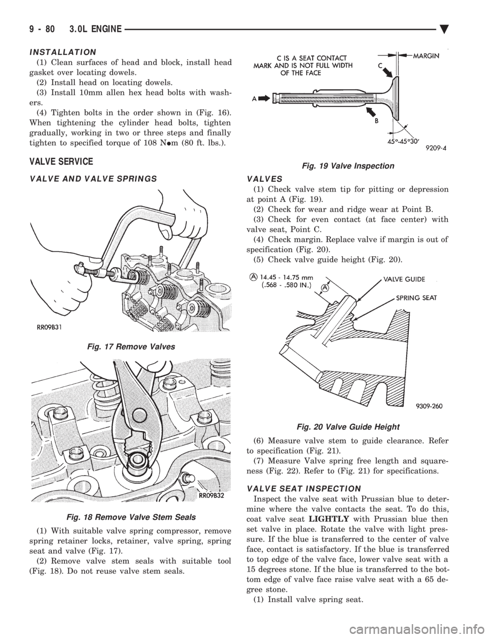
(1) With suitable valve spring compressor, remove
spring retainer locks, retainer, valve spring, spring
seat and valve (Fig. 17). (2) Remove valve stem seals with suitable tool
(Fig. 18). Do not reuse valve stem seals.
VALVES
(1) Check valve stem tip for pitting or depression
at point A (Fig. 19). (2) Check for wear and ridge wear at Point B.
(3) Check for even contact (at face center) with
valve seat, Point C. (4) Check margin. Replace valve if margin is out of
specification (Fig. 20). (5) Check valve guide height (Fig. 20).
(6) Measure valve stem to guide clearance. Refer
to specification (Fig. 21). (7) Measure Valve spring free length and square-
ness (Fig. 22). Refer to (Fig. 21) for specifications.
VALVE SEAT INSPECTION
Inspect the valve seat with Prussian blue to deter-
mine where the valve contacts the seat. To do this,
coat valve seat LIGHTLYwith Prussian blue then
set valve in place. Rotate the valve with light pres-
sure. If the blue is transferred to the center of valve
face, contact is satisfactory. If the blue is transferred
to top edge of the valve face, lower valve seat with a
15 degrees stone. If the blue is transferred to the bot-
tom edge of valve face raise valve seat with a 65 de-
gree stone. (1) Install valve spring seat.
Fig. 17 Remove Valves
Fig. 18 Remove Valve Stem Seals
Fig. 19 Valve Inspection
Fig. 20 Valve Guide Height
9 - 80 3.0L ENGINE Ä