1993 CHEVROLET DYNASTY check engine light
[x] Cancel search: check engine lightPage 539 of 2438
(3) With the ignition switch ON, an open (discon-
nected sending unit wire) causes the oil, fuel or tem-
perature gauge to read below low, empty or cold
indicators. (4) If steps 2 and 3 check OK, refer to the individ-
ual sending unit test procedures.
FUEL TANK SENDING UNIT TEST
Refer to Group 14, Fuel for test procedure.
CHECK GAUGES WARNING LAMP TESTS
The check gauges warning lamp will illuminated
when the ignition key is turned to the ON position.
The lamp will illuminate if the engine oil pressure
drops below a safe level. The check gauge lamp will
light for high engine temperature or for low voltage. To test the system turn ignition key to the ON po-
sition. If the lamp fails to light, inspect for a broken
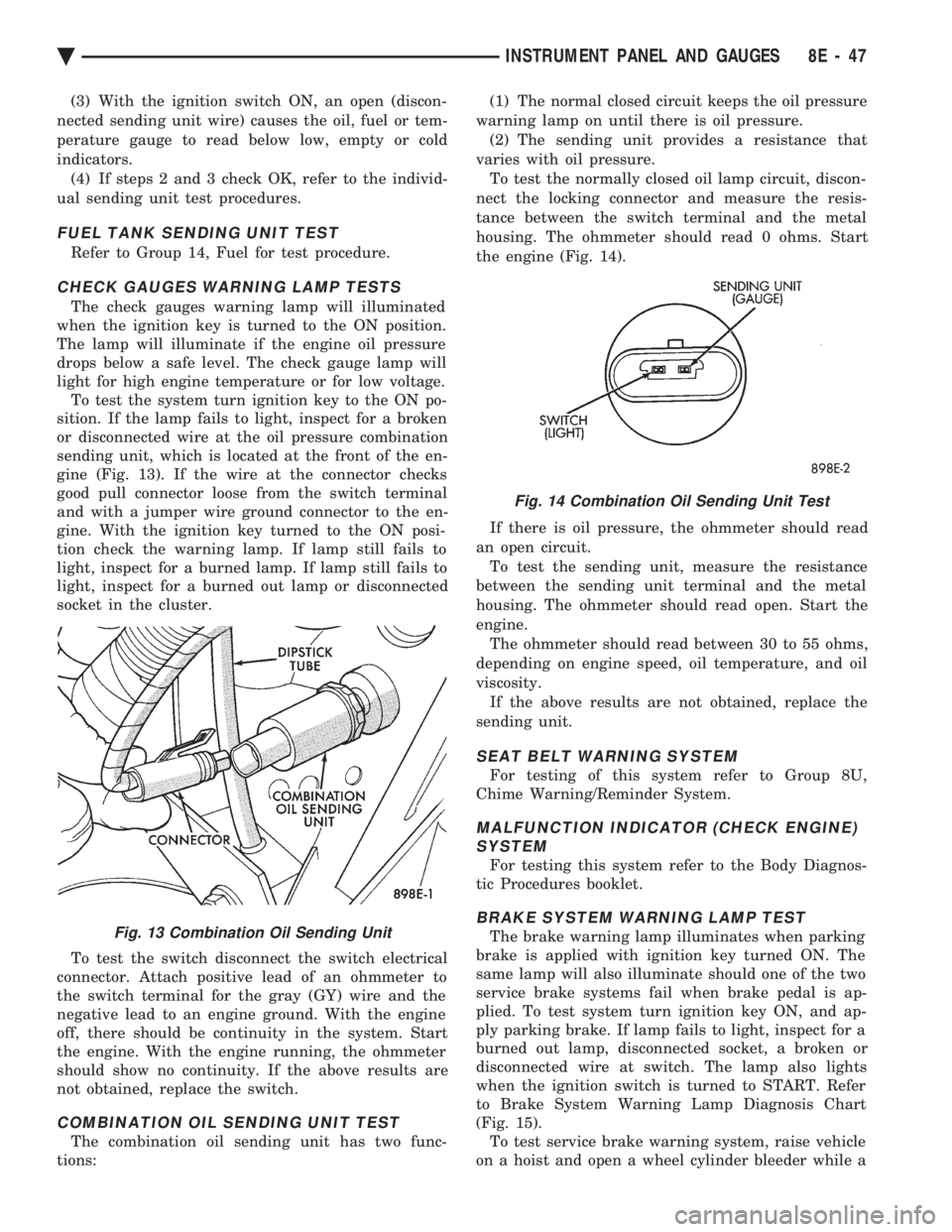
or disconnected wire at the oil pressure combination
sending unit, which is located at the front of the en-
gine (Fig. 13). If the wire at the connector checks
good pull connector loose from the switch terminal
and with a jumper wire ground connector to the en-
gine. With the ignition key turned to the ON posi-
tion check the warning lamp. If lamp still fails to
light, inspect for a burned lamp. If lamp still fails to
light, inspect for a burned out lamp or disconnected
socket in the cluster.
To test the switch disconnect the switch electrical
connector. Attach positive lead of an ohmmeter to
the switch terminal for the gray (GY) wire and the
negative lead to an engine ground. With the engine
off, there should be continuity in the system. Start
the engine. With the engine running, the ohmmeter
should show no continuity. If the above results are
not obtained, replace the switch.
COMBINATION OIL SENDING UNIT TEST
The combination oil sending unit has two func-
tions: (1) The normal closed circuit keeps the oil pressure
warning lamp on until there is oil pressure. (2) The sending unit provides a resistance that
varies with oil pressure. To test the normally closed oil lamp circuit, discon-
nect the locking connector and measure the resis-
tance between the switch terminal and the metal
housing. The ohmmeter should read 0 ohms. Start
the engine (Fig. 14).
If there is oil pressure, the ohmmeter should read
an open circuit. To test the sending unit, measure the resistance
between the sending unit terminal and the metal
housing. The ohmmeter should read open. Start the
engine. The ohmmeter should read between 30 to 55 ohms,
depending on engine speed, oil temperature, and oil
viscosity. If the above results are not obtained, replace the
sending unit.
SEAT BELT WARNING SYSTEM
For testing of this system refer to Group 8U,
Chime Warning/Reminder System.
MALFUNCTION INDICATOR (CHECK ENGINE) SYSTEM
For testing this system refer to the Body Diagnos-
tic Procedures booklet.
BRAKE SYSTEM WARNING LAMP TEST
The brake warning lamp illuminates when parking
brake is applied with ignition key turned ON. The
same lamp will also illuminate should one of the two
service brake systems fail when brake pedal is ap-
plied. To test system turn ignition key ON, and ap-
ply parking brake. If lamp fails to light, inspect for a
burned out lamp, disconnected socket, a broken or
disconnected wire at switch. The lamp also lights
when the ignition switch is turned to START. Refer
to Brake System Warning Lamp Diagnosis Chart
(Fig. 15). To test service brake warning system, raise vehicle
on a hoist and open a wheel cylinder bleeder while aFig. 13 Combination Oil Sending Unit
Fig. 14 Combination Oil Sending Unit Test
Ä INSTRUMENT PANEL AND GAUGES 8E - 47
Page 540 of 2438

helper depresses brake pedal and observes warning
lamp. If lamp fails to light, inspect for a burned out
lamp, disconnected socket, a broken or disconnected
wire at switch.If lamp is not burned out and wire continuity is
proven, replace brake warning switch in brake line
TEE fitting mounted on frame rail in engine com-
partment below master cylinder (Fig.16).
CAUTION: If wheel cylinder bleeder was opened
check master cylinder fluid level.
SPEEDOMETER SYSTEM
The vehicles are equipped with electronically
driven speedometer and odometer assemblies. The
unit has the same appearance as a conventional
speedometer but it eliminates the cable-driven me-
chanical system. A signal is sent from a transmis-
sion-mounted vehicle speed sensor to the
speedometer circuitry through the wiring harness.
By eliminating the speedometer cable, instrument
cluster service and removal is improved. Refer to Fig.
17 Speedometer Diagnosis Chart. When the speedometer is out of calibration. The
electronic automatic transaxle vehicle speed sensor
output must be calibrated to reflect the different combinations of equipment. The procedure is called
Pinion Factor, refer to Group 21, Transaxle for the
procedure.
Fig. 15 Brake System Warning Lamp Diagnosis
Fig. 16 Brake Warning Lamp Switch
8E - 48 INSTRUMENT PANEL AND GAUGES Ä
Page 550 of 2438

AP BODY INDEX
page page
Cluster and Gauge Service and Testing ....... 58
Gauges ................................ 61
General Information ....................... 58 Instrument Panel Replacement
.............. 72
Interior Lamp Replacement ................. 73
Switch and Panel Component Service ......... 67
GENERAL INFORMATION
INSTRUMENT CLUSTER
There are two conventional instrument cluster as-
semblies available. The clusters incorporates mag-
netic type gauges and an electronically driven
speedometer and odometer assembly (Fig. 1 and 2).
MAGNETIC GAUGES
All gauges on the AP Body clusters are the mag-
netic type gauges. When the ignition switch is in the
OFF position each gauge, except for the voltmeter
and tachometer will show a reading. However, the
readings are only accurate when the ignition switch
is in the ON position.
TACHOMETER DRIVE MODULE
The tachometer drive module is an electronic mod-
ule used to drive the magnetic tachometer in the
high line cluster. This module is located on top of the instrument
cluster.
ELECTRONIC DIGITAL CLOCK
The electronic digital clock is in the radio. The
clock and radio each use the display panel built into
the radio. A digital readout indicates the time in
hours and minutes whenever the ignition switch is in
the ON or ACC position. When the ignition switch is in the OFF position, or
when the radio frequency is being displayed, time
keeping is accurately maintained. The procedure for setting the clock varies slightly
with each radio. The correct procedure is described
under the individual radio operating instructions re-
fer to the Sound Systems Manual supplied with the
vehicle.
WARNING LAMPS AND INDICATOR LIGHTS
The instrument cluster has warning and indicators
lamps for eight different systems:
² Low oil pressure
² Brake warning
² Seat belt warning
² Malfunction indicator (check engine) lamp
² Air Bag
² High beam indicator
² Right and left turn signals.
² Anti-lock (ABS)
CLUSTER AND GAUGE SERVICE AND TESTING
CAUTION: Disconnect the negative battery cable
before servicing the instrument panel. When power
is required for test purposes, reconnect battery ca-
ble for test only. Disconnect the negative battery
cable after test and before continuing service pro-
cedures.
SENDING UNIT TEST
Check for a defective sending unit or wiring, when
a problem occurs with a cluster gauge. Do this before
disassembling the cluster. (1) Sending units and wiring can be checked by
grounding the connector leads, at the sending unit,
in the vehicle. (2) With the ignition in the ON position, a
grounded input will cause the fuel or temperature
gauge to read at or above maximum.
Fig. 1 Instrument Cluster With Tachometer
Fig. 2 Instrument Cluster Without Tachometer
8E - 58 INSTRUMENT PANEL AND GAUGES Ä
Page 551 of 2438
FUEL TANK SENDING UNIT TEST
Refer to Group 14, Fuel for test procedures.
LOW OIL PRESSURE WARNING LAMP TEST
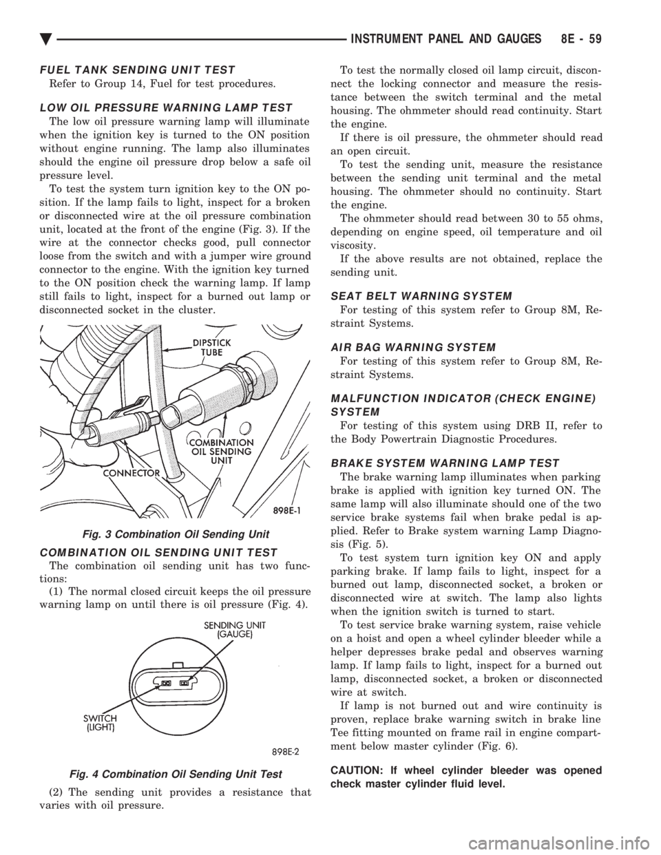
The low oil pressure warning lamp will illuminate
when the ignition key is turned to the ON position
without engine running. The lamp also illuminates
should the engine oil pressure drop below a safe oil
pressure level. To test the system turn ignition key to the ON po-
sition. If the lamp fails to light, inspect for a broken
or disconnected wire at the oil pressure combination
unit, located at the front of the engine (Fig. 3). If the
wire at the connector checks good, pull connector
loose from the switch and with a jumper wire ground
connector to the engine. With the ignition key turned
to the ON position check the warning lamp. If lamp
still fails to light, inspect for a burned out lamp or
disconnected socket in the cluster.
COMBINATION OIL SENDING UNIT TEST
The combination oil sending unit has two func-
tions: (1) The normal closed circuit keeps the oil pressure
warning lamp on until there is oil pressure (Fig. 4).
(2) The sending unit provides a resistance that
varies with oil pressure. To test the normally closed oil lamp circuit, discon-
nect the locking connector and measure the resis-
tance between the switch terminal and the metal
housing. The ohmmeter should read continuity. Start
the engine. If there is oil pressure, the ohmmeter should read
an open circuit. To test the sending unit, measure the resistance
between the sending unit terminal and the metal
housing. The ohmmeter should no continuity. Start
the engine. The ohmmeter should read between 30 to 55 ohms,
depending on engine speed, oil temperature and oil
viscosity. If the above results are not obtained, replace the
sending unit.
SEAT BELT WARNING SYSTEM
For testing of this system refer to Group 8M, Re-
straint Systems.
AIR BAG WARNING SYSTEM
For testing of this system refer to Group 8M, Re-
straint Systems.
MALFUNCTION INDICATOR (CHECK ENGINE) SYSTEM
For testing of this system using DRB II, refer to
the Body Powertrain Diagnostic Procedures.
BRAKE SYSTEM WARNING LAMP TEST
The brake warning lamp illuminates when parking
brake is applied with ignition key turned ON. The
same lamp will also illuminate should one of the two
service brake systems fail when brake pedal is ap-
plied. Refer to Brake system warning Lamp Diagno-
sis (Fig. 5). To test system turn ignition key ON and apply
parking brake. If lamp fails to light, inspect for a
burned out lamp, disconnected socket, a broken or
disconnected wire at switch. The lamp also lights
when the ignition switch is turned to start. To test service brake warning system, raise vehicle
on a hoist and open a wheel cylinder bleeder while a
helper depresses brake pedal and observes warning
lamp. If lamp fails to light, inspect for a burned out
lamp, disconnected socket, a broken or disconnected
wire at switch. If lamp is not burned out and wire continuity is
proven, replace brake warning switch in brake line
Tee fitting mounted on frame rail in engine compart-
ment below master cylinder (Fig. 6).
CAUTION: If wheel cylinder bleeder was opened
check master cylinder fluid level.
Fig. 3 Combination Oil Sending Unit
Fig. 4 Combination Oil Sending Unit Test
Ä INSTRUMENT PANEL AND GAUGES 8E - 59
Page 605 of 2438

INOPERATIVE SYSTEM
If road test verifies an inoperative system with a
correct speedometer operation:
² Inspect fuse
² Check for loose electrical and vacuum connections
at the servo
² Check for correct position of the vacuum check
valve in the hose from servo to vacuum source. The
word VAC on the valve must point toward the vac-
uum source.
² Inspection should also be made to verify that both
ends of the vehicle speed control cable are securely
attached. If either end is loose, the vehicle speed con-
trol will be inoperative.
CHECKING FOR FAULT CODE
(1) When trying to verify a vehicle speed control
electronic malfunction: (a) Connect a DRB II if available.
(b) Plug DRB II into the diagnostic connector in
the engine compartment. (c) Check that either a Fault Code 34 or Fault
Code 15 is indicated. (d) An inoperative vehicle speed control may still
occur without either fault code being indicated. (e) With key inserted in ignition switch, cycle
switch to ON position three times. On third cycle,
leave switch in ON position. (f) After switch has been cycled three times, ob-
serve CHECK ENGINE indicator on instrument
cluster. If a Fault Code is present, indicator will
flash (blink) in a series which will show which
Fault Code is the problem. EXAMPLE: A series of
three flashes in rapid succession, a slight pause,
then four flashes in rapid succession would indicate
Fault Code 34.
(2) If no Fault Code appears, or Fault Code 34 is
observed, refer to:
² The Servo Electrical Test.
² The Powertrain Control Module Electrical Test.
(3) If a fault code 15 is observed, test vehicle speed
sensor. For testing vehicle speed sensor and related compo-
nents refer to the Powertrain Diagnostics Test Proce-
dure Manual. (4) Correct any problems found when performing
these tests and recheck for Fault Code if changes
were made. (5) If no problems were found above, replace pow-
ertrain control module.
VEHICLE SPEED CONTROL ELECTRICAL TESTS
WARNING: IF REMOVAL OF AIR BAG MODULE IS
NECESSARY, REFER TO GROUP 8M, RESTRAINT
SYSTEMS.
Fig. 6 Vehicle Speed ControlÐAC & AY Bodies with 2.5L
Ä VEHICLE SPEED CONTROL 8H - 3
Page 1568 of 2438
The MOPAR Silicone Rubber Adhesive Sealant
gasket material or equivalent should be applied in a
continuous bead approximately 3mm (0.120 inch) in
diameter. All mounting holes must be circled. For
corner sealing, a 3.17 or 6.35 mm (1/8 or 1/4 inch.)
drop is placed in the center of the gasket contact
area. Uncured sealant may be removed with a shop
towels. Components should be torqued in place while
the sealant is still wet to the touch (within 10 min-
utes). The usage of a locating dowel is recommended
during assembly to prevent smearing of material off
location.
CRANKSHAFT SPROCKET BOLT ACCESS PLUG
An Access plug is located in the right inner fender
shield. Remove the plug and insert proper size
socket, extension and rachet, when crankshaft rota-
tion is necessary.
ENGINE PERFORMANCE
If a loss of performance is noticed, ignition timing
should be checked. If ignition timing is retarded by
9, 18 or 27É indicating 1, 2 or 3 (timing belt or chain)
teeth may have skipped, then, camshaft and acces-
sory shaft timing with the crankshaft should be
checked. Refer to Engine Timing Sprockets and Oil
Seals of the Engine Section. To provide best vehicle performance and lowest ve-
hicle emissions, it is most important that the tune-up
be done accurately. Use the specifications listed on
the Vehicle Emission Control Information label
found in the engine compartment. (1) Test cranking amperage draw. See Starting
Motor Cranking Amperage Draw Electrical Section
of this manual. (2) Tighten the intake manifold bolts to specifica-
tions. (3) Perform cylinder compression test.(a) Check engine oil level and add oil if neces-
sary. (b) Drive the vehicle until engine reaches normal
operating temperature. (c) Select a route free from traffic and other
forms of congestion, observe all traffic laws, and ac-
celerate through the gears several times briskly.
CAUTION: Do not overspeed the engine. The higher
engine speed may help clean out valve seat deposits
which can prevent accurate compression readings.
(d) Remove all spark plugs from engine. As
spark plugs are being removed, check electrodes for
abnormal firing indicators fouled, hot, oily, etc.
Record cylinder number of spark plug for future
reference. (e) Disconnect coil wire from distributor and se-
cure to good ground to prevent a spark from start- ing a fire (Conventional Ignition System). For Direct
Ignition System DIS disconnect the coil connector. (f) Be sure throttle blade is fully open during the
compression check. (g) Insert compression gage adaptor into the #1
spark plug hole in cylinder head. Crank engine until
maximum pressure is reached on gage. Record this
pressure as #1 cylinder pressure. (h) Repeat Step G for all remaining cylinders.
(i) Compression should not be less than (689kPa)
100 psi and not vary more than 25 percent from
cylinder to cylinder. (j) If one or more cylinders have abnormally low
compression pressures, repeat steps 3b through 3h. (k) If the same cylinder or cylinders repeat an
abnormally low reading on the second compression
test, it could indicate the existence of a problem in
the cylinder in question.
The recommended compression pressures are
to be used only as a guide to diagnosing engine
problems. An engine should not be disassembled
to determine the cause of low compression un-
less some malfunction is present. (4) Clean or replace spark plugs as necessary and
adjust gap as specified in Electrical Group 8. Tighten to
specifications. (5) Test resistance of spark plug cables. Refer to
Ignition System Secondary Circuit Inspection Electri-
cal Section Group 8. (6) Inspect the primary wire. Test coil output volt-
age, primary and secondary resistance. Replace parts
as necessary. Refer to Ignition System and make nec-
essary adjustment. (7) Ignition timing should be set to specifications.
(See Specification Label in engine compartment). (8) Test fuel pump for pressure and vacuum. Refer to
Fuel System Group 14, Specifications. (9) The air filter elements should be replaced as
specified in Lubrication and Maintenance, Group 0. (10) Inspect crankcase ventilation system as out
lined in Lubrication and Maintenance, Group 0. For
emission controls see Emission Controls Group 25 for
service procedures. (11) Inspect and adjust accessory belt drives refer-
ring to Accessory Belt Drive in Cooling System, Group
7 for proper adjustments. (12) Road test vehicle as a final test.
HONING CYLINDER BORES
Before honing, stuff plenty of clean shop towels
under the bores, over the crankshaft to keep abrasive
materials from entering crankcase area. (1) Used carefully, the cylinder bore resizing hone
C-823 equipped with 220 grit stones, is the best tool for
this job. In addition to deglazing, it will reduce taper
and out-of-round as well as removing light
9 - 2 ENGINE Ä
Page 1569 of 2438
scuffing, scoring or scratches. Usually a few strokes
will clean up a bore and maintain the required limits.(2) Deglazing of the cylinder walls may be done
using a cylinder surfacing hone, Tool C-3501, equipped
with 280 grit stones (C-3501-3810) if the cylinder bore
is straight and round. 20-60 strokes depending on the
bore condition will be sufficient to provide a satisfac-
tory surface. Inspect cylinder walls after each 20
strokes. Using a light honing oil available from major
oil distributors. Do not use engine or transmission
oil, mineral spirits or kerosene. (3) Honing should be done by moving the hone up
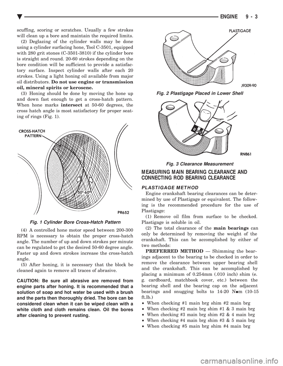
and down fast enough to get a cross-hatch pattern.
When hone marks intersectat 50-60 degrees, the
cross hatch angle is most satisfactory for proper seat-
ing of rings (Fig. 1).
(4) A controlled hone motor speed between 200-300
RPM is necessary to obtain the proper cross-hatch
angle. The number of up and down strokes per minute
can be regulated to get the desired 50-60 degree angle.
Faster up and down strokes increase the cross-hatch
angle. (5) After honing, it is necessary that the block be
cleaned again to remove all traces of abrasive.
CAUTION: Be sure all abrasive are removed from
engine parts after honing. It is recommended that a
solution of soap and hot water be used with a brush
and the parts then thoroughly dried. The bore can be
considered clean when it can be wiped clean with a
white cloth and cloth remains clean. Oil the bores
after cleaning to prevent rusting.
MEASURING MAIN BEARING CLEARANCE AND
CONNECTING ROD BEARING CLEARANCE
PLASTIGAGE METHOD
Engine crankshaft bearing clearances can be deter-
mined by use of Plastigage or equivalent. The follow-
ing is the recommended procedure for the use of
Plastigage: (1) Remove oil film from surface to be checked.
Plastigage is soluble in oil. (2) The total clearance of the main bearingscan
only be determined by removing the weight of the
crankshaft. This can be accomplished by either of
two methods: PREFERRED METHOD Ð Shimming the bear-
ings adjacent to the bearing to be checked in order to
remove the clearance between upper bearing shell
and the crankshaft. This can be accomplished by
placing a minimum of 0.254mm (.010 inch) shim (e.
g. cardboard, matchbook cover, etc.) between the
bearing shell and the bearing cap on the adjacent
bearings and snugging bolts to 14-20 N Im (10-15
ft.lb.)
² When checking #1 main brg shim #2 main brg
²
When checking #2 main brg shim # 1 & 3 main brg
²When checking #3 main brg shim #2 & 4 main brg
²When checking #4 main brg shim #3 & 5 main brg
²When checking #5 main brg shim #4 main brg
Fig. 2 Plastigage Placed in Lower Shell
Fig. 3 Clearance Measurement
Fig. 1 Cylinder Bore Cross-Hatch Pattern
Ä ENGINE 9 - 3
Page 1595 of 2438
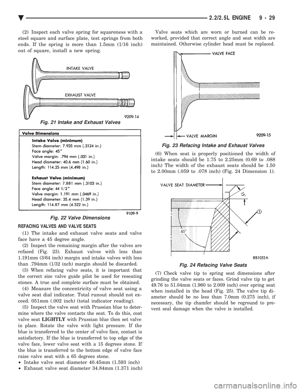
(2) Inspect each valve spring for squareness with a
steel square and surface plate, test springs from both
ends. If the spring is more than 1.5mm (1/16 inch)
out of square, install a new spring.
REFACING VALVES AND VALVE SEATS (1) The intake and exhaust valve seats and valve
face have a 45 degree angle.
(2) Inspect the remaining margin after the valves are
refaced (Fig. 23). Exhaust valves with less than
1.191mm (3/64 inch) margin and intake valves with less
than .794mm (1/32 inch) margin should be discarded. (3) When refacing valve seats, it is important that
the correct size valve guide pilot be used for reseating
stones. A true and complete surface must be obtained.
(4) Measure the concentricity of valve seat using a
valve seat dial indicator. Total runout should not ex-
ceed. 051mm (.002 inch) (total indicator reading).
(5) Inspect the valve seat with Prussian blue to deter-
mine where the valve contacts the seat. To do this, coat
valve seat LIGHTLY with Prussian blue then set valve
in place. Rotate the valve with light pressure. If the
blue is transferred to the center of valve face, contact is
satisfactory. If the blue is transferred to top edge of the
valve face, lower valve seat with a 15 degrees stone. If
the blue is transferred to the bottom edge of valve face
raise valve seat with a 65 degrees stone.
² Intake valve seat diameter 40.45mm (1.593 inch)
² Exhaust valve seat diameter 34.84mm (1.371 inch)
Valve seats which are worn or burned can be re-
worked, provided that correct angle and seat width are
maintained. Otherwise cylinder head must be replaced.
(6) When seat is properly positioned the width of
intake seats should be 1.75 to 2.25mm (0.69 to .088
inch) The width of the exhaust seats should be 1.50
to 2.00mm (.059 to .078 inch) (Fig. 24 Dimension 1).
(7) Check valve tip to spring seat dimensions after
grinding the valve seats or faces. Grind valve tip to get
49.76 to 51.04mm (1.960 to 2.009 inch) over spring seat
when installed in the head (Fig. 25). The valve tip di-
ameter should be no less than 7.0mm (0.275 inch), if
necessary, the tip chamfer should be reground to pre-
vent seal damage when the valve is installed.
Fig. 21 Intake and Exhaust Valves
Fig. 22 Valve Dimensions
Fig. 23 Refacing Intake and Exhaust Valves
Fig. 24 Refacing Valve Seats
Ä 2.2/2.5L ENGINE 9 - 29