1993 CHEVROLET DYNASTY sensor
[x] Cancel search: sensorPage 1874 of 2438
SYSTEM TESTS
WARNING: APPLY PARKING BRAKE AND/OR BLOCK
WHEELS BEFORE PERFORMING ANY TEST ON AN
OPERATING ENGINE.
OBTAINING DIAGNOSTIC TROUBLE CODES
(1) Connect DRBII scan tool to the data link connec-
tor located in the engine compartment near the pow-
ertrain control module (PCM). (2) Start the engine if possible, cycle the transaxle
selector and the A/Cswitch if applicable. Shut off the
engine. (3) Turn the ignition switch on, access Read Fault
Screen. Record all the fault messages shown on the
DRBII scan tool. Observe the malfunction indicator
lamp (Check Engine lamp on the instrument panel).
The lamp should light for 3 seconds then go out (bulb
check). Diagnostic trouble code erasure; access erase
diagnostic trouble code data
STATE DISPLAY TEST MODE
The switch inputs used by the powertrain control
module (PCM) have only two recognized states, HIGH
and LOW. For this reason, the PCM cannot recognize
the difference between a selected switch position ver-
sus an open circuit, a short circuit, or a defective
switch. If the change is displayed, it can be assumed
that the entire switch circuit to the PCM is functional.
From the state display screen access either State
Display Inputs and Outputs or State Display Sensors.
STATE DISPLAY INPUTS AND OUTPUTS
Connect the DRBII scan tool to the vehicle. Access
the State Display screen. Then access Inputs and
Outputs. The following is a list of the engine control
system functions accessible through the Inputs and
Outputs screen. Park/Neutral Switch
Speed Control Resume
Brake Switch
Speed Control On/Off
Speed Control Set
A/C Switch Sense
S/C Vent Solenoid
S/C Vacuum Solenoid
A/C Clutch Relay
EGR Solenoid
Auto Shutdown Relay
Radiator Fan Relay
Purge Solenoid
Torque Converter Clutch Solenoid
Malfunction Indicator Lamp (Check Engine Lamp)
STATE DISPLAY SENSORS
Connect the DRBII scan tool to the vehicle and ac-
cess the State Display screen. Then access Sensor
Display. The following is a list of the engine control
system functions accessible through the Sensor Dis-
play screen. Battery Temperature
Oxygen Sensor Signal
Engine Coolant Temperature
Engine Coolant Temp Sensor
Throttle Position
Minimum Throttle
Battery Voltage
MAP Sensor Reading
Idle Air Control Motor Position
Adaptive Fuel Factor
Barometric Pressure
Min Airflow Idle Speed
Engine Speed
Fault #1 Key-On Info
Module Spark Advance
Speed Control Target
Fault #2 Key-on Info
Fault #3 Key-on Info
Speed Control Status
Speed Control Switch Voltage
Charging System Goal
Theft Alarm Status
Map Sensor Voltage
Vehicle Speed
Oxygen Sensor State
MAP Gauge Reading
Throttle Opening (percentage)
Total Spark Advance
CIRCUIT ACTUATION TEST MODE
The circuit actuation test mode checks for proper
operation of output circuits or devices which the pow-
ertrain control module (PCM) cannot internally rec-
ognize. The PCM can attempt to activate these
outputs and allow an observer to verify proper oper-
ation. Most of the tests provide an audible or visual
indication of device operation (click of relay contacts,
spray fuel, etc.). Except for intermittent conditions, if
a device functions properly during testing, assume
the device, its associated wiring, and driver circuit
working correctly.
OBTAINING CIRCUIT ACTUATION TEST
Connect the DRBII scan tool to the vehicle and ac-
cess the Actuators screen. The following is a list of
the engine control system functions accessible
through Actuators screens. Stop All Tests
Ignition Coil #1
Fuel Injector #1
Fuel Injector #2
Fuel Injector #3
14 - 134 FUEL SYSTEMS Ä
Page 1875 of 2438
Fuel Injector #4
Fuel Injector #5
Fuel Injector #6
Idle Air Control Motor Open/Close
Radiator Fan Relay
A/C Clutch Relay
Auto Shutdown Relay
Purge Solenoid
S/C Serv Solenoids
Generator Field
Tachometer Output
Torque Converter Clutch Solenoid
EGR Solenoid
All Solenoids/Relays
ASD Fuel System Test
Speed Control Vacuum Solenoid
Speed Control Vent Solenoid
THROTTLE BODY MINIMUM AIR FLOW CHECK
PROCEDURE
(1) Warm engine in Park or Neutral until the cool-
ing fan has cycled on and off at least once. (2) Ensure that all accessories are off.
(3) Hook-up the timing check device and tachome-
ter. (4) Disconnect the coolant temperature sensor and
set basic timing to 12É BTDC 62É BTDC.
(5) Shut off engine. Reconnect coolant temperature
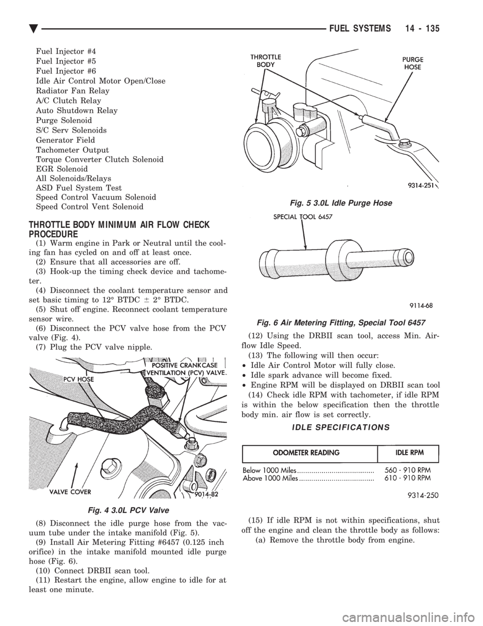
sensor wire. (6) Disconnect the PCV valve hose from the PCV
valve (Fig. 4). (7) Plug the PCV valve nipple.
(8) Disconnect the idle purge hose from the vac-
uum tube under the intake manifold (Fig. 5). (9) Install Air Metering Fitting #6457 (0.125 inch
orifice) in the intake manifold mounted idle purge
hose (Fig. 6). (10) Connect DRBII scan tool.
(11) Restart the engine, allow engine to idle for at
least one minute. (12) Using the DRBII scan tool, access Min. Air-
flow Idle Speed. (13) The following will then occur:
² Idle Air Control Motor will fully close.
² Idle spark advance will become fixed.
² Engine RPM will be displayed on DRBII scan tool
(14) Check idle RPM with tachometer, if idle RPM
is within the below specification then the throttle
body min. air flow is set correctly.
(15) If idle RPM is not within specifications, shut
off the engine and clean the throttle body as follows: (a) Remove the throttle body from engine.
Fig. 4 3.0L PCV Valve
Fig. 5 3.0L Idle Purge Hose
Fig. 6 Air Metering Fitting, Special Tool 6457
IDLE SPECIFICATIONS
Ä FUEL SYSTEMS 14 - 135
Page 1878 of 2438
3.0L MULTI-PORT FUEL INJECTIONÐSERVICE PROCEDURES INDEX
page page
Idle Air Control Motor .................... 138
Canister Purge Solenoid Service ............ 143
Fuel Injector Rail Assembly ................ 139
Fuel Injectors .......................... 142
Fuel Pressure Regulator Service ............ 141
Fuel System Pressure Release Procedure ..... 138 Heated Oxygen Sensor (O
2Sensor)
......... 144
Manifold Absolute Pressure (MAP) Sensor ..... 143
PCM ................................. 143
Throttle Body ........................... 138
Throttle Body Service .................... 138
Throttle Position Sensor .................. 138
THROTTLE BODY SERVICE
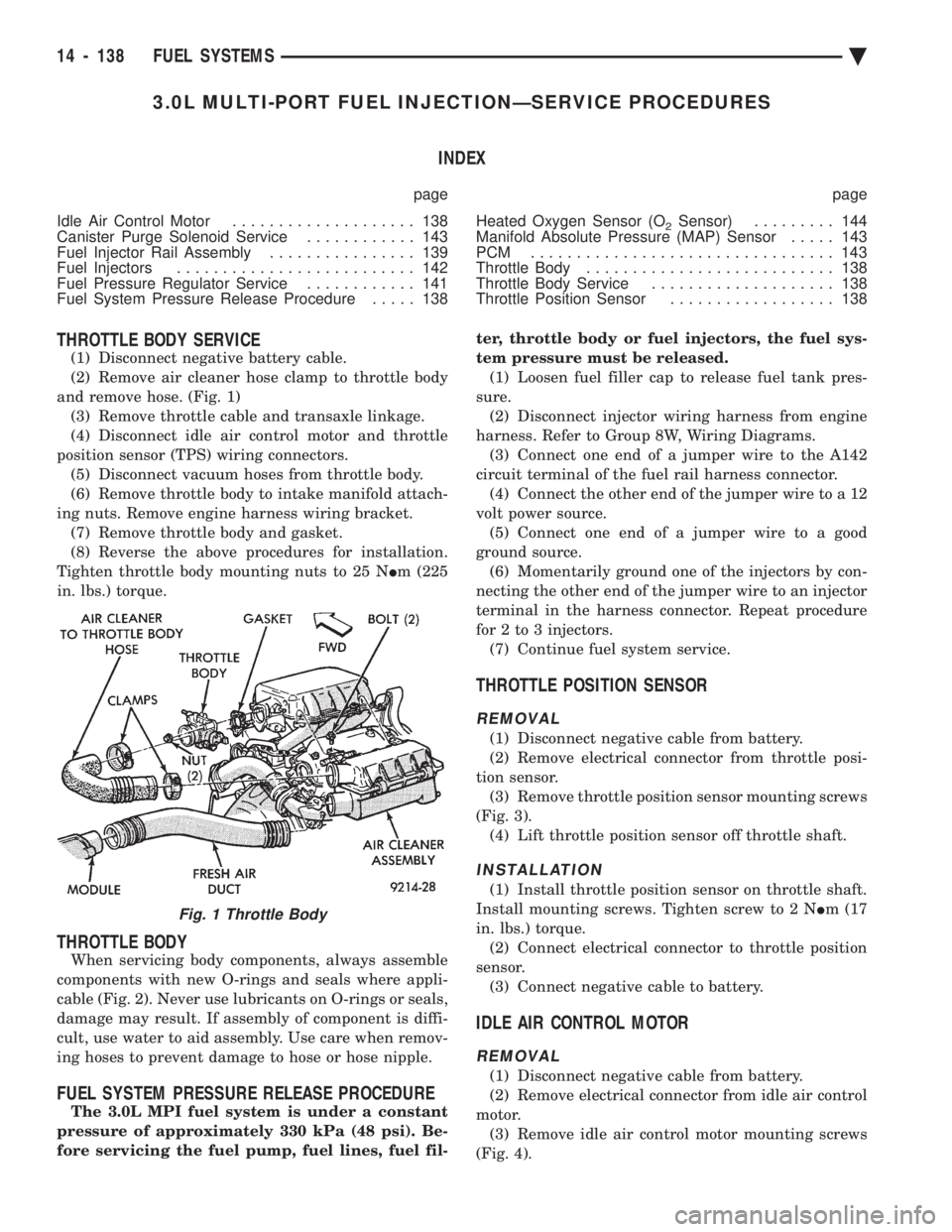
(1) Disconnect negative battery cable.
(2) Remove air cleaner hose clamp to throttle body
and remove hose. (Fig. 1) (3) Remove throttle cable and transaxle linkage.
(4) Disconnect idle air control motor and throttle
position sensor (TPS) wiring connectors. (5) Disconnect vacuum hoses from throttle body.
(6) Remove throttle body to intake manifold attach-
ing nuts. Remove engine harness wiring bracket. (7) Remove throttle body and gasket.
(8) Reverse the above procedures for installation.
Tighten throttle body mounting nuts to 25 N Im (225
in. lbs.) torque.
THROTTLE BODY
When servicing body components, always assemble
components with new O-rings and seals where appli-
cable (Fig. 2). Never use lubricants on O-rings or seals,
damage may result. If assembly of component is diffi-
cult, use water to aid assembly. Use care when remov-
ing hoses to prevent damage to hose or hose nipple.
FUEL SYSTEM PRESSURE RELEASE PROCEDURE
The 3.0L MPI fuel system is under a constant
pressure of approximately 330 kPa (48 psi). Be-
fore servicing the fuel pump, fuel lines, fuel fil- ter, throttle body or fuel injectors, the fuel sys-
tem pressure must be released. (1) Loosen fuel filler cap to release fuel tank pres-
sure. (2) Disconnect injector wiring harness from engine
harness. Refer to Group 8W, Wiring Diagrams. (3) Connect one end of a jumper wire to the A142
circuit terminal of the fuel rail harness connector. (4) Connect the other end of the jumper wire to a 12
volt power source. (5) Connect one end of a jumper wire to a good
ground source. (6) Momentarily ground one of the injectors by con-
necting the other end of the jumper wire to an injector
terminal in the harness connector. Repeat procedure
for 2 to 3 injectors. (7) Continue fuel system service.
THROTTLE POSITION SENSOR
REMOVAL
(1) Disconnect negative cable from battery.
(2) Remove electrical connector from throttle posi-
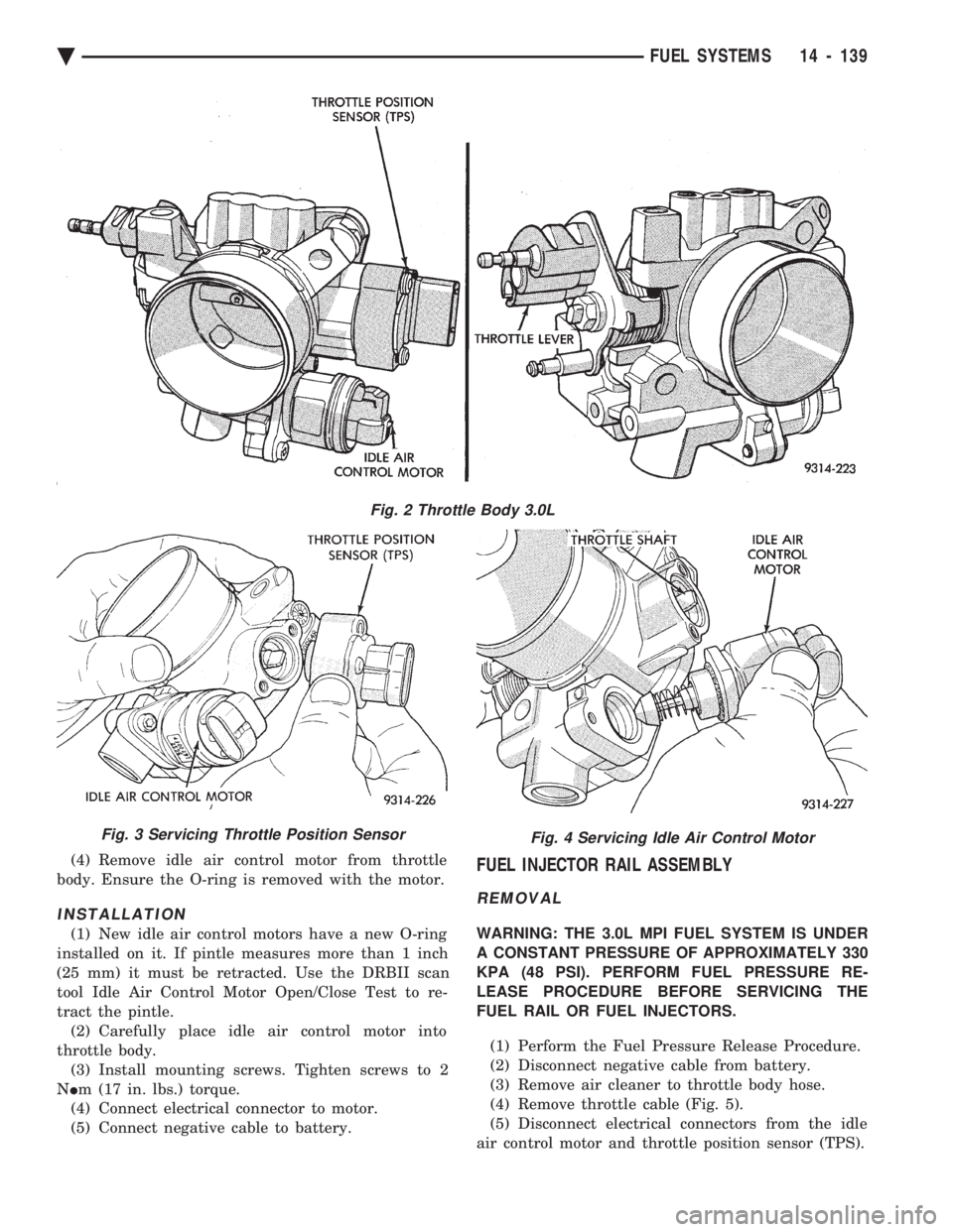
tion sensor. (3) Remove throttle position sensor mounting screws
(Fig. 3). (4) Lift throttle position sensor off throttle shaft.
INSTALLATION
(1) Install throttle position sensor on throttle shaft.
Install mounting screws. Tighten screw to 2 N Im (17
in. lbs.) torque. (2) Connect electrical connector to throttle position
sensor. (3) Connect negative cable to battery.
IDLE AIR CONTROL MOTOR
REMOVAL
(1) Disconnect negative cable from battery.
(2) Remove electrical connector from idle air control
motor. (3) Remove idle air control motor mounting screws
(Fig. 4).
Fig. 1 Throttle Body
14 - 138 FUEL SYSTEMS Ä
Page 1879 of 2438
(4) Remove idle air control motor from throttle
body. Ensure the O-ring is removed with the motor.
INSTALLATION
(1) New idle air control motors have a new O-ring
installed on it. If pintle measures more than 1 inch
(25 mm) it must be retracted. Use the DRBII scan
tool Idle Air Control Motor Open/Close Test to re-
tract the pintle. (2) Carefully place idle air control motor into
throttle body. (3) Install mounting screws. Tighten screws to 2
N Im (17 in. lbs.) torque.
(4) Connect electrical connector to motor.
(5) Connect negative cable to battery.
FUEL INJECTOR RAIL ASSEMBLY
REMOVAL
WARNING: THE 3.0L MPI FUEL SYSTEM IS UNDER
A CONSTANT PRESSURE OF APPROXIMATELY 330
KPA (48 PSI). PERFORM FUEL PRESSURE RE-
LEASE PROCEDURE BEFORE SERVICING THE
FUEL RAIL OR FUEL INJECTORS.
(1) Perform the Fuel Pressure Release Procedure.
(2) Disconnect negative cable from battery.
(3) Remove air cleaner to throttle body hose.
(4) Remove throttle cable (Fig. 5).
(5) Disconnect electrical connectors from the idle
air control motor and throttle position sensor (TPS).
Fig. 2 Throttle Body 3.0L
Fig. 3 Servicing Throttle Position SensorFig. 4 Servicing Idle Air Control Motor
Ä FUEL SYSTEMS 14 - 139
Page 1880 of 2438
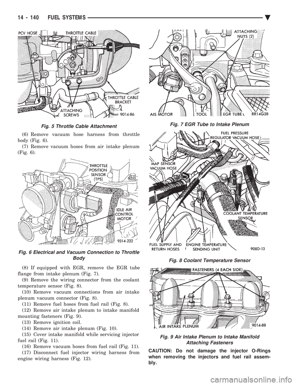
(6) Remove vacuum hose harness from throttle
body (Fig. 6). (7) Remove vacuum hoses from air intake plenum
(Fig. 6).
(8) If equipped with EGR, remove the EGR tube
flange from intake plenum (Fig. 7). (9) Remove the wiring connector from the coolant
temperature sensor (Fig. 8). (10) Remove vacuum connections from air intake
plenum vacuum connector (Fig. 8). (11) Remove fuel hoses from fuel rail (Fig. 8).
(12) Remove air intake plenum to intake manifold
mounting fasteners (Fig. 9). (13) Remove ignition coil.
(14) Remove air intake plenum (Fig. 10).
(15) Cover intake manifold while servicing injector
fuel rail (Fig. 11). (16) Remove vacuum hoses from fuel rail (Fig. 11).
(17) Disconnect fuel injector wiring harness from
engine wiring harness (Fig. 12). CAUTION: Do not damage the injector O-Rings
when removing the injectors and fuel rail assem-
bly.
Fig. 5 Throttle Cable Attachment
Fig. 6 Electrical and Vacuum Connection to Throttle Body
Fig. 7 EGR Tube to Intake Plenum
Fig. 8 Coolant Temperature Sensor
Fig. 9 Air Intake Plenum to Intake ManifoldAttaching Fasteners
14 - 140 FUEL SYSTEMS Ä
Page 1881 of 2438
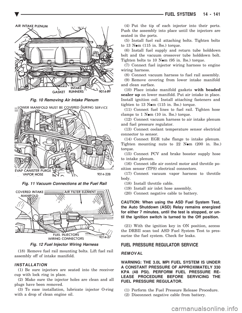
(18) Remove fuel rail mounting bolts. Lift fuel rail
assembly off of intake manifold.
INSTALLATION
(1) Be sure injectors are seated into the receiver
cup with lock ring in place. (2) Make sure the injector holes are clean and all
plugs have been removed. (3) To ease installation, lubricate injector O-ring
with a drop of clean engine oil. (4) Put the tip of each injector into their ports.
Push the assembly into place until the injectors are
seated in the ports. (5) Install fuel rail attaching bolts. Tighten bolts
to 13 N Im (115 in. lbs.) torque.
(6) Install fuel supply and return tube holddown
bolt and the vacuum crossover tube holddown bolt.
Tighten bolts to 10 N Im (95 in. lbs.) torque.
(7) Connect fuel injector wiring harness to engine
wiring harness. (8) Connect vacuum harness to fuel rail assembly.
(9) Remove covering from lower intake manifold
and clean surface. (10) Place intake manifold gaskets with beaded
sealer up on lower manifold. Put air intake in place.
Install ignition coil. Install attaching fasteners and
tighten to 13 N Im (115 in. lbs.) torque.
(11) Connect fuel lines to fuel rail. Tighten hose
clamps to 1 N Im (10 in. lbs.) torque.
(12) Connect vacuum harness to air intake plenum
and fuel pressure regulator. (13) Connect coolant temperature sensor electrical
connector to sensor. (14) Connect EGR tube flange to intake plenum.
Tighten mounting nuts to 22 N Im (200 in. lbs.)
torque. (15) Connect PCV and brake booster supply hose
to intake plenum. (16) Connect idle air control motor and throttle po-
sition sensor (TPS) electrical connectors. (17) Connect vacuum vapor harness to throttle
body. (18) Install throttle cable.
(19) Install air inlet hose assembly.
(20) Connect negative cable to battery.
CAUTION: When using the ASD Fuel System Test,
the Auto Shutdown (ASD) Relay remains energized
for either 7 minutes, until the test is stopped, or un-
til the ignition switch is turned to the Off position. (21) With the ignition key in ON position, access
the DRBII scan tool ASD Fuel System Test to pres-
surize the fuel system. Check for leaks.
FUEL PRESSURE REGULATOR SERVICE
REMOVAL
WARNING: THE 3.0L MPI FUEL SYSTEM IS UNDER
A CONSTANT PRESSURE OF APPROXIMATELY 330
KPA (48 PSI). PERFORM FUEL PRESSURE RE-
LEASE PROCEDURE BEFORE SERVICING THE
FUEL PRESSURE REGULATOR.
(1) Perform the Fuel Pressure Release Procedure.
(2) Disconnect negative cable from battery.
Fig. 10 Removing Air Intake Plenum
Fig. 11 Vacuum Connections at the Fuel Rail
Fig. 12 Fuel Injector Wiring Harness
Ä FUEL SYSTEMS 14 - 141
Page 1883 of 2438
(7) Check injector O-ring for damage. If O-ring is
damaged, it must be replaced. If injector is to be re-
used, a protective cap must be installed on the injec-
tor tip to prevent damage. (8) Repeat procedure for remaining injectors.
INSTALLATION
(1) Before installing an injector, the rubber O-ring
must be lubricated with a drop of clean engine oil to
aid in installation. (2) Being careful not to damage O-ring, install in-
jector nozzle end into fuel rail receiver cap (Fig. 15). (3) Install injector clip by sliding open end into top
slot of the injector. The edge of the receiver cup will
slide into the side slots of clip (Fig. 14). (4) Repeat steps for remaining injectors.
(5) Install fuel rail assembly. Refer to Fuel Rail
Assembly Installation in this section. (6) Connect electrical connectors to injectors in cor-
rect order. (7) Connect negative battery cable.
CAUTION: When using the ASD Fuel System Test,
the Auto Shutdown (ASD) Relay remains energized
for either 7 minutes, until the test is stopped, or un-
til the ignition switch is turned to the Off position.
(8) With the ignition key in ON position, access
the DRBII scan tool ASD Fuel System Test to pres-
surize the fuel system. Check for leaks.
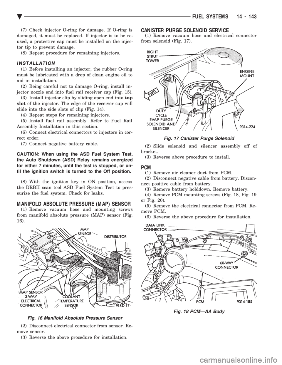
MANIFOLD ABSOLUTE PRESSURE (MAP) SENSOR
(1) Remove vacuum hose and mounting screws
from manifold absolute pressure (MAP) sensor (Fig.
16).
(2) Disconnect electrical connector from sensor. Re-
move sensor. (3) Reverse the above procedure for installation.
CANISTER PURGE SOLENOID SERVICE
(1) Remove vacuum hose and electrical connector
from solenoid (Fig. 17).
(2) Slide solenoid and silencer assembly off of
bracket. (3) Reverse above procedure to install.
PCM
(1) Remove air cleaner duct from PCM.
(2) Disconnect negative cable from battery. Discon-
nect positive cable from battery. (3) Remove battery holddown. Remove battery.
(4) Remove PCM mounting screws (Fig. 18, Fig. 19
or Fig. 20). (5) Remove the electrical connector from PCM. Re-
move PCM. (6) Reverse the above procedure for installation.
Fig. 16 Manifold Absolute Pressure Sensor
Fig. 17 Canister Purge Solenoid
Fig. 18 PCMÐAA Body
Ä FUEL SYSTEMS 14 - 143
Page 1884 of 2438
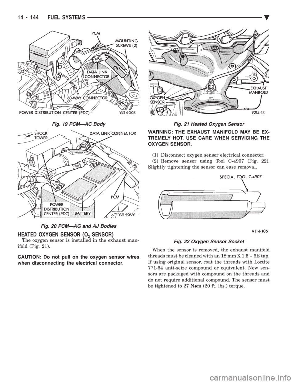
HEATED OXYGEN SENSOR (O2SENSOR)
The oxygen sensor is installed in the exhaust man-
ifold (Fig. 21).
CAUTION: Do not pull on the oxygen sensor wires
when disconnecting the electrical connector. WARNING: THE EXHAUST MANIFOLD MAY BE EX-
TREMELY HOT. USE CARE WHEN SERVICING THE
OXYGEN SENSOR.
(1) Disconnect oxygen sensor electrical connector.
(2) Remove sensor using Tool C-4907 (Fig. 22).
Slightly tightening the sensor can ease removal.
When the sensor is removed, the exhaust manifold
threads must be cleaned with an 18 mm X 1.5 + 6E tap.
If using original sensor, coat the threads with Loctite
771-64 anti-seize compound or equivalent. New sen-
sors are packaged with compound on the threads and
do not require additional compound. The sensor must
be tightened to 27 N Im (20 ft. lbs.) torque.
Fig. 19 PCMÐAC Body
Fig. 20 PCMÐAG and AJ Bodies
Fig. 21 Heated Oxygen Sensor
Fig. 22 Oxygen Sensor Socket
14 - 144 FUEL SYSTEMS Ä