1993 CHEVROLET DYNASTY sensor
[x] Cancel search: sensorPage 1916 of 2438
(5) Reverse the above procedure for installation.
CRANKSHAFT POSITION SENSOR
REMOVAL
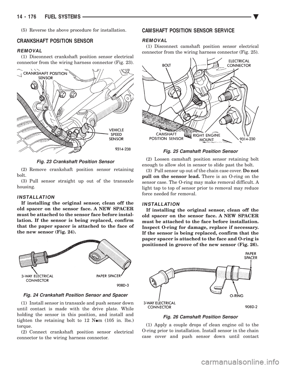
(1) Disconnect crankshaft position sensor electrical
connector from the wiring harness connector (Fig. 23).
(2) Remove crankshaft position sensor retaining
bolt. (3) Pull sensor straight up out of the transaxle
housing.
INSTALLATION
If installing the original sensor, clean off the
old spacer on the sensor face. A NEW SPACER
must be attached to the sensor face before instal-
lation. If the sensor is being replaced, confirm
that the paper spacer is attached to the face of
the new sensor (Fig. 24).
(1) Install sensor in transaxle and push sensor down
until contact is made with the drive plate. While
holding the sensor in this position, and install and
tighten the retaining bolt to 12 N Im (105 in. lbs.)
torque. (2) Connect crankshaft position sensor electrical
connector to the wiring harness connector.
CAMSHAFT POSITION SENSOR SERVICE
REMOVAL
(1) Disconnect camshaft position sensor electrical
connector from the wiring harness connector (Fig. 25).
(2) Loosen camshaft position sensor retaining bolt
enough to allow slot in sensor to slide past the bolt. (3) Pull sensor up out of the chain case cover. Do not
pull on the sensor lead. There is an O-ring on the
sensor case. The O-ring may make removal difficult. A
light tap to top of sensor prior to removal may reduce
force needed for removal.
INSTALLATION
If installing the original sensor, clean off the
old spacer on the sensor face. A NEW SPACER
must be attached to the face before installation.
Inspect O-ring for damage, replace if necessary.
If the sensor is being replaced, confirm that the
paper spacer is attached to the face and O-ring is
positioned in groove of the new sensor (Fig. 26).
(1) Apply a couple drops of clean engine oil to the
O-ring prior to installation. Install sensor in the chain
case cover and push sensor down until contact
Fig. 23 Crankshaft Position Sensor
Fig. 24 Crankshaft Position Sensor and Spacer
Fig. 25 Camshaft Position Sensor
Fig. 26 Camshaft Position Sensor
14 - 176 FUEL SYSTEMS Ä
Page 1917 of 2438
is made with the camshaft gear. While holding the
sensor in this position, install and tighten the retain-
ing bolt 12 N Im (105 in. lbs.) torque.
(2) Connect camshaft position sensor electrical con-
nector to harness connector. Position connector away
from the accessory belt.
HEATED OXYGEN SENSOR (O2SENSOR) SERVICE
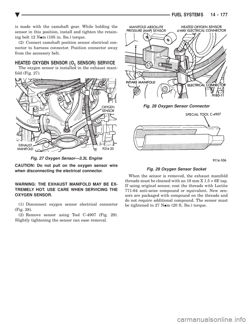
The oxygen sensor is installed in the exhaust mani-
fold (Fig. 27).
CAUTION: Do not pull on the oxygen sensor wire
when disconnecting the electrical connector.
WARNING: THE EXHAUST MANIFOLD MAY BE EX-
TREMELY HOT. USE CARE WHEN SERVICING THE
OXYGEN SENSOR.
(1) Disconnect oxygen sensor electrical connector
(Fig. 28). (2) Remove sensor using Tool C-4907 (Fig. 29).
Slightly tightening the sensor can ease removal. When the sensor is removed, the exhaust manifold
threads must be cleaned with an 18 mm X 1.5 + 6E tap.
If using original sensor, coat the threads with Loctite
771-64 anti-seize compound or equivalent. New sen-
sors are packaged with compound on the threads and
do not require additional compound. The sensor must
be tightened to 27 N Im (20 ft. lbs.) torque.
Fig. 27 Oxygen SensorÐ3.3L Engine
Fig. 28 Oxygen Sensor Connector
Fig. 29 Oxygen Sensor Socket
Ä FUEL SYSTEMS 14 - 177
Page 1995 of 2438
THREE SPEED TORQUEFLITE AUTOMATIC TRANSAXLE INDEX
page page
Accumulator-Recondition ................... 67
Aluminum Thread Repair ................... 48
Assembly Subassembly Installation ........... 57
Band Adjustment ......................... 47
Bearing Adjustment Procedures .............. 81
Clutch and Servo Air Pressure Tests .......... 43
Differential Repair ........................ 76
Disassembly Subassembly Removal .......... 50
Fluid and Filter Change .................... 40
Fluid Drain and Refill ..................... 40
Fluid Leakage-Transaxle Torque Converter Housing Area .......................... 44
Fluid Level and Condition .................. 40
Front Clutch-Recondition ................... 62
Front Planetary & Annulus Gear-Recondition .... 65
Gearshift Linkage Adjustment ............... 46
General Information ....................... 35
Governor ............................... 48
Hydraulic Control Pressure Adjustments ....... 47
Hydraulic Pressure Tests ................... 42
Kickdown Servo (Controlled Load)-Recondition . . 67 Low/Reverse Servo-Recondition
.............. 66
Oil Cooler Flow Check .................... 48
Oil Coolers and Tubes Reverse Flushing ...... 48
Oil Pump-Recondition ..................... 62
Output Shaft Repair ...................... 71
Park/Neutral Position and Back-Up Lamp Switch . 47
Parking Pawl ............................ 71
Pump Oil Seal-Replacement ................ 61
Rear Clutch-Recondition ................... 64
Road Test .............................. 40
Selection of Lubricant ..................... 40
Special Additives ......................... 40
Three Speed Torqueflite General Diagnosis ..... 36
Throttle Pressure Linkage Adjustment ......... 46
Torque Converter Clutch Solenoid Wiring Connector ............................ 40
Transaxle and Torque Converter Removal ...... 48
Transfer Shaft Repair ..................... 68
Valve Body-Recondition .................... 57
Vehicle Speed Sensor Pinion Gear ........... 47
GENERAL INFORMATION
Safety goggles should be worn at all times
when working on these transaxles. This transaxle combines a fully automatic 3 speed
transmission, final drive gearing, and differential into
a front wheel drive system. The unit is a Metric
design. The identification markings and usage of the
transaxle are charted in Diagnosis and Tests. Transaxle operation requirements are differ-
ent for each vehicle and engine combination and
some internal parts will be different to provide
for this. Therefore, when replacing parts, refer to
the seven digit part number stamped on rear of
the transaxle oil pan flange. Within this transaxle, there are 3 primary areas:
(1) Main center line plus valve body.
(2) Transfer shaft center line (includes governor and
parking sprag). (3) Differential center line. Center distances be-
tween the main rotating parts in these 3 areas are held
precise. This maintains a low noise level through
smooth accurate mesh of the gears. The torque converter, transaxle area, and differential
are housed in an integral aluminum die casting. The
differential oil sump is common with thetransaxle
sump. Separate filling of the differential is NOT nec-
essary. The torque converter is attached to the crankshaft
through a flexible driving plate. Cooling of the con-
verter is accomplished by circulating the transaxle
fluid through an oil-to-water type cooler located in the
radiator side tank and/or an oil-to air heat ex- changer. The torque converter assembly is a sealed
unit that cannot be disassembled.
The transaxle fluid is filtered by an internal filter
attached to the lower side of the valve body assem-
bly. Engine torque is transmitted to the torque con-
verter then, through the input shaft to multiple-disc
clutches in the transaxle. The power flow depends on
the application of the clutches and bands. Refer to
Elements in Use Chart in Diagnosis and Tests sec-
tion. The transaxle consists of two multiple-disc
clutches, an overrunning clutch, two servos, a hy-
draulic accumulator, two bands, and two planetary
gear sets. They provide three forward ratios and a re-
verse ratio. The common sun gear of the planetary
gear sets is connected to the front clutch by a driving
shell. The drive shell is splined to the sun gear and
to the front clutch retainer. The hydraulic system
consists of an oil pump, and a single valve body
which contains all of the valves except the governor
valves. The transaxle sump and differential sump are
both vented through the dipstick.Output torque
from the main center line is delivered through heli-
cal gears to the transfer shaft.This gear set is a
factor of the final drive (axle) ratio. The shaft also
carries the governor and parking sprag. An integral
helical gear on the transfer shaft drives the differen-
tial ring gear. The final drive gearing is completed
with one of three gear sets producing overall top gear
ratios of 2.78, 3.02, or 3.22 depending on model and
application.
Ä TRANSAXLE 21 - 35
Page 2007 of 2438
BAND ADJUSTMENT
KICKDOWN BAND (FRONT)
The kickdown band adjusting screw is located on
left side (top front) of the transaxle case. (1) Loosen locknut and back off nut approximately
five turns. Test adjusting screw for free turning in
the transaxle case. (2) Using wrench, Tool C-3880-A with adapter Tool
C-3705, tighten band adjusting screw to 5 N Im (47 to
50 in. lbs.). If adapter C-3705 is not used, tighten ad-
justing screw to 8 N Im (72 in. lbs.) which is the true
torque. (3) Back off adjusting screw the number of turns
listed in Specifications . Hold adjusting screw in this
position and tighten locknut to 47 N Im (35 ft. lbs.)
LOW/REVERSE BAND-REAR
To adjust low-reverse band, proceed as follows:
(1) Loosen and back off locknut approximately 5
turns. (2) Using an inch-pound torque wrench, tighten
adjusting screw to 5 N Im (41 in. lbs.) true torque.
(3) Back off adjusting screw the number of turns
listed under Specifications in the rear of the Tran-
saxle Section in this service manual. (4) Tighten locknut to 14 N Im (10 ft. lbs.).
HYDRAULIC CONTROL PRESSURE ADJUSTMENTS
LINE PRESSURE
An incorrect throttle pressure setting will cause in-
correct line pressure readings even though line pres-
sure adjustment is correct. Always inspect and
correct throttle pressure adjustment before adjusting
the line pressure. The approximate adjustment for line pressure is
1-5/16 inches, measured from valve body to inner
edge of adjusting nut. However, due to manufactur-
ing tolerances, the adjustment can be varied to ob-
tain specified line pressure. The adjusting screw may be turned with an Allen
wrench. One complete turn of adjusting screw
changes closed throttle line pressure approximately
1-2/3 psi. Turning adjusting screw counterclockwise
increases pressure, and clockwise decreases pressure.
THROTTLE PRESSURE
Throttle pressures cannot be tested accurately;
therefore, the adjustment should be measured if a
malfunction is evident. (1) Insert gauge pin of Tool C-3763 between the
throttle lever cam and kickdown valve. (2) By pushing in on tool, compress kickdown
valve against its spring so throttle valve is com-
pletely bottomed inside the valve body. (3) While compressing spring, turn throttle lever
stop screw with adapter C-4553. Turn until head of screw touches throttle lever tang, with throttle lever
cam touching tool and throttle valve bottomed. Be sure
adjustment is made with spring fully compressed and
valve bottomed in the valve body.
VEHICLE SPEED SENSOR PINION GEAR
When the speed sensor is removed for any reason, a
NEW O-ring must be installed on its outside diameter.
REMOVAL AND INSTALLATION
(1) Remove speedometer cable (if so equipped).
(2) Remove harness connector from sensor. Make
sure weatherseal stays on harness connector. (3) Remove bolt securing the distance sensor in the
extension housing. (4) Carefully pull sensor and pinion gear assembly
out of extension housing. (5) Remove pinion gear from sensor.
(6) To install, reverse the above procedure. Make
sure extension housing and sensor flange are clean
prior to installation. Always use a NEW sensor O-ring. (7) Tighten securing bolt to 7 N Im (60 in. lbs.).
Tighten speedometer cable to 4 N Im (35 in. lbs.).
PARK/NEUTRAL POSITION AND BACK-UP LAMP
SWITCH
REPLACEMENT AND TEST
The Park/Neutral switch is the center terminal of the
3 terminal switch. It provides ground for the starter
solenoid circuit through the selector lever in only Park
and Neutral positions. (1) To test switch, remove wiring connector from
switch and test for continuity between center pin of
switch and transaxle case. Continuity should exist only
when transaxle is in Park or Neutral. (2) Check gearshift cable adjustment before replac-
ing a switch which tests bad. (3) Unscrew switch from transaxle case allowing
fluid to drain into a container. Move selector lever to
Park and then to Neutral positions. Inspect to see that
the switch operating lever fingers are centered in
switch opening in the case. (4) Screw the switch with a new seal into transaxle
case and tighten to 33 N Im (24 ft. lbs.). Retest switch
with the test lamp. (5) Add fluid to transaxle to bring up to proper level.
(6) The back-up lamp switch circuit is through the
two outside terminals of the 3 terminal switch. (7) To test switch, remove wiring connector from
switch and test for continuity between the two outside
pins. (8) Continuity should exist only with transaxle in
Reverse position. (9) No continuity should exist from either pin to the
case.
Ä TRANSAXLE 21 - 47
Page 2045 of 2438
41TE FOUR SPEED AUTOMATIC TRANSAXLE INDEX
page page
41TE Transaxle General Diagnosis ........... 88
Aluminum Thread Repair ................... 98
Bearing Adjustment Procedure .............. 141
Clutch Air Pressure Tests .................. 95
Coolers and Tubes Reverse Flushing ......... 98
Diagnosis Chart ``B'' ....................... 90
Diagnosis Trouble Code Chart ``A'' ............ 89
Differential Repair ....................... 136
Fluid and Filter Changes ................... 93
Fluid Drain and Refill ..................... 93
Fluid Leakage-Torque Converter Housing Area . . 97
Fluid Level and Condition .................. 93
Gearshift Linkage Adjustment ............... 98
General Information ....................... 85
Hydraulic Pressure Tests ................... 94
Input Clutches-Recondition ................ 121
Oil Cooler Flow Check .................... 99 Oil Pump Seal Replace
................... 136
Park/Neutral Position Switch ............... 102
Pinion Factor Procedure .................. 104
Road Test .............................. 93
Selection of Lubricant ..................... 93
Solenoid Assembly-Replace ................ 101
Special Additives ......................... 93
Speed Sensor-Input ...................... 102
Speed Sensor-Output .................... 103
Torque Converter Clutch Break-In Procedure . . . 104
Transaxle Quick Learn Procedure ........... 103
Transaxle Recondition .................... 105
Transaxle Removal and Installation ........... 99
Transmission Control Module ............... 103
Transmission Range Switch ................ 102
Valve Body-Recondition ................... 132
GENERAL INFORMATION
The 41TE four-speed FWD transaxle uses fully-
adaptive controls. Adaptive controls are those which
perform their functions based on real-time feedback
sensor information. The transaxle uses hydraulically
applied clutches to shift a planetary gear train.
TRANSAXLE IDENTIFICATION
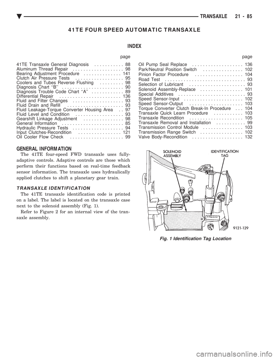
The 41TE transaxle identification code is printed
on a label. The label is located on the transaxle case
next to the solenoid assembly (Fig. 1). Refer to Figure 2 for an internal view of the tran-
saxle assembly.
Fig. 1 Identification Tag Location
Ä TRANSAXLE 21 - 85
Page 2047 of 2438
OPERATION
The 41TE transaxle provides forward ratios of 2.84,
1.57, 1.00, and 0.69 with torque converter clutch
available in 2nd, direct, or overdrive gear; the Re-
verse ratio is 2.21. The shift lever is conventional
with six positions: P, R, N, OD, 3, and L. When OD
is selected the transaxle shifts normally through all
four speeds with torque converter clutch available in
overdrive; this position is recommended for most
driving. The 3 position is tailored for use in hilly or
mountainous driving. When 3 is selected, the trans-
mission uses only 1st, 2nd, and direct gears with
2nd-direct shift delayed to 40 mph or greater. When
operating in 3 or L positions torque converter clutch
application occurs in direct gear for improved trans-
mission cooling under heavy loads. If high engine
coolant temperature occurs, the torque converter
clutch will also engage in 2nd gear. The L position
provides maximum engine braking for descending
steep grades. Unlike most current transaxles, up-
shifts are provided to 2nd or direct gear at peak en-
gine speeds if the accelerator is depressed. This
provides engine over-speed protection and maximum
performance.
CLUTCH AND GEAR
The transaxle consists of:
² Three multiple disc input clutches
² Two multiple disc grounded clutches
² Four hydraulic accumulators
² Two planetary gear sets
This provides four forward ratios and a reverse ra-
tio. The clutch-apply pistons were designed with cen-
trifugally balanced oil cavities so that quick response
and good control can be achieved at any speed. A
push/pull piston is incorporated for two of the three
input clutches.
CAUTION: Some clutch packs appear similar, but
they are not the same. Do not interchange clutch
components as they might fail.
HYDRAULICS
The hydraulics of the transaxle provide the manual
shift lever select function, main line pressure regula-
tion, and torque converter and cooler flow control.
Oil flow to the friction elements is controlled directly
by four solenoid valves. The hydraulics also include a
unique logic-controlled ``solenoid torque converter
clutch control valve''. This valve locks out the 1st
gear reaction element with the application of 2nd, di-
rect, or overdrive gear elements. It also redirects the
1st gear solenoid output so that it can control torque
converter clutch operation. To regain access to 1st
gear, a special sequence of solenoid commands must
be used to unlock and move the solenoid torque con-
verter clutch control valve. This precludes any appli- cation of the 1st gear reaction element with other
elements applied. It also allows one solenoid to con-
trol two friction elements.
Small, high-rate accumulators are provided in each
controlled friction element circuit. These serve to ab-
sorb the pressure responses, and allow the controls to
read and respond to changes that are occurring.
SOLENOIDS
Since the solenoid valves perform virtually all con-
trol functions, these valves must be extremely dura-
ble and tolerant of normal dirt particles. For that
reason hardened-steel poppet and ball valves are
used. These are free from any close operating clear-
ances, and the solenoids operate the valves directly
without any intermediate element. Direct operation
means that these units must have very high output
so that they can close against the sizeable flow areas
and high line pressures. Fast response is also re-
quired to meet the control requirements. Two of the solenoids are normally-venting and two
are normally-applying; this was done to provide a de-
fault mode of operation. With no electrical power, the
transmission provides 2nd gear in OD, 3,orLshift
lever positions. All other transmission lever positions
will operate normally. The choice of 2nd gear was
made to provide adequate breakaway performance
while still accommodating highway speeds.
SENSORS
There are three pressure switches to identify sole-
noid application and two speed sensors to read input
(torque converter turbine) and output (parking sprag)
speeds. There is also a position switch to indicate the
manual shift lever position. The pressure switches
are incorporated in an assembly with the solenoids.
Engine speed, throttle position, temperature, etc., are
also observed. Some of these signals are read directly
from the engine control sensors; others are read from
a multiplex circuit with the powertrain control mod-
ule.
ELECTRONICS
The 41TE transmission control module is located
underhood in a potted, die-cast aluminum housing
with a sealed, 60-way connector.
ELECTRONIC MODULATED CONVERTER CLUTCH (EMCC)
The EMCC enables the torque converter clutch to
partially engage between 23 to 47 MPH before full
engagement at about 50 MPH and beyond. This fea-
ture is on all vehicles equipped with the 41TE tran-
saxle.
ADAPTIVE CONTROLS
These controls function by reading the input and
output speeds over 140 times a second and respond-
Ä TRANSAXLE 21 - 87
Page 2060 of 2438
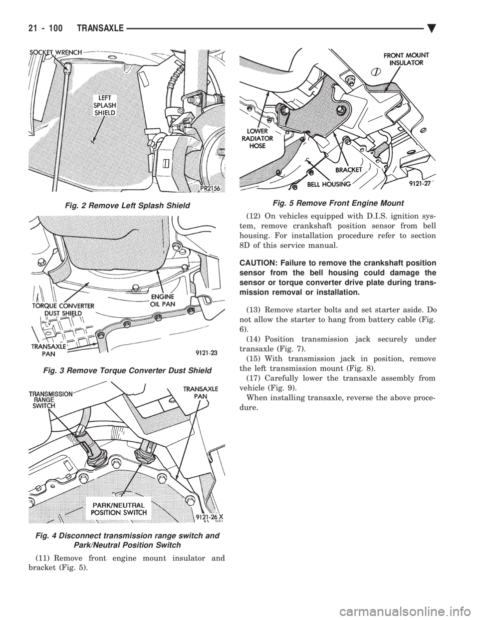
(11) Remove front engine mount insulator and
bracket (Fig. 5). (12) On vehicles equipped with D.I.S. ignition sys-
tem, remove crankshaft position sensor from bell
housing. For installation procedure refer to section
8D of this service manual.
CAUTION: Failure to remove the crankshaft position
sensor from the bell housing could damage the
sensor or torque converter drive plate during trans-
mission removal or installation.
(13) Remove starter bolts and set starter aside. Do
not allow the starter to hang from battery cable (Fig.
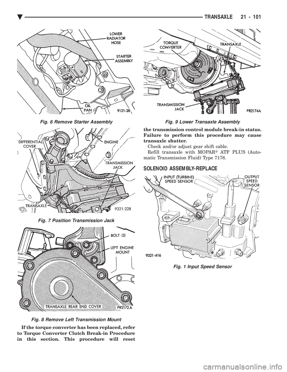
6). (14) Position transmission jack securely under
transaxle (Fig. 7). (15) With transmission jack in position, remove
the left transmission mount (Fig. 8). (17) Carefully lower the transaxle assembly from
vehicle (Fig. 9). When installing transaxle, reverse the above proce-
dure.
Fig. 2 Remove Left Splash Shield
Fig. 3 Remove Torque Converter Dust Shield
Fig. 4 Disconnect transmission range switch and Park/Neutral Position Switch
Fig. 5 Remove Front Engine Mount
21 - 100 TRANSAXLE Ä
Page 2061 of 2438
If the torque converter has been replaced, refer
to Torque Converter Clutch Break-in Procedure
in this section. This procedure will reset the transmission control module break-in status.
Failure to perform this procedure may cause
transaxle shutter. Check and/or adjust gear shift cable.
Refill transaxle with MOPAR tATF PLUS (Auto-
matic Transmission Fluid) Type 7176.
SOLENOID ASSEMBLY-REPLACE
Fig. 9 Lower Transaxle Assembly
Fig. 1 Input Speed Sensor
Fig. 6 Remove Starter Assembly
Fig. 7 Position Transmission Jack
Fig. 8 Remove Left Transmission Mount
Ä TRANSAXLE 21 - 101