1993 CHEVROLET DYNASTY brakes
[x] Cancel search: brakesPage 74 of 2438
the lower clamps and bolts. The center offset in the
sway bar should be oriented toward the front of the
vehicle (Fig. 16)(3) Position bushing retainers on lower control arms
and install bolts (Fig. 16). (4) With lower control arms raised to design height,
tighten all retainer attaching bolts to 70 N Im (50 ft.
lbs.) torque. (5) Lower vehicle.
KNUCKLE (FRONT SUSPENSION)
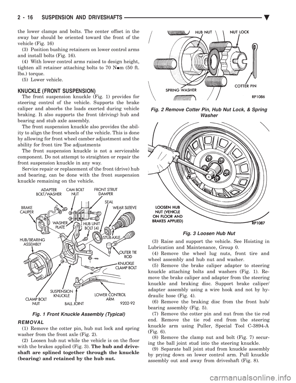
The front suspension knuckle (Fig. 1) provides for
steering control of the vehicle. Supports the brake
caliper and absorbs the loads exerted during vehicle
braking. It also supports the front (driving) hub and
bearing and stub axle assembly. The front suspension knuckle also provides the abil-
ity to align the front wheels of the vehicle. This is done
by allowing for front wheel camber adjustment and the
ability for front tire Toe adjustments The front suspension knuckle is not a serviceable
component. Do not attempt to straighten or repair the
front suspension knuckle in any way. Service repair or replacement of the front (drive) hub
and bearing, can be done with the front suspension
knuckle remaining on the vehicle.
REMOVAL
(1) Remove the cotter pin, hub nut lock and spring
washer from the front axle (Fig. 2). (2) Loosen hub nut while the vehicle is on the floor
with the brakes applied (Fig. 3). The hub and drive-
shaft are splined together through the knuckle
(bearing) and retained by the hub nut. (3) Raise and support the vehicle. See Hoisting in
Lubrication and Maintenance, Group 0. (4) Remove the wheel lug nuts, front tire and
wheel assembly and hub nut and washer. (5) Remove the brake caliper adapter to steering
knuckle attaching bolts and washers (Fig. 1). Re-
move the brake caliper and adapter from the steering
knuckle and braking disc. Support brake caliper/
adapter assembly using a wire hook and not by hy-
draulic hose (Fig. 4). (6) Remove the braking disc from the front hub/
bearing assembly (Fig. 5). (7) Remove the cotter pin and nut from the tie rod
end. Remove the tie rod end from the steering
knuckle arm using Puller, Special Tool C-3894-A
(Fig. 6). (8) Remove the clamp nut and bolt (Fig. 7) secur-
ing the ball joint stud into the steering knuckle. (9) Separate ball joint stud from knuckle assembly
by prying down on lower control arm. Pull knuckle
assembly out and away from driveshaft (Fig. 8).
Fig. 2 Remove Cotter Pin, Hub Nut Lock, & Spring Washer
Fig. 3 Loosen Hub Nut
Fig. 1 Front Knuckle Assembly (Typical)
2 - 16 SUSPENSION AND DRIVESHAFTS Ä
Page 77 of 2438
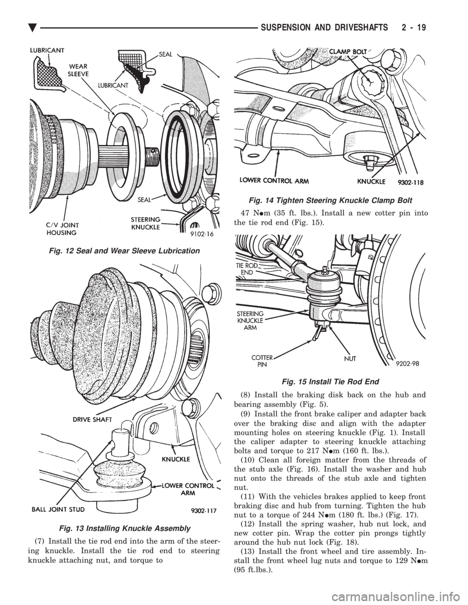
(7) Install the tie rod end into the arm of the steer-
ing knuckle. Install the tie rod end to steering
knuckle attaching nut, and torque to 47 N
Im (35 ft. lbs.). Install a new cotter pin into
the tie rod end (Fig. 15).
(8) Install the braking disk back on the hub and
bearing assembly (Fig. 5). (9) Install the front brake caliper and adapter back
over the braking disc and align with the adapter
mounting holes on steering knuckle (Fig. 1). Install
the caliper adapter to steering knuckle attaching
bolts and torque to 217 N Im (160 ft. lbs.).
(10) Clean all foreign matter from the threads of
the stub axle (Fig. 16). Install the washer and hub
nut onto the threads of the stub axle and tighten
nut. (11) With the vehicles brakes applied to keep front
braking disc and hub from turning. Tighten the hub
nut to a torque of 244 N Im (180 ft. lbs.) (Fig. 17).
(12) Install the spring washer, hub nut lock, and
new cotter pin. Wrap the cotter pin prongs tightly
around the hub nut lock (Fig. 18). (13) Install the front wheel and tire assembly. In-
stall the front wheel lug nuts and torque to 129 N Im
(95 ft.lbs.).
Fig. 13 Installing Knuckle Assembly
Fig. 12 Seal and Wear Sleeve Lubrication
Fig. 14 Tighten Steering Knuckle Clamp Bolt
Fig. 15 Install Tie Rod End
Ä SUSPENSION AND DRIVESHAFTS 2 - 19
Page 78 of 2438
(14) Lower vehicle.
(15) Align the front wheels of the vehicle. Use the
procedure listed under Wheel Alignment, in the
Front Suspension Service Procedures section of this
service manual.
HUB AND BEARING ASSEMBLY
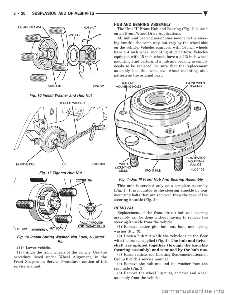
The Unit III Front Hub and Bearing (Fig. 1) is used
on all Front Wheel Drive Applications. All hub and bearing assemblies mount to the steer-
ing knuckle the same way, but very by the wheel size
on the vehicle. Vehicles equipped with 14 inch wheels
have a 4 inch wheel mounting stud pattern. Vehicles
equipped with 15 inch wheels hav e a 4 1/2 inch wheel
mounting stud pattern. If a hub and bearing assembly
needs to be replaced, be sure that the replacement
assembly has the same size wheel mounting stud
pattern as the original part.
This unit is serviced only as a complete assembly
(Fig. 1). It is mounted to the steering knuckle by four
mounting bolts that are removed from the rear of the
steering knuckle (Fig. 2).
REMOVAL
Replacement of the front (drive) hub and bearing
assembly can be done without having to remove the
steering knuckle from the vehicle. (1) Remove cotter pin, hub nut lock, and spring
washer (Fig. 3). (2) Loosen hub nut while the vehicle is on the floor
with the brakes applied (Fig. 4). The hub and drive-
shaft are splined together through the knuckle
(bearing assembly) and retained by the hub nut. (3) Raise vehicle, see Hoisting Recommendations in
Group 0 of this service manual. (4) Remove the hub nut and the washer from the
stub axle (Fig. 3). (5) Remove the wheel lug nuts, and tire and wheel
assembly from the vehicle.
Fig. 16 Install Washer and Hub Nut
Fig. 17 Tighten Hub Nut
Fig. 18 Install Spring Washer, Nut Lock, & Cotter Pin
Fig. 1 Unit III Front Hub And Bearing Assembly
2 - 20 SUSPENSION AND DRIVESHAFTS Ä
Page 82 of 2438
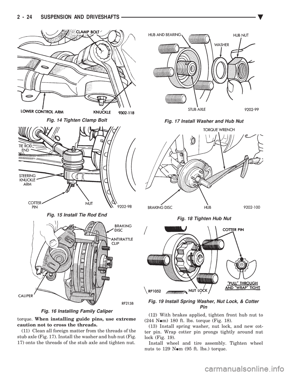
torque. When installing guide pins, use extreme
caution not to cross the threads. (11) Clean all foreign matter from the threads of the
stub axle (Fig. 17). Install the washer and hub nut (Fig.
17) onto the threads of the stub axle and tighten nut. (12) With brakes applied, tighten front hub nut to
(244 N Im) 180 ft. lbs. torque (Fig. 18).
(13) Install spring washer, nut lock, and new cot-
ter pin. Wrap cotter pin prongs tightly around nut
lock (Fig. 19). Install wheel and tire assembly. Tighten wheel
nuts to 129 N Im (95 ft. lbs.) torque.
Fig. 15 Install Tie Rod End
Fig. 16 Installing Family Caliper
Fig. 17 Install Washer and Hub Nut
Fig. 18 Tighten Hub Nut
Fig. 19 Install Spring Washer, Nut Lock, & Cotter
Pin
Fig. 14 Tighten Clamp Bolt
2 - 24 SUSPENSION AND DRIVESHAFTS Ä
Page 85 of 2438
DRIVESHAFT IDENTIFICATION
Driveshafts are identified by the manufacturer. Vehi-
cles can be equipped with any of these driveshaft as-
semblies. Each assembly can be identified as shown in
(Fig. 2).
SERVICE PROCEDURES
Procedures for the removal and installation of the
driveshafts are essentially the same for all front
wheel drive vehicles. Each driveshaft has a spring
within the inboard Tripod C/V joint that maintains
constant engagement with the transaxle. This allows
the drive shaft to be removed without dismantling
part of the transaxle.
CAUTION: Boot sealing is vital to retain special lu-
bricants and to prevent foreign contaminants from
entering the C/V joint. Mishandling, such as allow-
ing the assemblies to dangle unsupported, pulling
or pushing the ends can cut boots or damage C/V
joints. During removal and installation procedures
always support both ends of the driveshaft to pre-
vent damage.
DRIVESHAFTS, REMOVE INSTALL
HUB NUT REMOVAL
Hub nut removal and installation is the same for
all front wheel drive vehicles. For installation see
Hub Nut Assemblies Install. (1) Remove cotter pin, lock and spring washer (Fig.
3).
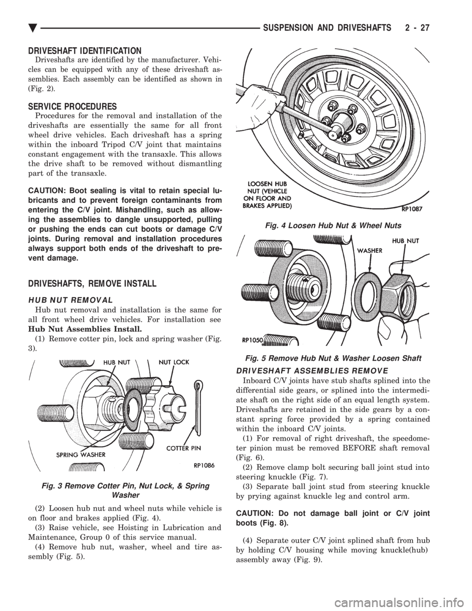
(2) Loosen hub nut and wheel nuts while vehicle is
on floor and brakes applied (Fig. 4). (3) Raise vehicle, see Hoisting in Lubrication and
Maintenance, Group 0 of this service manual. (4) Remove hub nut, washer, wheel and tire as-
sembly (Fig. 5).
DRIVESHAFT ASSEMBLIES REMOVE
Inboard C/V joints have stub shafts splined into the
differential side gears, or splined into the intermedi-
ate shaft on the right side of an equal length system.
Driveshafts are retained in the side gears by a con-
stant spring force provided by a spring contained
within the inboard C/V joints. (1) For removal of right driveshaft, the speedome-
ter pinion must be removed BEFORE shaft removal
(Fig. 6). (2) Remove clamp bolt securing ball joint stud into
steering knuckle (Fig. 7). (3) Separate ball joint stud from steering knuckle
by prying against knuckle leg and control arm.
CAUTION: Do not damage ball joint or C/V joint
boots (Fig. 8). (4) Separate outer C/V joint splined shaft from hub
by holding C/V housing while moving knuckle(hub)
assembly away (Fig. 9).
Fig. 3 Remove Cotter Pin, Nut Lock, & Spring Washer
Fig. 4 Loosen Hub Nut & Wheel Nuts
Fig. 5 Remove Hub Nut & Washer Loosen Shaft
Ä SUSPENSION AND DRIVESHAFTS 2 - 27
Page 88 of 2438
not to allow dirt to enter or grease to leave the boot
cavity. The clamp must be removed and discarded be-
fore the rod can be inserted. After venting, install a
new Service Clamp. (See Boots Install section at the
end of this group for details).
HUB NUT INSTALL
The front wheel hub nuts use a lock and cotter pin
to maintain proper wheel bearing preload and pre-
vent the nut from backing off. Install the assembly
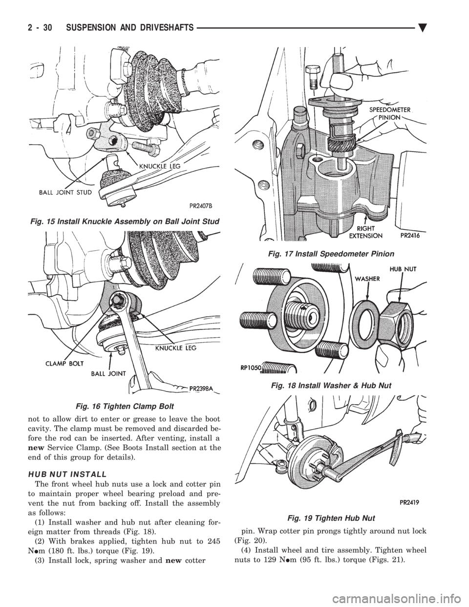
as follows: (1) Install washer and hub nut after cleaning for-
eign matter from threads (Fig. 18). (2) With brakes applied, tighten hub nut to 245
N Im (180 ft. lbs.) torque (Fig. 19).
(3) Install lock, spring washer and newcotter pin. Wrap cotter pin prongs tightly around nut lock
(Fig. 20). (4) Install wheel and tire assembly. Tighten wheel
nuts to 129 N Im (95 ft. lbs.) torque (Figs. 21).
Fig. 15 Install Knuckle Assembly on Ball Joint Stud
Fig. 16 Tighten Clamp Bolt
Fig. 17 Install Speedometer Pinion
Fig. 18 Install Washer & Hub Nut
Fig. 19 Tighten Hub Nut
2 - 30 SUSPENSION AND DRIVESHAFTS Ä
Page 116 of 2438
(3) Install washer and nut. Tighten nut to 27-34
N Im (240-300 in. lbs.) torque while rotating brake
drum. Then back off nut to completely release pre-
load. Finger tighten nut. (4) Position nut lock with one pair of slots in-line
with cotter pin hole. Install cotter pin. Clean and in-
stall grease cap. DISC BRAKE ASSEMBLY
(1) Position caliper support and spindle to axle. In-
stall the 4 spindle mounting bolts finger tight. Then
torque the 4 spindle mounting bolts to 75 N Im (55 ft.
lbs.) torque. (2) Install hub and bearings. (3) Install washer and nut. Tighten to 27-34 N
Im
(240-300 in. lbs.) torque while rotating hub. Then
back off nut to completely release preload. Finger
tighten nut. (4) Position nut lock with one pair of slots in-line
with cotter pin hole. Install cotter pin. Clean and in-
stall grease cap. (5) Install braking disc and adapter. Install caliper
assembly (see Rear Disc Brake) in Brakes Section,
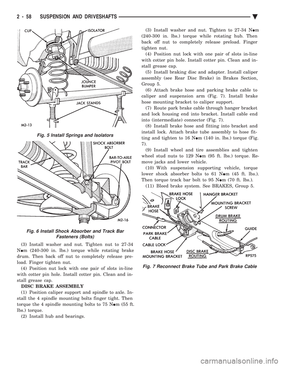
Group 5. (6) Attach brake hose and parking brake cable to
caliper and suspension arm (Fig. 7). Install brake
hose mounting bracket to caliper support. (7) Route park brake cable through hanger bracket
and lock housing end into bracket. Install cable end
into (intermediate) connector (Fig. 7). (8) Install brake hose and fitting into bracket and
install lock. Attach brake tube assembly to hose fit-
ting and tighten to 16 N Im (140 in. lbs.) torque (Fig.
7). (9) Install wheel and tire assemblies and tighten
wheel stud nuts to 129 N Im (95 ft. lbs.) torque. Re-
move jacks and lower vehicle. (10) With suspension supporting vehicle, torque
lower shock absorber bolts to 61 N Im (45 ft. lbs.).
Then torque track bar bolt to 95 N Im (70 ft. lbs.).
(11) Bleed brake system. See BRAKES, Group 5.
Fig. 5 Install Springs and Isolators
Fig. 6 Install Shock Absorber and Track Bar Fasteners (Bolts)
Fig. 7 Reconnect Brake Tube and Park Brake Cable
2 - 58 SUSPENSION AND DRIVESHAFTS Ä
Page 151 of 2438

BRAKES
CONTENTS
page page
ANTI-LOCK BRAKE SYSTEMÐBENDIX ANTI-LOCK 10 AC/Y BODY ............. 72
ANTI-LOCK BRAKE SYSTEMÐBENDIX ANTI-LOCK 6 AA,AG,AJ,AP BODY ....... 113
BRAKE DISC (ROTOR) ................... 53
BRAKE SUPPORT ASSEMBLY ............. 25
FRONT DISC BRAKES ................... 31
GENERAL INFORMATION .................. 1
HYDRAULIC SYSTEM CONTROL VALVES . . . 26
KELSEY HAYES DOUBLE PIN FAMILY CALIPER ............................ 35 KELSEY HAYES DOUBLE PIN NON-FAMILY
CALIPER ............................ 38
MASTER CYLINDER ..................... 66
PARKING BRAKES ...................... 57
POWER BRAKES ....................... 68
REAR DISC BRAKES .................... 45
REAR WHEEL DRUM BRAKES ............ 18
SERVICE ADJUSTMENTS .................. 4
WHEEL BEARINGS ...................... 70
WHEEL CYLINDERS ..................... 23
GENERAL INFORMATION
Throughout this group, references may be made to
a particular vehicle by letter or number designation.
A chart showing the break down of these designa-
tions is included in the Introduction Section at the
front of this service manual. Standard brake equipment consists of:
² Double pin floating caliper disc front brakes.
² Rear automatic adjusting drum brakes.
² Differential valve with a brake warning switch.
² Master cylinder.
² Vacuum power booster.
² Double pin floating caliper rear disc brakes are
available on some models. The Bendix Anti-Lock 10 braking system, uses the
standard power brake system caliper assemblies,
braking discs, pedal assembly, brake lines and hoses.
The unique parts of the Bendix Anti-Lock 10 braking
system consists of the following components. Propor-
tioning valves, wheel speed sensors, tone wheels,
electronic control unit, modulator assembly and hy-
draulic assembly. These components replace the con-
ventional master cylinder and power booster. The
components will be described in detail in the Bendix
Anti-Lock 10 brake section in this group of the ser-
vice manual. The Bendix Anti-Lock 6 braking system, uses the
following standard brake system components. Master
cylinder, power booster, caliper assemblies, braking
discs, pedal assembly, brake lines and hoses. The
unique parts of the Bendix Anti-Lock 6 braking sys-
tem consists of the following components. Modulator
assembly, unique proportioning valves, wheel speed
sensors, tone wheels, and electronic control unit.
These components will be described in detail in the
Bendix Anti-Lock 6 brake section in this group of the
service manual. The front disc brake shoes have semi-metallic lin-
ings. The hydraulic brake system (Fig .123and4)is
diagonally split on both the Non-ABS and ABS brak-
ing system. With the left front and right rear brakes
on one hydraulic system and the right front and left
rear on the other. The Non-ABS and ABS brake system may use dif-
ferent types of brake line fittings and tubing flares.
The Non-ABS brake system uses double wall tubing
flares and fittings at all tubing joint locations. Some
ABS brake systems use both ISO style tubing flares
and double wall tubing flares and corresponding fit-
tings at different joint locations. See (Figs . 2 3 and 4)
for specific joint locations and type of tubing flare. The front disc brakes consist of two different types
of caliper assemblies. A double pin Kelsey-Hayes cal-
iper (family caliper) with a bolt-on adapter attached
to the steering knuckle. Or a double pin Kelsey-
Hayes caliper (non-family caliper) which mounts di-
rectly to rails on the steering knuckle. The non-
family caliper is only used on the AY Body
(Imperials).
CAUTION: Caliper pistons, boots and seals for the
different caliper assemblies used on the front and
rear disc brake assemblies are not interchangeable.
Misusage could result in a complete brake system
failure. Be sure that the parts are replaced with the
correct replacement parts, refer to the parts book
for the type and model year of the vehicle being
worked on.
The master cylinder is anodized, lightweight alu-
minum, with a bore size of 24.0mm, 21.0mm or 7/8
inch.
Ä BRAKES 5 - 1