1993 CHEVROLET DYNASTY brakes
[x] Cancel search: brakesPage 1825 of 2438
² Manifold Absolute Pressure (MAP) Sensor
² Oxygen Sensor
² SCI Receive
² Speed Control System Controls
² Throttle Position Sensor
² Vehicle Speed Sensor
PCM Outputs:
² Air Conditioning Clutch Relay
² Generator Field
² Idle Air Control Motor
² Auto Shutdown (ASD) Relay
² Barometric Read Solenoid
² Canister Purge Solenoid
² Malfunction Indicator Lamp (Check Engine Lamp)
² Data Link Connector
² Fuel Injectors
² Ignition Coil
² Radiator Fan Relay
² Speed Control Solenoids
² Tachometer Output
² Wastegate Solenoid
Based on inputs it receives, the PCM adjusts fuel
injector pulse width, idle speed, ignition spark ad-
vance, ignition coil dwell and canister purge opera-
tion. The PCM regulates operation of the cooling fan,
A/C and speed control systems. The PCM changes
generator charge rate by adjusting the generator
field. The PCM adjusts injector pulse width (air-fuel ra-
tio) based on the following inputs.
² battery voltage
² engine coolant temperature
² exhaust gas content
² engine speed (crankshaft position sensor)
² manifold absolute pressure
² throttle position
The PCM adjusts ignition timing based on the fol-
lowing inputs.
² engine coolant temperature
² knock sensor
² engine speed (crankshaft position sensor)
² manifold absolute pressure
² throttle position
The Automatic Shut Down (ASD) and Fuel Pump
relays are mounted externally, but turned on and off
by the PCM through the same circuit. The camshaft position sensor and crankshaft posi-
tion sensor signals are sent to the PCM. If the PCM
does not receive both signals within approximately
one second of engine cranking, it deactivates the
ASD relay and fuel pump relay. When these relays
are deactivated, power is shut off to the fuel injector,
ignition coil, oxygen sensor heating element and fuel
pump. The PCM contains a voltage converter that
changes battery voltage to a regulated 8.0 volts. The
8.0 volts power the camshaft position sensor, crank- shaft position sensor and vehicle speed sensor. The
PCM also provides a 5.0 volts supply for the coolant
temperature sensor, manifold absolute pressure sen-
sor and throttle position sensor.
AIR CONDITIONING SWITCH SENSEÐPCM INPUT
When the air conditioning or defrost switch is put
in the ON position and the low pressure and high
pressure switches are closed, the PCM receives an in-
put for air conditioning. After receiving this input,
the PCM activates the A/C compressor clutch by
grounding the A/C clutch relay. The PCM also ad-
justs idle speed to a scheduled RPM to compensate
for increased engine load.
BATTERY VOLTAGEÐPCM INPUT
The PCM monitors the battery voltage input to de-
termine fuel injector pulse width and generator field
control. If battery voltage is low the PCM will in-
crease injector pulse width (period of time that the
injector is energized).
BRAKE SWITCHÐPCM INPUT
When the brake switch is activated, the PCM re-
ceives an input indicating that the brakes are being
applied. After receiving this input, the PCM vents
the speed control servo. Venting the servo turns the
speed control system off. The brake switch is
mounted on the brake pedal support bracket.
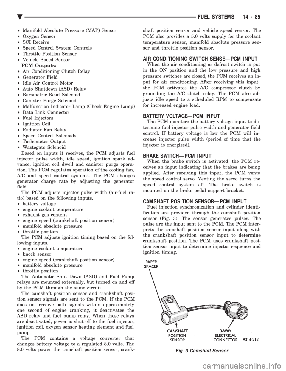
CAMSHAFT POSITION SENSORÐPCM INPUT
Fuel injection synchronization and cylinder identi-
fication are provided through the camshaft position
sensor (Fig. 3). The sensor generates pulses. The
pulse are the input sent to the PCM. The PCM inter-
prets the camshaft position sensor input along with
the crankshaft position sensor input to determine
crankshaft position. The PCM uses crankshaft posi-
tion sensor input to determine injector sequence and
ignition timing.
Fig. 3 Camshaft Sensor
Ä FUEL SYSTEMS 14 - 85
Page 1855 of 2438
The PCM adjusts ignition timing based on the fol-
lowing inputs.
² engine coolant temperature
² engine speed (distributor pick-up)
² manifold absolute pressure
² throttle position
The Automatic Shut Down (ASD) and Fuel Pump
relays are mounted externally, but turned on and off
by the PCM through the same circuit. The distributor pick-up signal is sent to the PCM.
If the PCM does not receive a distributor signal
within approximately one second of engine cranking,
the ASD relay and fuel pump relay are deactivated.
When these relays are deactivated, power is shut off
to the fuel injector, ignition coil, oxygen sensor heat-
ing element and fuel pump. The PCM contains a voltage converter that
changes battery voltage to a regulated 8.0 volts. The
8.0 volts power the distributor pick-up and vehicle
speed sensor. The PCM also provides a 5.0 volts sup-
ply for the coolant temperature sensor, manifold ab-
solute pressure sensor and throttle position sensor.
AIR CONDITIONING SWITCH SENSE (AA, AG, AJ
BODY)ÐPCM INPUT
When the air conditioning or defrost switch is in
the ON position and the low pressure and high pres-
sure switches are closed, the PCM receives an input
for air conditioning. After receiving this input, the
PCM activates the A/C compressor clutch by ground-
ing the A/C clutch relay. The PCM also adjusts idle
speed to a scheduled RPM to compensate for in-
creased engine load.
AIR CONDITIONING SWITCH SENSE (AC
BODY)ÐPCM INPUT
When the air conditioning or defrost switch is in
the ON position and the low pressure, high pressure
and ambient temperature switches are closed, the
PCM receives an input for air conditioning. After re-
ceiving this input, the PCM activates the A/C com-
pressor clutch by grounding the A/C clutch relay.
The PCM also adjusts idle speed to a scheduled RPM
to compensate for increased engine load.
BATTERY VOLTAGEÐPCM INPUT
The PCM monitors the battery voltage input to de-
termine fuel injector pulse width and generator field
control. If battery voltage is low, the PCM will in-
crease injector pulse width.
BRAKE SWITCHÐPCM INPUT
When the brake switch is activated, the PCM re-
ceives an input indicating that the brakes are being
applied. After receiving this input the PCM main-
tains idle speed to a scheduled RPM through the idle
air control motor. The brake switch is mounted on
the brake pedal support bracket.
ENGINE COOLANT TEMPERATURE SENSORÐPCM
INPUT
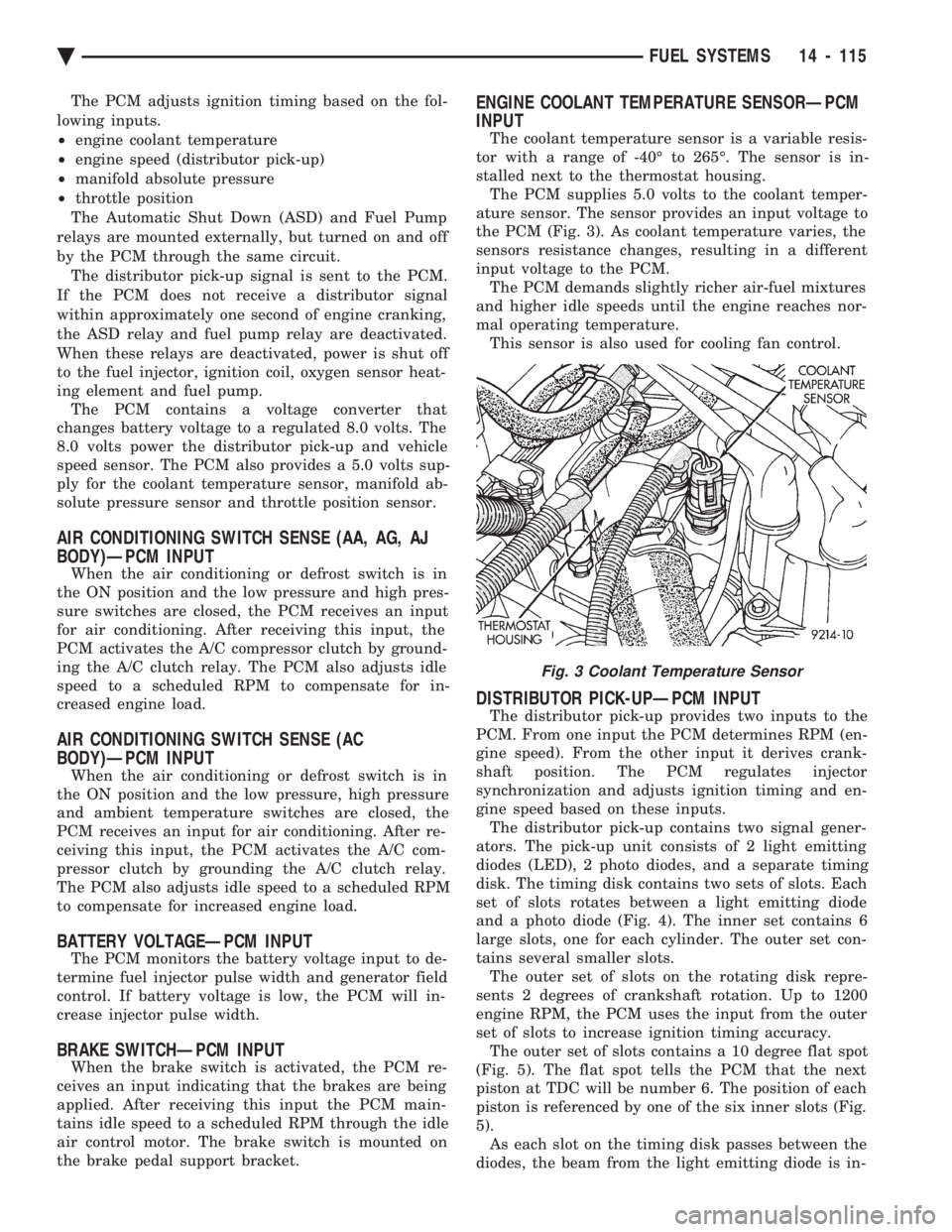
The coolant temperature sensor is a variable resis-
tor with a range of -40É to 265É. The sensor is in-
stalled next to the thermostat housing. The PCM supplies 5.0 volts to the coolant temper-
ature sensor. The sensor provides an input voltage to
the PCM (Fig. 3). As coolant temperature varies, the
sensors resistance changes, resulting in a different
input voltage to the PCM. The PCM demands slightly richer air-fuel mixtures
and higher idle speeds until the engine reaches nor-
mal operating temperature. This sensor is also used for cooling fan control.
DISTRIBUTOR PICK-UPÐPCM INPUT
The distributor pick-up provides two inputs to the
PCM. From one input the PCM determines RPM (en-
gine speed). From the other input it derives crank-
shaft position. The PCM regulates injector
synchronization and adjusts ignition timing and en-
gine speed based on these inputs. The distributor pick-up contains two signal gener-
ators. The pick-up unit consists of 2 light emitting
diodes (LED), 2 photo diodes, and a separate timing
disk. The timing disk contains two sets of slots. Each
set of slots rotates between a light emitting diode
and a photo diode (Fig. 4). The inner set contains 6
large slots, one for each cylinder. The outer set con-
tains several smaller slots. The outer set of slots on the rotating disk repre-
sents 2 degrees of crankshaft rotation. Up to 1200
engine RPM, the PCM uses the input from the outer
set of slots to increase ignition timing accuracy. The outer set of slots contains a 10 degree flat spot
(Fig. 5). The flat spot tells the PCM that the next
piston at TDC will be number 6. The position of each
piston is referenced by one of the six inner slots (Fig.
5). As each slot on the timing disk passes between the
diodes, the beam from the light emitting diode is in-
Fig. 3 Coolant Temperature Sensor
Ä FUEL SYSTEMS 14 - 115
Page 1868 of 2438
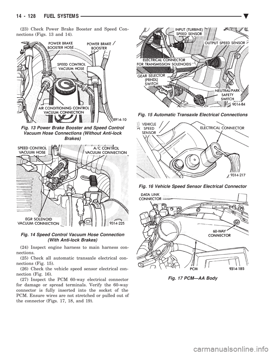
(23) Check Power Brake Booster and Speed Con-
nections (Figs. 13 and 14).
(24) Inspect engine harness to main harness con-
nections. (25) Check all automatic transaxle electrical con-
nections (Fig. 15). (26) Check the vehicle speed sensor electrical con-
nection (Fig. 16). (27) Inspect the PCM 60-way electrical connector
for damage or spread terminals. Verify the 60-way
connector is fully inserted into the socket of the
PCM. Ensure wires are not stretched or pulled out of
the connector (Figs. 17, 18, and 19).
Fig. 13 Power Brake Booster and Speed Control Vacuum Hose Connections (Without Anti-lock Brakes)
Fig. 14 Speed Control Vacuum Hose Connection(With Anti-lock Brakes)
Fig. 15 Automatic Transaxle Electrical Connections
Fig. 16 Vehicle Speed Sensor Electrical Connector
Fig. 17 PCMÐAA Body
14 - 128 FUEL SYSTEMS Ä
Page 1887 of 2438
² transaxle gear selection (park/neutral switch)
The PCM also adjusts engine idle speed through
the idle air control motor based on the following in-
puts.
² brake switch
² engine coolant temperature
² engine speed (crankshaft position sensor)
² throttle position
² transaxle gear selection (park/neutral switch)
² vehicle speed
The auto shutdown (ASD) and fuel pump relays are
mounted externally, but turned on and off by the
PCM through the same circuit. The camshaft position sensor and crankshaft posi-
tion sensor signals are sent to the PCM. If the PCM
does not receive both signals within approximately
one second of engine cranking, it deactivates the
ASD and fuel pump relays. When these relays are
deactivated, power is shut off to the fuel injector, ig-
nition coil, oxygen sensor heating element and fuel
pump. The PCM contains a voltage converter that
changes battery voltage to a regulated 8.0 volts. The
8.0 volts power the camshaft position sensor, crank-
shaft position sensor and vehicle speed sensor. The
PCM also provides a 5.0 volts supply for the coolant
temperature sensor, manifold absolute pressure sen-
sor and throttle position sensor.
AIR CONDITIONING SWITCH SENSEÐPCM INPUT
When the air conditioning or defrost switch is put
in the ON position and the low pressure, high pres-
sure and ambient temperature switches are closed,
the PCM receives an input for air conditioning. After
receiving this input, the PCM activates the A/C com-
pressor clutch by grounding the A/C clutch relay.
BATTERY VOLTAGEÐPCM INPUT
The PCM monitors the battery voltage input to de-
termine fuel injector pulse width and generator field
control. If battery voltage is low the PCM will in-
crease injector pulse width.
BRAKE SWITCHÐPCM INPUT
When the brake switch is activated, the PCM re-
ceives an input indicating that the brakes are being
applied. the brake signal cancels speed control and
unlocks the torque convertor. The brake switch is
mounted on the brake pedal support bracket.
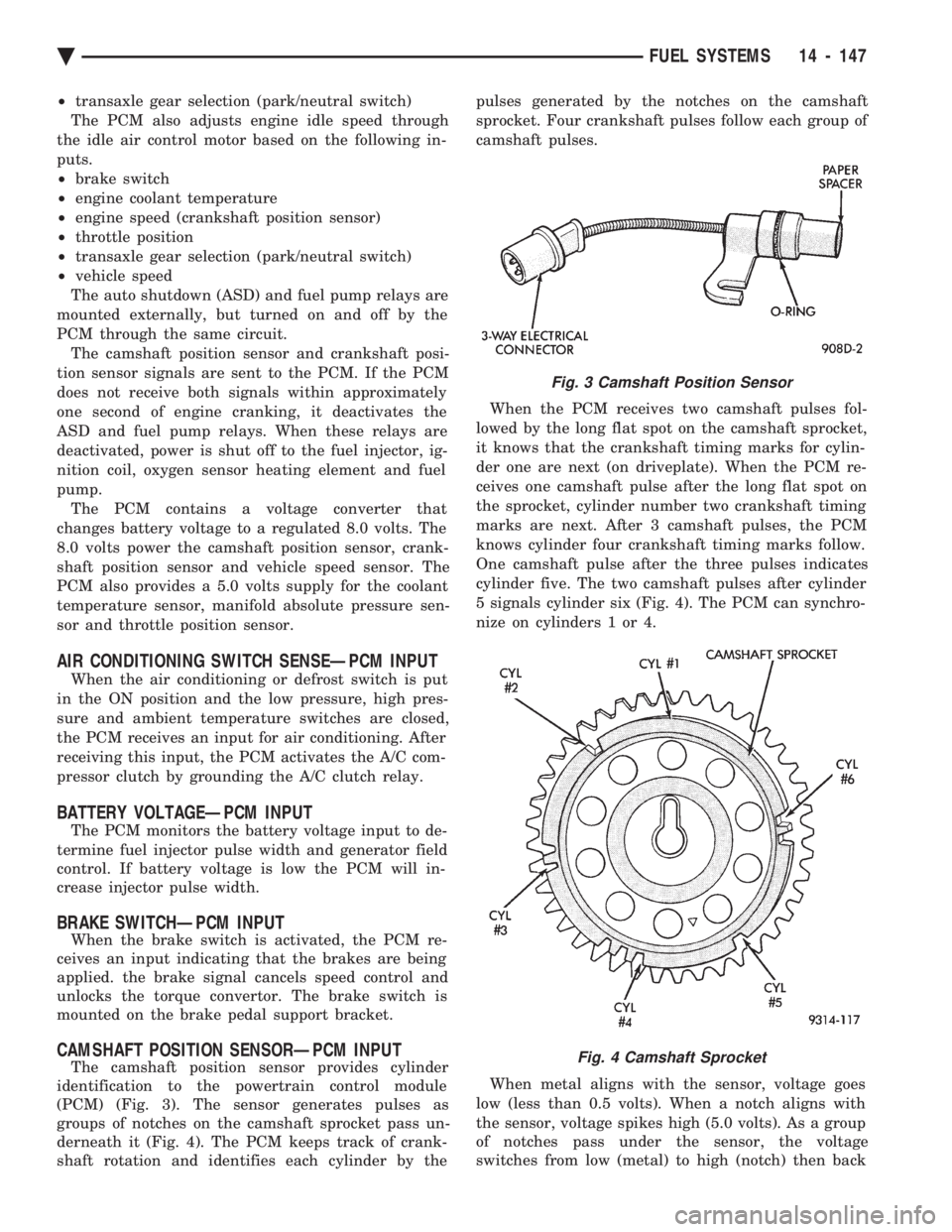
CAMSHAFT POSITION SENSORÐPCM INPUT
The camshaft position sensor provides cylinder
identification to the powertrain control module
(PCM) (Fig. 3). The sensor generates pulses as
groups of notches on the camshaft sprocket pass un-
derneath it (Fig. 4). The PCM keeps track of crank-
shaft rotation and identifies each cylinder by the pulses generated by the notches on the camshaft
sprocket. Four crankshaft pulses follow each group of
camshaft pulses.
When the PCM receives two camshaft pulses fol-
lowed by the long flat spot on the camshaft sprocket,
it knows that the crankshaft timing marks for cylin-
der one are next (on driveplate). When the PCM re-
ceives one camshaft pulse after the long flat spot on
the sprocket, cylinder number two crankshaft timing
marks are next. After 3 camshaft pulses, the PCM
knows cylinder four crankshaft timing marks follow.
One camshaft pulse after the three pulses indicates
cylinder five. The two camshaft pulses after cylinder
5 signals cylinder six (Fig. 4). The PCM can synchro-
nize on cylinders 1 or 4.
When metal aligns with the sensor, voltage goes
low (less than 0.5 volts). When a notch aligns with
the sensor, voltage spikes high (5.0 volts). As a group
of notches pass under the sensor, the voltage
switches from low (metal) to high (notch) then back
Fig. 3 Camshaft Position Sensor
Fig. 4 Camshaft Sprocket
Ä FUEL SYSTEMS 14 - 147
Page 2000 of 2438
FLUID LEVEL AND CONDITION
The transmission and differential sump have a
common oil sump with a communicating opening
between the two. Before removing the dipstick, wipe all dirt off of the
protective disc and the dipstick handle. The torque converter will fill in both the PPark or N
Neutral positions. Place the selector lever in PPark to
check fluid level. Inspect fluid level on dipstick every six months.
Allow the engine to idle for at least one minute
with vehicle on level ground. This will assure
complete oil level stabilization between differen-
tial and transmission. A properly filled transaxle
will read near the addmark when fluid temperature is
21 degrees Celsius (70 degrees Fahrenheit). When the
transaxle reaches operating temperature the fluid
should be in the HOTregion.
Low fluid level can cause a variety of conditions
because it allows the pump to take in air along with the
fluid. As in any hydraulic system, air bubbles make the
fluid spongy, therefore, pressures will be low and build
up slowly. Improper filling can also raise the fluid level too
high. When the transaxle has too much fluid, the gears
churn up foam and cause the same conditions which
occur with a low fluid level. In either case, the air bubbles can cause overheating,
fluid oxidation, and varnishing, which can interfere
with normal valve, clutch, and servo operation. Foam-
ing can also result in fluid escaping from the transaxle
vent (dipstick handle) where it may be mistaken for a
leak. Along with fluid level, it is important to check the
condition of the fluid. When the fluid smells burned,
and is contaminated with metal or friction material
particles, a complete transaxle overhaul is needed. Be
sure to examine the fluid on the dipstick closely. If
there is any doubt about its condition, drain out a
sample for a double check. After the fluid has been checked, seat the dipstick
fully to seal out water and dirt.
SELECTION OF LUBRICANT
It is important that the proper lubricant be used in
these transmissions. MOPAR tATF PLUS (Automatic
Transmission Fluid-Type 7176) should be used to aid in
assuring optimum transmission performance. Fluids of
the type labeled DEXRON II Automatic Transmission
Fluid should be used only if the recommended fluid is
not available. It is important that the transmission
fluid be maintained at the prescribed level using the
recommended fluids.
SPECIAL ADDITIVES
Chrysler Corporation does not recommend the addi-
tion of any fluids to the transmission, other than the
automatic transmission fluid listed above. An ex- ception to this policy is the use of special dyes to aid in
detecting fluid leaks. The use of transmission sealers
should be avoided, since they may adversely affect
seals.
FLUID AND FILTER CHANGE
When the factory fill fluid is changed, only
fluids of the type labeled MOPAR tATF PLUS
(Automatic Transmission fluid) Type 7176 should
be used. A band adjustment and filter change
should be made at the time of the oil change. The
magnet (on the inside of the oil pan) should also
be cleaned with a clean, dry cloth. If the transaxle is disassembled for any reason,
the fluid and filter should be changed, and the
band(s) adjusted.
FLUID DRAIN AND REFILL
(1) Raise vehicle on a hoist (See Lubrication, Group
0). Place a drain container with a large opening, under
transaxle oil pan. (2) Loosen pan bolts and tap the pan at one corner to
break it loose allowing fluid to drain, then remove the
oil pan. (3) Install a new filter and gasket on bottom of the
valve body and tighten retaining screws to 5 N Im (40
in. lbs.). (4) Clean the oil pan and magnet. Reinstall pan
using new MOPAR tAdhesive sealant. Tighten oil pan
bolts to 19 N Im (165 in. lbs.).
(5) Pour four quarts of MOPAR tATF PLUS (Auto-
matic Transmission Fluid) Type 7176 through the
dipstick opening. (6) Start engine and allow to idle for at least one
minute. Then, with parking and service brakes ap-
plied, move selector lever momentarily to each posi-
tion, ending in the park or neutral position. (7) Add sufficient fluid to bring level to 1/8 inch
below the ADD mark. Recheck fluid level after transaxle is at normal
operating temperature. The level should be in the HOT
region (Fig. 1). To prevent dirt from entering transaxle, make cer-
tain that dipstick is full seated into the dipstick open-
ing.
TORQUE CONVERTER CLUTCH SOLENOID WIRING
CONNECTOR
If wiring connector is unplugged, the torque con-
verter clutch will not operate (Fig. 2).
ROAD TEST
Prior to performing a road test, be certain that the
fluid level and condition, and control cable adjustments
have been checked and approved. During the road test, the transaxle should be oper-
ated in each position to check for slipping and any
variation in shifting.
21 - 40 TRANSAXLE Ä
Page 2053 of 2438
FLUID LEVEL AND CONDITION
The transmission and differential sump have a
common oil sump with a communicating opening
between the two. The torque converter fills in both the PPark and N
Neutral positions. Place the selector lever in PPark to
check the fluid level. The engine should be running
at idle speed for at least one minute, with the
vehicle on level ground. This will assure com-
plete oil level stabilization between differential
and transmission. The fluid should be at normal
operating temperature (approximately 82 C. or 180 F.).
The fluid level is correct if it is in the HOTregion
(cross-hatched area) on the oil level indicator. Low fluid level can cause a variety of conditions
because it allows the pump to take in air along with the
fluid. As in any hydraulic system, air bubbles make the
fluid spongy, therefore, pressures will be low and build
up slowly. Improper filling can also raise the fluid level too
high. When the transaxle has too much fluid, the gears
churn up foam and cause the same conditions which
occur with a low fluid level. In either case, the air bubbles can cause over heat-
ing, fluid oxidation, and varnishing, which can inter-
fere with normal valve, clutch, and accumulator opera-
tion. Foaming can also result in fluid escaping from the
transaxle vent where it may be mistaken for a leak. Along with fluid level, it is important to check the
condition of the fluid. When the fluid smells burned,
and is contaminated with metal or friction material
particles, a complete transaxle overhaul is needed. Be
sure to examine the fluid on the dipstick closely. If
there is any doubt about its condition, drain out a
sample for a double check. After the fluid has been checked, seat the dipstick
fully to seal out water and dirt.
SELECTION OF LUBRICANT
It is important that the proper lubricant be used in
the 41TE transaxle. MOPAR tATF PLUS (Automatic
Transmission FluidÐtype 7176) should be used to aid
in assuring optimum transmission performance. Flu-
ids of the type labeled DEXRON II Automatic Trans-
mission Fluid are not recommended . DEXRON II
can be used only if the recommended fluid is not
available. If more than a small amount of DEXRON II
is used shudder or shift quality problems may result. It
is important that the transmission fluid be maintained
at the prescribed level using the recommended fluids.
SPECIAL ADDITIVES
Chrysler Corporation does not recommend the addi-
tion of any fluids to the transaxle, other than the
automatic transmission fluid listed above. An excep- tion to this policy is the use of special dyes to aid in
detecting fluid leaks. The use of transmission sealers
should be avoided, since they may adversely affect
seals.
FLUID AND FILTER CHANGES
When the factory fill fluid is changed, only fluids
labeled MOPAR tATF PLUS (Automatic Transmis-
sion fluid) Type 7176 should be used. A filter change
should be made at the time of the oil change. Also
the magnet (on the inside of the oil pan) should be
cleaned with a clean, dry cloth. If the transaxle is disassembled for any reason, the
fluid and filter should be changed.
FLUID DRAIN AND REFILL
(1) Raise vehicle on a hoist (See Lubrication,
Group 0). Place a drain container with a large open-
ing, under transaxle oil pan. (2) Loosen pan bolts and tap the pan at one corner
to break it loose allowing fluid to drain, then remove
the oil pan. (3) Install a new filter and O-ring on bottom of the
valve body. (4) Clean the oil pan and magnet. Reinstall pan
using new MOPAR tAdhesive Sealant. Tighten oil
pan bolts to 19 N Im (165 in. lbs.).
(5) Pour four quarts of MOPAR tATF PLUS (Au-
tomatic Transmission Fluid) Type 7176 through the
fill tube. (6) Start engine and allow to idle for at least one
minute. Then, with parking and service brakes ap-
plied, move selector lever momentarily to each posi-
tion, ending in the park or neutral position. (7) Add sufficient fluid to bring level to 1/8 inch
below the ADD mark. Recheck fluid level after transaxle is at normal op-
erating temperature. The level should be in the HOT
region (Fig. 3).
To prevent dirt from entering transaxle, make cer-
tain that dipstick is seated into the dipstick fill tube
(Fig. 4).
ROAD TEST
Prior to performing a road test, be certain that the
fluid level and condition, and control cable adjust-
ment have been checked and approved.
Fig. 3 Oil Level Indicator
Ä TRANSAXLE 21 - 93
Page 2149 of 2438
WHEELSÐTIRES
CONTENTS
page page
SPECIFICATIONS ........................ 8
TIRE SERVICE PROCEDURES .............. 1 WHEELS SERVICE PROCEDURES
........... 6
TIRE SERVICE PROCEDURES INDEX
page page
Cleaning of Tires .......................... 1
General Information ........................ 1
Pressure Gauges ......................... 2
Radial-Ply Tires ........................... 1
Repairing Leaks .......................... 3
Rotation ................................ 3 Spare TireÐCompact
...................... 1
Tire Inflation Pressures ..................... 2
Tire Noise or Vibration ..................... 3
Tire Wear Patterns ........................ 3
Tread Wear Indicators ...................... 3
GENERAL INFORMATION
Throughout this group, references may be made to a
particular vehicle by letter or number designation. A
chart showing the breakdown of these designations is
included in the Introduction Section. Tires are designed for the vehicle and provide the
best overall performance for normal operation. The
ride and handling characteristics match the vehicle's
requirements. With proper care they will give excellent
reliability traction, skid resistance and tread life. They
have load carrying capacity, when properly inflated, to
operate at loads up to the specified Maximum Vehicle
Capacity. Driving habits have more effect on tire life than any
other factor. Careful drivers will obtain, in most cases,
much greater mileage than severe or careless drivers. A
few of the driving habits which will shorten the life of
any tire are:
² Rapid acceleration and deceleration
² Severe application of brakes
² High-speed driving
² Taking turns at excessive speeds
² Striking curbs and other obstacles
Radial ply tires can be more susceptible to irregular
tread wear. It is very important to follow the tire
rotation interval shown in the section on Tire
Rotation to achieve a greater tread life potential.
RADIAL-PLY TIRES
Radial-ply tires improve handling, tread life, and
ride quality and decrease rolling resistance. Radial-ply tires must always be used in sets of four
and under no circumstances should they be used on
the front only. However, they may be mixed with temporary spare tires when necessary,
but reduced speeds are recommended. Radial-ply tires have the same load carrying capac-
ity as other types of tires of the same size. They also
use the same recommended inflation pressures.
SPARE TIREÐCOMPACT
The compact spare tire is designed for emergency
use only. The original tire should be repaired and re-
installed at the first opportunity. Refer to Owner's
Manual for complete details.
TIRE CHAINS
Tire snow chains may be used on certainmodels.
Refer to Owner's Manual for more information.
CLEANING OF TIRES
Remove protective coating on tires before delivery
of vehicle, otherwise it could cause deterioration of
tires. Remove protective coating by applying warm wa-
ter, letting it soak one minute, and then scrubbing
the coating away with a soft bristle brush. Steam cleaning may also be used for cleaning.
DO NOT use gasoline or wire brush for cleaning.
DO NOT use mineral oil or an oil-based solvent.
Ä WHEELSÐTIRES 22 - 1