1993 CHEVROLET DYNASTY brakes
[x] Cancel search: brakesPage 168 of 2438
REAR WHEEL DRUM BRAKES INDEX
page page
Brake Drum Refacing ..................... 21
Brake Shoe Assemblies ................... 19 Description
............................. 18
Service Procedures ....................... 18
DESCRIPTION
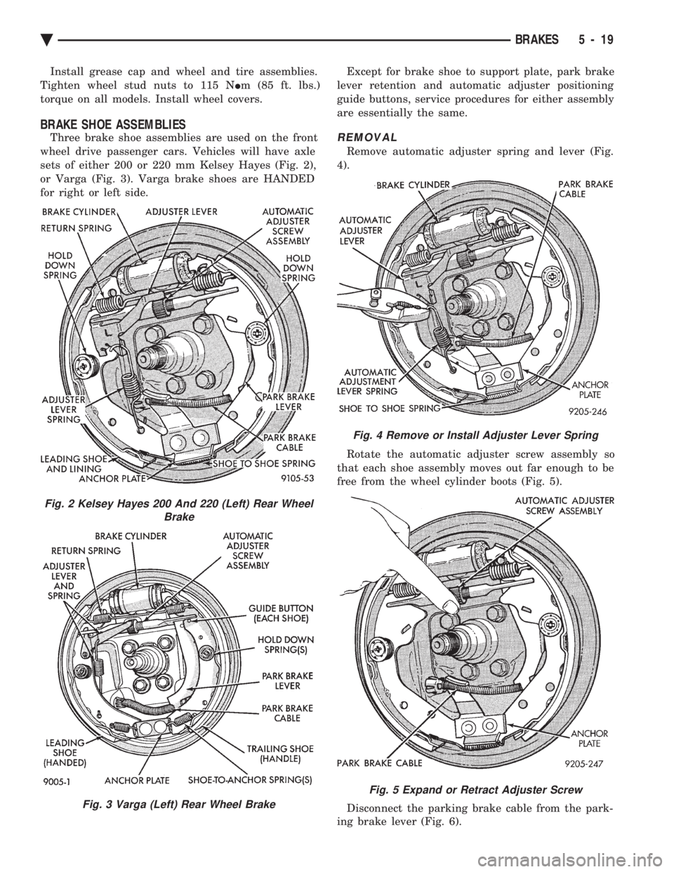
Rear wheel drum brakes (Fig .2&3)aretwoshoe,
internal expanding type with an automatic adjuster
screw assembly that is activated each time the
brakes are applied. The automatic adjuster screw is
located directly below the wheel cylinder as shown in
figure (Fig .2&3).
WARNING: DUST AND DIRT ON BRAKE PARTS
GENERATED DURING THE NORMAL USE AND
WEAR OF MOTOR VEHICLE BRAKE SYSTEMS MAY
CONTAIN ASBESTOS FIBERS. BREATHING EXCES-
SIVE CONCENTRATIONS OF ASBESTOS FIBERS
CAN CAUSE SERIOUS BODILY HARM, SUCH AS
ASBESTOSIS AND CANCER. EXTREME CARE
SHOULD BE EXERCISED WHILE SERVICING
BRAKE ASSEMBLIES OR COMPONENTS. DO NOT CLEAN BRAKE ASSEMBLIES OR COM-
PONENTS WITH COMPRESSED AIR OR BY DRY
BRUSHING; USE A VACUUM CLEANER SPECIFI-
CALLY RECOMMENDED FOR USE WITH ASBES-
TOS FIBERS. IF A SUITABLE VACUUM CLEANER IS
NOT AVAILABLE, CLEANING SHOULD BE DONE
WET USING A WATER DAMPENED CLOTH. DO NOT CREATE DUST BY SANDING, GRINDING,
AND/OR SHAVING BRAKE LININGS OR PADS UN-
LESS SUCH OPERATION IS DONE WHILE USING
PROPERLY EXHAUST VENTILATED EQUIPMENT. DISPOSE OF ALL DUST AND DIRT SUSPECTED
TO CONTAIN ANY ASBESTOS FIBERS IN SEALED
BAGS OR CONTAINERS TO MINIMIZE DUST EXPO-
SURE TO YOURSELF AND OTHERS. FOLLOW ALL RECOMMENDED PRACTICES PRE-
SCRIBED BY THE OCCUPATIONAL SAFETY AND
HEALTH ADMINISTRATION AND THE ENVIRON-
MENTAL PROTECTION AGENCY. FOR THE HAN-
DLING, PROCESSING, AND DISPOSITION OF DUST
OR DIRT WHICH MAY CONTAIN ASBESTOS FI-
BERS. IT IS RECOMMENDED NOT TO BREATH ANY
TYPE OF BRAKE LINING MATERIAL DUST EVEN
ASBESTOS FREE, DUE TO THE FIBROUS NATURE
OF THE MATERIALS BEING USED.
SERVICE PROCEDURES
REAR BRAKE DRUM REMOVAL
If the rear brake drum is difficult to remove, fur-
ther clearance can be obtained by backing off the
brake automatic adjuster screw. Remove rubber plug
from the top of the support plate and rotate the au-
tomatic adjuster screw assembly with an upward mo-
tion, using the Brake Adjuster, Special Tool C-3784. See adjusting rear service brakes in the Service
Adjustments section in this group of the service man-
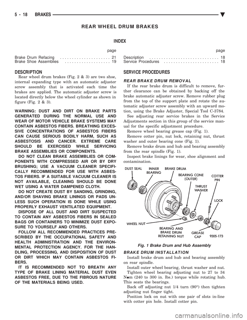
ual for the specific adjustment procedure. Remove wheel bearing grease cap (Fig. 1).
Remove cotter pin, nut lock, retaining nut, thrust
washer and outer bearing cone (Fig. 1). Remove brake drum and hub and bearing assembly
from the rear spindle (Fig. 1). Inspect brake linings for wear, shoe alignment and
contamination.
BRAKE DRUM INSTALLATION
Install brake drum and hub and bearing assembly
on rear spindle. Install outer wheel bearing, thrust washer and nut.
Tighten wheel bearing adjusting nut to 27 to 34
N Im (240 to 300 in. lbs.) torque while rotating hub.
This seats the bearings. Back off adjusting nut 1/4 turn (90É) then tighten
adjusting nut finger tight. Position lock on nut with one pair of slots in-line
with cotter pin hole. Install cotter pin.
Fig. 1 Brake Drum and Hub Assembly
5 - 18 BRAKES Ä
Page 169 of 2438
Install grease cap and wheel and tire assemblies.
Tighten wheel stud nuts to 115 N Im (85 ft. lbs.)
torque on all models. Install wheel covers.
BRAKE SHOE ASSEMBLIES
Three brake shoe assemblies are used on the front
wheel drive passenger cars. Vehicles will have axle
sets of either 200 or 220 mm Kelsey Hayes (Fig. 2),
or Varga (Fig. 3). Varga brake shoes are HANDED
for right or left side. Except for brake shoe to support plate, park brake
lever retention and automatic adjuster positioning
guide buttons, service procedures for either assembly
are essentially the same.REMOVAL
Remove automatic adjuster spring and lever (Fig.
4).
Rotate the automatic adjuster screw assembly so
that each shoe assembly moves out far enough to be
free from the wheel cylinder boots (Fig. 5).
Disconnect the parking brake cable from the park-
ing brake lever (Fig. 6).
Fig. 2 Kelsey Hayes 200 And 220 (Left) Rear Wheel Brake
Fig. 3 Varga (Left) Rear Wheel Brake
Fig. 4 Remove or Install Adjuster Lever Spring
Fig. 5 Expand or Retract Adjuster Screw
Ä BRAKES 5 - 19
Page 170 of 2438
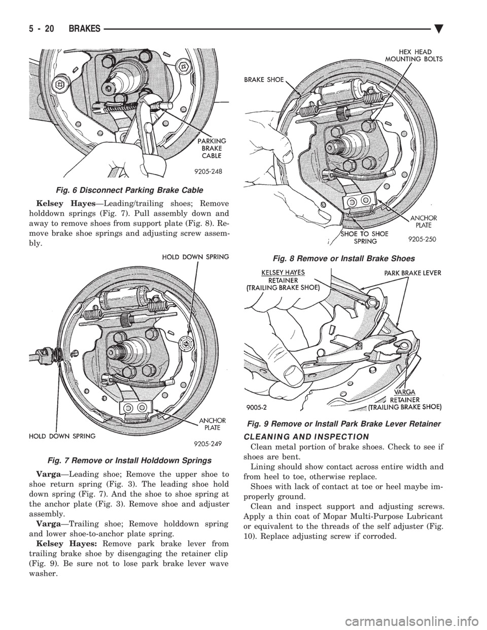
Kelsey Hayes ÐLeading/trailing shoes; Remove
holddown springs (Fig. 7). Pull assembly down and
away to remove shoes from support plate (Fig. 8). Re-
move brake shoe springs and adjusting screw assem-
bly.
Varga ÐLeading shoe; Remove the upper shoe to
shoe return spring (Fig. 3). The leading shoe hold
down spring (Fig. 7). And the shoe to shoe spring at
the anchor plate (Fig. 3). Remove shoe and adjuster
assembly. Varga ÐTrailing shoe; Remove holddown spring
and lower shoe-to-anchor plate spring. Kelsey Hayes: Remove park brake lever from
trailing brake shoe by disengaging the retainer clip
(Fig. 9). Be sure not to lose park brake lever wave
washer.
CLEANING AND INSPECTION
Clean metal portion of brake shoes. Check to see if
shoes are bent. Lining should show contact across entire width and
from heel to toe, otherwise replace. Shoes with lack of contact at toe or heel maybe im-
properly ground. Clean and inspect support and adjusting screws.
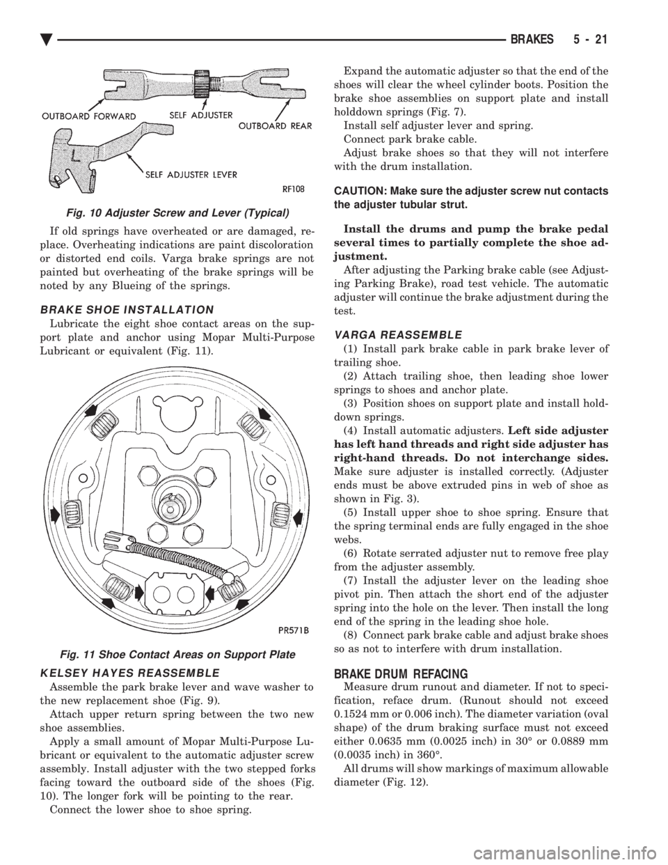
Apply a thin coat of Mopar Multi-Purpose Lubricant
or equivalent to the threads of the self adjuster (Fig.
10). Replace adjusting screw if corroded.
Fig. 6 Disconnect Parking Brake Cable
Fig. 7 Remove or Install Holddown Springs
Fig. 8 Remove or Install Brake Shoes
Fig. 9 Remove or Install Park Brake Lever Retainer
5 - 20 BRAKES Ä
Page 171 of 2438
If old springs have overheated or are damaged, re-
place. Overheating indications are paint discoloration
or distorted end coils. Varga brake springs are not
painted but overheating of the brake springs will be
noted by any Blueing of the springs.
BRAKE SHOE INSTALLATION
Lubricate the eight shoe contact areas on the sup-
port plate and anchor using Mopar Multi-Purpose
Lubricant or equivalent (Fig. 11).
KELSEY HAYES REASSEMBLE
Assemble the park brake lever and wave washer to
the new replacement shoe (Fig. 9). Attach upper return spring between the two new
shoe assemblies. Apply a small amount of Mopar Multi-Purpose Lu-
bricant or equivalent to the automatic adjuster screw
assembly. Install adjuster with the two stepped forks
facing toward the outboard side of the shoes (Fig.
10). The longer fork will be pointing to the rear. Connect the lower shoe to shoe spring. Expand the automatic adjuster so that the end of the
shoes will clear the wheel cylinder boots. Position the
brake shoe assemblies on support plate and install
holddown springs (Fig. 7). Install self adjuster lever and spring.
Connect park brake cable.
Adjust brake shoes so that they will not interfere
with the drum installation.
CAUTION: Make sure the adjuster screw nut contacts
the adjuster tubular strut.
Install the drums and pump the brake pedal
several times to partially complete the shoe ad-
justment. After adjusting the Parking brake cable (see Adjust-
ing Parking Brake), road test vehicle. The automatic
adjuster will continue the brake adjustment during the
test.
VARGA REASSEMBLE
(1) Install park brake cable in park brake lever of
trailing shoe. (2) Attach trailing shoe, then leading shoe lower
springs to shoes and anchor plate. (3) Position shoes on support plate and install hold-
down springs. (4) Install automatic adjusters. Left side adjuster
has left hand threads and right side adjuster has
right-hand threads. Do not interchange sides.
Make sure adjuster is installed correctly. (Adjuster
ends must be above extruded pins in web of shoe as
shown in Fig. 3). (5) Install upper shoe to shoe spring. Ensure that
the spring terminal ends are fully engaged in the shoe
webs. (6) Rotate serrated adjuster nut to remove free play
from the adjuster assembly. (7) Install the adjuster lever on the leading shoe
pivot pin. Then attach the short end of the adjuster
spring into the hole on the lever. Then install the long
end of the spring in the leading shoe hole. (8) Connect park brake cable and adjust brake shoes
so as not to interfere with drum installation.
BRAKE DRUM REFACING
Measure drum runout and diameter. If not to speci-
fication, reface drum. (Runout should not exceed
0.1524 mm or 0.006 inch). The diameter variation (oval
shape) of the drum braking surface must not exceed
either 0.0635 mm (0.0025 inch) in 30É or 0.0889 mm
(0.0035 inch) in 360É. All drums will show markings of maximum allowable
diameter (Fig. 12).
Fig. 10 Adjuster Screw and Lever (Typical)
Fig. 11 Shoe Contact Areas on Support Plate
Ä BRAKES 5 - 21
Page 172 of 2438
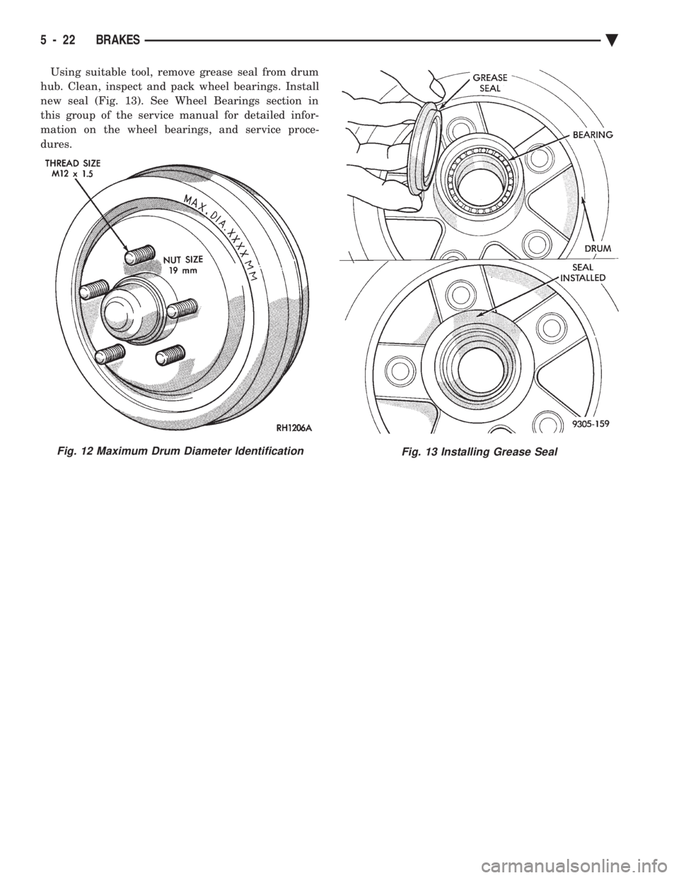
Using suitable tool, remove grease seal from drum
hub. Clean, inspect and pack wheel bearings. Install
new seal (Fig. 13). See Wheel Bearings section in
this group of the service manual for detailed infor-
mation on the wheel bearings, and service proce-
dures.
Fig. 12 Maximum Drum Diameter IdentificationFig. 13 Installing Grease Seal
5 - 22 BRAKES Ä
Page 173 of 2438
WHEEL CYLINDERS INDEX
page page
General Information ....................... 23
Installing Wheel Cylinders .................. 24 Service Procedures
....................... 23
GENERAL INFORMATION
The piston boots are of the push-on type and pre-
vent moisture from entering the wheel cylinder. To perform service operations or inspections of the
rear wheel brake cylinders. It will be necessary to re-
move the cylinders from the support plate and disas-
semble on the bench.
CAUTION: Wheel cylinders with cup expanders
must have cup expanders after any service proce-
dures (reconditioning or replacement).
SERVICE PROCEDURES
REMOVING WHEEL CYLINDERS FROM BRAKE SUPPORT PLATES
With brake drums removed, inspect the wheel cyl-
inder boots for evidence of a brake fluid leak. Then
block the brake pedal in the stroke position, and vi-
sually check the boots for cuts, tears, or heat cracks.
If any of these conditions exist, the wheel cylinders
should be completely cleaned, inspected and new
parts installed. (A slight amount of fluid on the boot
may not be a leak, but may be preservative fluid
used at assembly.) (1) In case of a leak, remove brake shoes, (replace
if soaked with grease or brake fluid.) (2) Thoroughly clean area of wheel cylinder, where
hydraulic brake line connects to wheel cylinder. Dis-
connect hydraulic brake tube from wheel cylinder
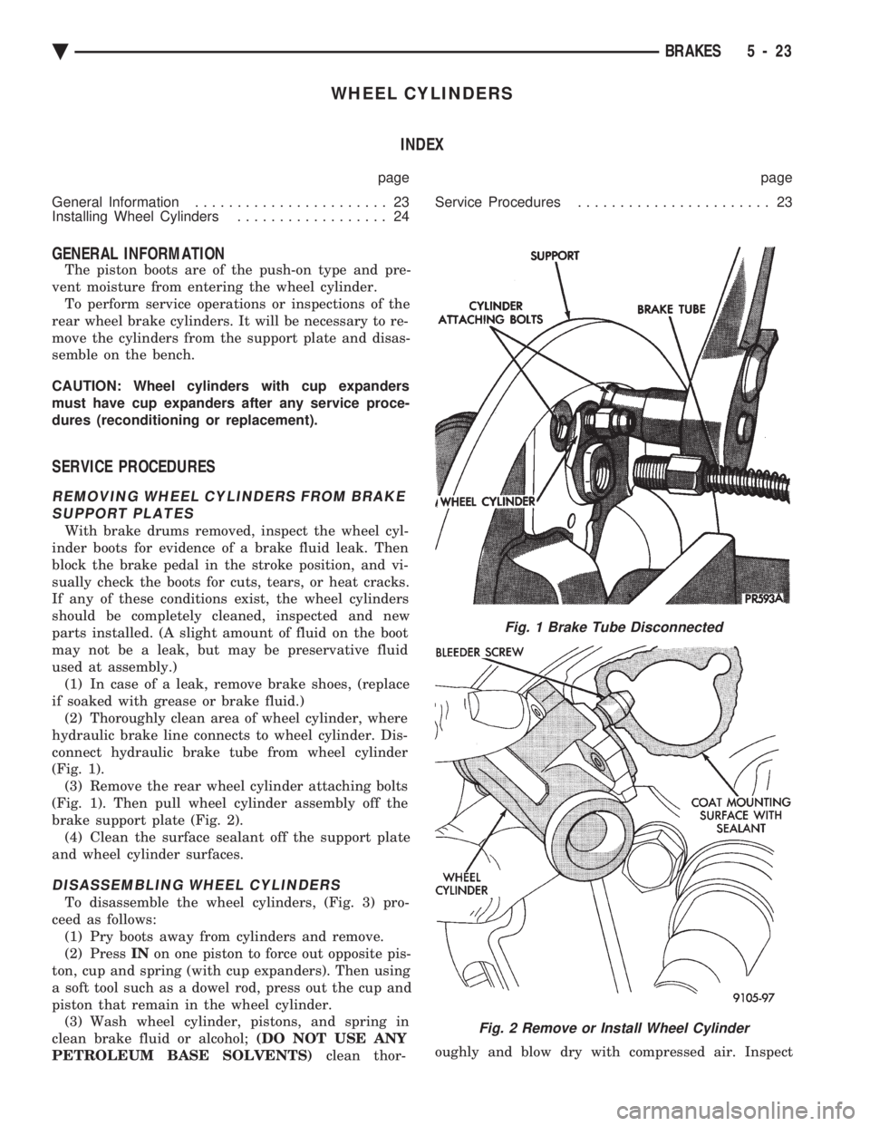
(Fig. 1). (3) Remove the rear wheel cylinder attaching bolts
(Fig. 1). Then pull wheel cylinder assembly off the
brake support plate (Fig. 2). (4) Clean the surface sealant off the support plate
and wheel cylinder surfaces.
DISASSEMBLING WHEEL CYLINDERS
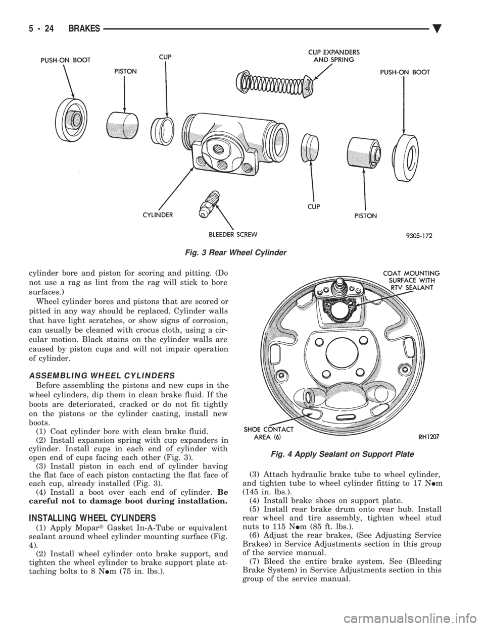
To disassemble the wheel cylinders, (Fig. 3) pro-
ceed as follows: (1) Pry boots away from cylinders and remove.
(2) Press INon one piston to force out opposite pis-
ton, cup and spring (with cup expanders). Then using
a soft tool such as a dowel rod, press out the cup and
piston that remain in the wheel cylinder. (3) Wash wheel cylinder, pistons, and spring in
clean brake fluid or alcohol; (DO NOT USE ANY
PETROLEUM BASE SOLVENTS) clean thor- oughly and blow dry with compressed air. Inspect
Fig. 1 Brake Tube Disconnected
Fig. 2 Remove or Install Wheel Cylinder
Ä
BRAKES 5 - 23
Page 174 of 2438
cylinder bore and piston for scoring and pitting. (Do
not use a rag as lint from the rag will stick to bore
surfaces.) Wheel cylinder bores and pistons that are scored or
pitted in any way should be replaced. Cylinder walls
that have light scratches, or show signs of corrosion,
can usually be cleaned with crocus cloth, using a cir-
cular motion. Black stains on the cylinder walls are
caused by piston cups and will not impair operation
of cylinder.
ASSEMBLING WHEEL CYLINDERS
Before assembling the pistons and new cups in the
wheel cylinders, dip them in clean brake fluid. If the
boots are deteriorated, cracked or do not fit tightly
on the pistons or the cylinder casting, install new
boots. (1) Coat cylinder bore with clean brake fluid.
(2) Install expansion spring with cup expanders in
cylinder. Install cups in each end of cylinder with
open end of cups facing each other (Fig. 3). (3) Install piston in each end of cylinder having
the flat face of each piston contacting the flat face of
each cup, already installed (Fig. 3). (4) Install a boot over each end of cylinder. Be
careful not to damage boot during installation.
INSTALLING WHEEL CYLINDERS
(1) Apply Mopar tGasket In-A-Tube or equivalent
sealant around wheel cylinder mounting surface (Fig.
4). (2) Install wheel cylinder onto brake support, and
tighten the wheel cylinder to brake support plate at-
taching bolts to 8 N Im (75 in. lbs.). (3) Attach hydraulic brake tube to wheel cylinder,
and tighten tube to wheel cylinder fitting to 17 N Im
(145 in. lbs.). (4) Install brake shoes on support plate.
(5) Install rear brake drum onto rear hub. Install
rear wheel and tire assembly, tighten wheel stud
nuts to 115 N Im (85 ft. lbs.).
(6) Adjust the rear brakes, (See Adjusting Service
Brakes) in Service Adjustments section in this group
of the service manual. (7) Bleed the entire brake system. See (Bleeding
Brake System) in Service Adjustments section in this
group of the service manual.
Fig. 3 Rear Wheel Cylinder
Fig. 4 Apply Sealant on Support Plate
5 - 24 BRAKES Ä
Page 175 of 2438
BRAKE SUPPORT ASSEMBLY
REMOVAL
Back off parking brake adjusting nut to provide
slack in cable. With wheel and brake drum removed, disconnect
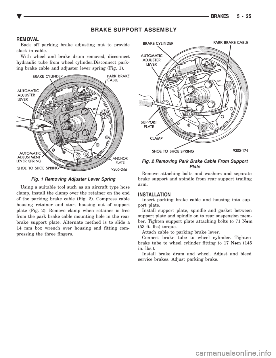
hydraulic tube from wheel cylinder.Disconnect park-
ing brake cable and adjuster lever spring (Fig. 1).
Using a suitable tool such as an aircraft type hose
clamp, install the clamp over the retainer on the end
of the parking brake cable (Fig. 2). Compress cable
housing retainer and start housing out of support
plate (Fig. 2). Remove clamp when retainer is free
from the park brake cable mounting hole in the rear
brake support plate. Alternate method is to slide a
14 mm box wrench over housing end fitting com-
pressing the three fingers. Remove attaching bolts and washers and separate
brake support and spindle from rear support trailing
arm.
INSTALLATION
Insert parking brake cable and housing into sup-
port plate. Install support plate, spindle and gasket between
support plate and spindle on to rear suspension mem-
ber. Tighten support plate attaching bolts to 71 N Im
(53 ft. lbs) torque. Attach cable to parking brake lever.
Connect brake tube to wheel cylinder. Tighten
brake tube to wheel cylinder fitting to 17 N Im (145
in. lbs.). Install brake drum and wheel. Adjust and bleed
service brakes. Adjust parking brake.
Fig. 1 Removing Adjuster Lever Spring
Fig. 2 Removing Park Brake Cable From Support Plate
Ä BRAKES 5 - 25