Page 326 of 2438

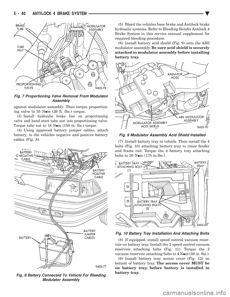
against modulator assembly. Then torque proportion-
ing valve to 35 N Im (26 ft. lbs.) torque.
(3) Install hydraulic brake line on proportioning
valve and hand start tube nut into proportioning valve.
Torque tube nut to 18 N Im (159 in. lbs.) torque.
(4) Using approved battery jumper cables, attach
battery, to the vehicles negative and positive battery
cables (Fig. 8). (5) Bleed the vehicles base brake and Antilock brake
hydraulic systems. Refer to Bleeding Bendix Antilock 4
Brake System in this service manual supplement for
required bleeding procedure. (6) Install battery acid shield (Fig. 9) onto the ABS
modulator assembly. Be sure acid shield is securely
attached to modulator assembly before installing
battery tray.
(7) Install battery tray in vehicle. Then install the 4
bolts (Fig. 10) attaching battery tray to inner fender
and frame rail. Torque the 4 battery tray attaching
bolts to 20 N Im (175 in.lbs.).
(8) If equipped, install speed control vacuum reser-
voir on battery tray. Install the 2 speed control vacuum
reservoir attaching bolts (Fig. 11). Torque the 2
vacuum reservoir attaching bolts to 4 N Im (30 in. lbs.).
(9) Install battery tray access cover (Fig. 12) on
bottom of battery tray. The access cover MUST be
on battery tray, before battery is installed in
battery tray.
Fig. 8 Battery Connected To Vehicle For Bleeding Modulator Assembly
Fig. 7 Proportioning Valve Removal From Modulator Assembly
Fig. 9 Modulator Assembly Acid Shield Installed
Fig. 10 Battery Tray Installation And Attaching Bolts
5 - 40 ANTILOCK 4 BRAKE SYSTEM Ä
Page 328 of 2438

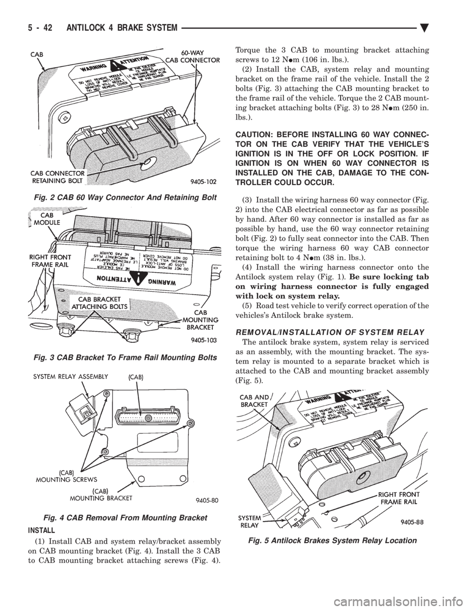
INSTALL (1) Install CAB and system relay/bracket assembly
on CAB mounting bracket (Fig. 4). Install the 3 CAB
to CAB mounting bracket attaching screws (Fig. 4). Torque the 3 CAB to mounting bracket attaching
screws to 12 N Im (106 in. lbs.).
(2) Install the CAB, system relay and mounting
bracket on the frame rail of the vehicle. Install the 2
bolts (Fig. 3) attaching the CAB mounting bracket to
the frame rail of the vehicle. Torque the 2 CAB mount-
ing bracket attaching bolts (Fig. 3) to 28 N Im (250 in.
lbs.).
CAUTION: BEFORE INSTALLING 60 WAY CONNEC-
TOR ON THE CAB VERIFY THAT THE VEHICLE'S
IGNITION IS IN THE OFF OR LOCK POSITION. IF
IGNITION IS ON WHEN 60 WAY CONNECTOR IS
INSTALLED ON THE CAB, DAMAGE TO THE CON-
TROLLER COULD OCCUR.
(3) Install the wiring harness 60 way connector (Fig.
2) into the CAB electrical connector as far as possible
by hand. After 60 way connector is installed as far as
possible by hand, use the 60 way connector retaining
bolt (Fig. 2) to fully seat connector into the CAB. Then
torque the wiring harness 60 way CAB connector
retaining bolt to 4 N Im (38 in. lbs.).
(4) Install the wiring harness connector onto the
Antilock system relay (Fig. 1). Be sure locking tab
on wiring harness connector is fully engaged
with lock on system relay. (5) Road test vehicle to verify correct operation of the
vehicles's Antilock brake system.
REMOVAL/INSTALLATION OF SYSTEM RELAY
The antilock brake system, system relay is serviced
as an assembly, with the mounting bracket. The sys-
tem relay is mounted to a separate bracket which is
attached to the CAB and mounting bracket assembly
(Fig. 5).
Fig. 2 CAB 60 Way Connector And Retaining Bolt
Fig. 3 CAB Bracket To Frame Rail Mounting Bolts
Fig. 4 CAB Removal From Mounting Bracket
Fig. 5 Antilock Brakes System Relay Location
5 - 42 ANTILOCK 4 BRAKE SYSTEM Ä
Page 333 of 2438

MANUAL TRANSAXLE CLUTCH
CONTENTS
page page
CLEANING PRECAUTIONS ................. 6
CLUTCH CABLE MECHANISM .............. 1
CLUTCH CABLE REPLACEMENT ............ 2
CLUTCH CHATTER COMPLAINTS ........... 1
CLUTCH DISC REPLACEMENT ............. 5
CLUTCH PEDAL NOISE/POP ............... 2 CLUTCH PEDAL POSITION SWITCH
......... 4
EXCESSIVE CLUTCH SPIN TIME/CLASH INTO REVERSE COMPLAINTS ............ 1
GENERAL INFORMATION .................. 1
RELEASE BEARING AND FORK ............. 6
GENERAL INFORMATION
Throughout this group, references may be made to
a particular vehicle by letter or number designation.
A chart showing the breakdown of these designations
is included in the Introduction Section at the front of
this service manual. The clutch used in all models are a single, dry disc
type with no adjustment for wear being provided in
the clutch itself. The clutch pedal is connected to the release shaft
through a cable and lever. The upper end of the clutch pedal pivots in the
pedal bracket on two nylon bushings. These bushings
do not require periodic lubrication.
CLUTCH CHATTER COMPLAINTS
For all clutch chatter complaints, do the following:
(1) Check for loose, misaligned, or broken engine
and transmission mounts. If present, they should be
corrected at this time. Test vehicle for chatter. If
chatter is gone, there is no need to go any further. If
chatter persists: (2) Check to see if clutch cable routing is correct
and operates smoothly. (3) Check for loose connections in drive train. Cor-
rect any problems and determine if clutch chatter
complaints has been satisfied. If not, (4) Remove transaxle. See Group 21, Manual Tran-
saxle, for procedure. (5) Check to see if the release bearing is sticky or
binding. Replace bearing, if needed. (6) Check linkage for excessive wear on bushings.
Replace all worn parts. A small amount of bearing
grease between the release shaft bushings and the
shaft is beneficial, but not required. (7) Check flywheel and clutch pressure plate for
contamination (dirt, oil) or scored. Replace flywheel
and/or pressure plate, if required. (8) Check to see if the clutch disc hub splines are
damaged. Replace with new disc. (9) Check input shaft splines for damage. Replace
if necessary. (10) Check for uneven wear on clutch fingers.
EXCESSIVE CLUTCH SPIN TIME/CLASH INTO
REVERSE COMPLAINTS
For all excessive clutch spin time/clash into reverse
complaints, do the following: (1) Depress clutch pedal to floor and hold. After
three seconds, shift to reverse. If clash is present,
clutch has excessive spin time. (2) Remove transaxle. See Group 21, Manual Tran-
saxle, for procedure. (3) Check the input shaft spline, clutch disc splines
and release bearing for dry rust. If present, clean
rust off and apply a light coat of bearing grease to
the input shaft splines. Apply grease on the input
shaft splines only where the clutch disc slides. (4) Check to see if the clutch disc hub splines are
damaged, replace with new disc if required. (5) Check the input shaft for damaged splines. Re-
place as necessary. (6) Check for excessive clutch disc runout or
warpage. (7) Install clutch assembly and transaxle.
CLUTCH CABLE MECHANISM
The manual transaxle clutch release system has a
unique self-adjusting mechanism to compensate for
clutch disc wear. This adjuster mechanism is located
within the clutch pedal. The preload spring main-
tains tension on the cable. This tension keeps the
clutch release bearing continuously loaded against
the fingers of the clutch cover assembly. When the pedal is depressed, teeth on the adjuster
and the positioner engage and pull the release cable.
A spring located behind the adjuster ensures proper
tooth engagement. When the pedal is released, the adjuster contacts
the bumper. This separates the adjuster and posi-
tioner teeth, allowing the preload spring to function.
Ä MANUAL TRANSAXLE CLUTCH 6 - 1
Page 339 of 2438
hicle is steam cleaned. The facing of the disc will
absorb moisture. The force exerted by the pressure
plate will bond the facings to flywheel and/or, pres-
sure plate, if vehicle is allowed to stand for some
time before use. If this condition occurs, it will re- quire replacement of disc assembly, flywheel, and/or
clutch assembly. After cleaning, drive the vehicle to
its normal clutch operating temperature. This will
dry off disc assembly, pressure plate, and flywheel.
SERVICE DIAGNOSISÐCLUTCH GRAB/CHATTER
Ä MANUAL TRANSAXLE CLUTCH 6 - 7
Page 340 of 2438
SERVICE DIAGNOSISÐCLUTCH SLIPS
6 - 8 MANUAL TRANSAXLE CLUTCH Ä
Page 341 of 2438
SERVICE DIAGNOSISÐIMPROPER CLUTCH RELEASE
Ä MANUAL TRANSAXLE CLUTCH 6 - 9
Page 342 of 2438
SERVICE DIAGNOSISÐCLUTCH NOISE
6 - 10 MANUAL TRANSAXLE CLUTCH Ä
Page 343 of 2438

COOLING SYSTEM
CONTENTS
page page
ACCESSORY DRIVE BELTS ............... 24
ENGINE BLOCK HEATER ................. 28
GENERAL INFORMATION .................. 1 SERVICE PROCEDURES
.................. 10
SPECIFICATIONS ....................... 29
GENERAL INFORMATION
Throughout this group, references may be made to
a particular vehicle by letter or number designation.
A chart showing the breakdown of these designations
is included in the Introduction Section at the front of
this service manual.
COOLING SYSTEM
The cooling system consists of an engine cooling
module, thermostat, coolant, a water pump to circu-
late the coolant. The engine cooling module may con-
sist of a radiator, electric fan motor, shroud, radiator
pressure cap, coolant reserve system, transmission oil
cooler, hoses, clamps, air condition condenser, trans-
mission oil lines and charge air cooler.
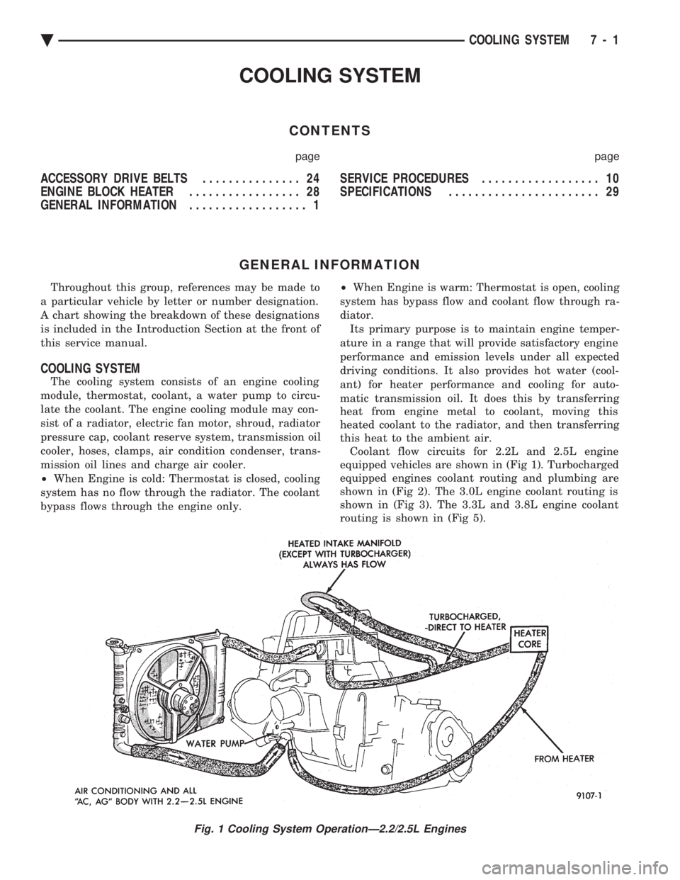
² When Engine is cold: Thermostat is closed, cooling
system has no flow through the radiator. The coolant
bypass flows through the engine only. ²
When Engine is warm: Thermostat is open, cooling
system has bypass flow and coolant flow through ra-
diator. Its primary purpose is to maintain engine temper-
ature in a range that will provide satisfactory engine
performance and emission levels under all expected
driving conditions. It also provides hot water (cool-
ant) for heater performance and cooling for auto-
matic transmission oil. It does this by transferring
heat from engine metal to coolant, moving this
heated coolant to the radiator, and then transferring
this heat to the ambient air. Coolant flow circuits for 2.2L and 2.5L engine
equipped vehicles are shown in (Fig 1). Turbocharged
equipped engines coolant routing and plumbing are
shown in (Fig 2). The 3.0L engine coolant routing is
shown in (Fig 3). The 3.3L and 3.8L engine coolant
routing is shown in (Fig 5).
Fig. 1 Cooling System OperationÐ2.2/2.5L Engines
Ä COOLING SYSTEM 7 - 1