Page 968 of 1164

TROUBLESHOOTING GUIDE
Symptom: Condenser fan and magnetic clutch do not operate.
03uoux-023
r
3EAR WIPER 10A OA
L
03uoux-02.
I
1 Step 1 Check fuses
1. Check the following fuses.
Fuse Amperage Location
AD FAN 20A In main fuse box
REAR WIPER 10A In fuse box
2. If the fuse is burned, check for a short-circuit in the wiring
harness before replacing it.
3. If the fuses are OK, go to Step 2.
I
23uoux-011
Step 2 Measure voltage at A/C relay connector
1. Run the engine at idle.
2. Turn the A/C and blower switches ON.
3. Measure the voltage at the following terminal wires of the
A/C relay connector. VEX Battery voltage
,
Wire
0-Q
W) Voltage Action
VB Next check wire (L/Y)
ov Repair wire (L/G)
V0 Next check wire (B/L)
ov
VB
ov
VB
ov Repair wire (L/Y)
Repair wire (B/L)
Next check wire (LIB)
Go to Step 3
Replace A/C relay
Step 3 Measure voltage at A/C switch
Measure the voltage at the following terminal wires of the A/C
switch connectors.
VB: Battery voltage
Step 4 Measure voltage at thermoswitch
Measure the voltage at the terminal wires of the thermoswitch
connector.
VB: Battery voltage
Wire
(G/R)
WB)
Voltage
VB
ov
VB
OV
Action
Repair wire (G/R)
Next check wire (G/B)
Go to Step 5
Check ECU ooeration
1 -. [ Refer to Secti6n F
u-12
Page 981 of 1164
HEATER U
23UOUX-01
23uoux-02
Inspection
Blower motor
1, Remove the glove box. (Refer to Section S.)
2. Disconnect the blower motor connectors.
3. Verify that the blower motor runs when connecting battery
voltage to terminal a and grounding terminal b.
4. If not as specified, replace the blower motor.
Resistor assembly
1. Remove the glove box. (Refer to Section S.)
2. Disconnect the resistor assembly connectors.
3. Check continuity between terminals.
G-O: Indicates continuity
4. If not as specified, replace the resistor assembly.
u-25
Page 982 of 1164
U HEATER
HEATER CONTROL UNIT
Removal / Installation
1. Disconnect the negative battery cable.
2. Remove in the order shown in the figure.
3. Install in the reverse order of removal.
Note
l After installing the Mix, Mode, and Ret-Fresh wires. verifv that each lever moves its full stroke.
1. Side panel
2. Lower panel (R.H.)
3. Lower panel (Center)
4. Meter hood 5. Glove box
6. Glove box cover
7. Mode wire
8. Mix wire
9. Ret-Fresh wire
IO. Heater control assembly
U-26
Page 1012 of 1164
AIR CONDITIONER
23UOUX-051
23UOUX-05
23UOUX-05
U-56
Caution
l While testing refrigerant pressure switch No.2, care-
fully note the high-pressure side refrigerant pres-
sure. If the pressure increases above 1,766 kPa (18
kg/cm2, 256 psi), stop the testing. _,
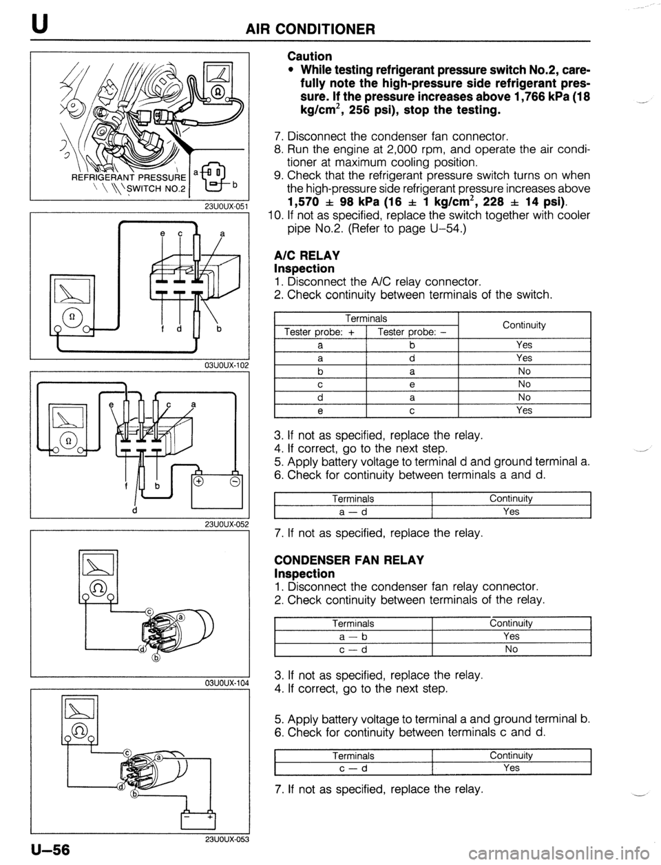
7. Disconnect the condenser fan connector.
8. Run the engine at 2,000 rpm, and operate the air condi-
tioner at maximum cooling position.
9. Check that the refrigerant pressure switch turns on when
the high-pressure side refrigerant pressure increases above
1,570 f 98 kPa (16 f 1 kg/cm2, 228 f 14 psi).
IO. If not as specified, replace the switch together with cooler
pipe No.2. (Refer to page U-54.)
A/C RELAY
Inspection
1. Disconnect the A/C relay connector.
2. Check continuity between terminals of the switch.
Terminals
Tester probe: + 1 Tester probe: -
a b Continuity
Yes
3. If not as specified, replace the relay.
4. If correct, go to the next step.
5. Apply battery voltage to terminal d and ground terminal a.
6. Check for continuity between terminals a and d.
Terminals
a-d Continuity
Yes
7. If not as specified, replace the relay.
CONDENSER FAN RELAY
Inspection
1. Disconnect the condenser fan relay connector.
2. Check continuity between terminals of the relay.
Terminals Continuity
I a-b Yes I
2
I c-d I No I
A 3. If not as specified, replace the relay.
4. If correct, go to the next step.
5. Apply battery voltage to terminal a and ground terminal b.
6. Check for continuity between terminals c and d.
Terminals Continuity
c-d Yes
7. If not as specified, replace the relay.
Page 1013 of 1164
AIR CONDITIONER U
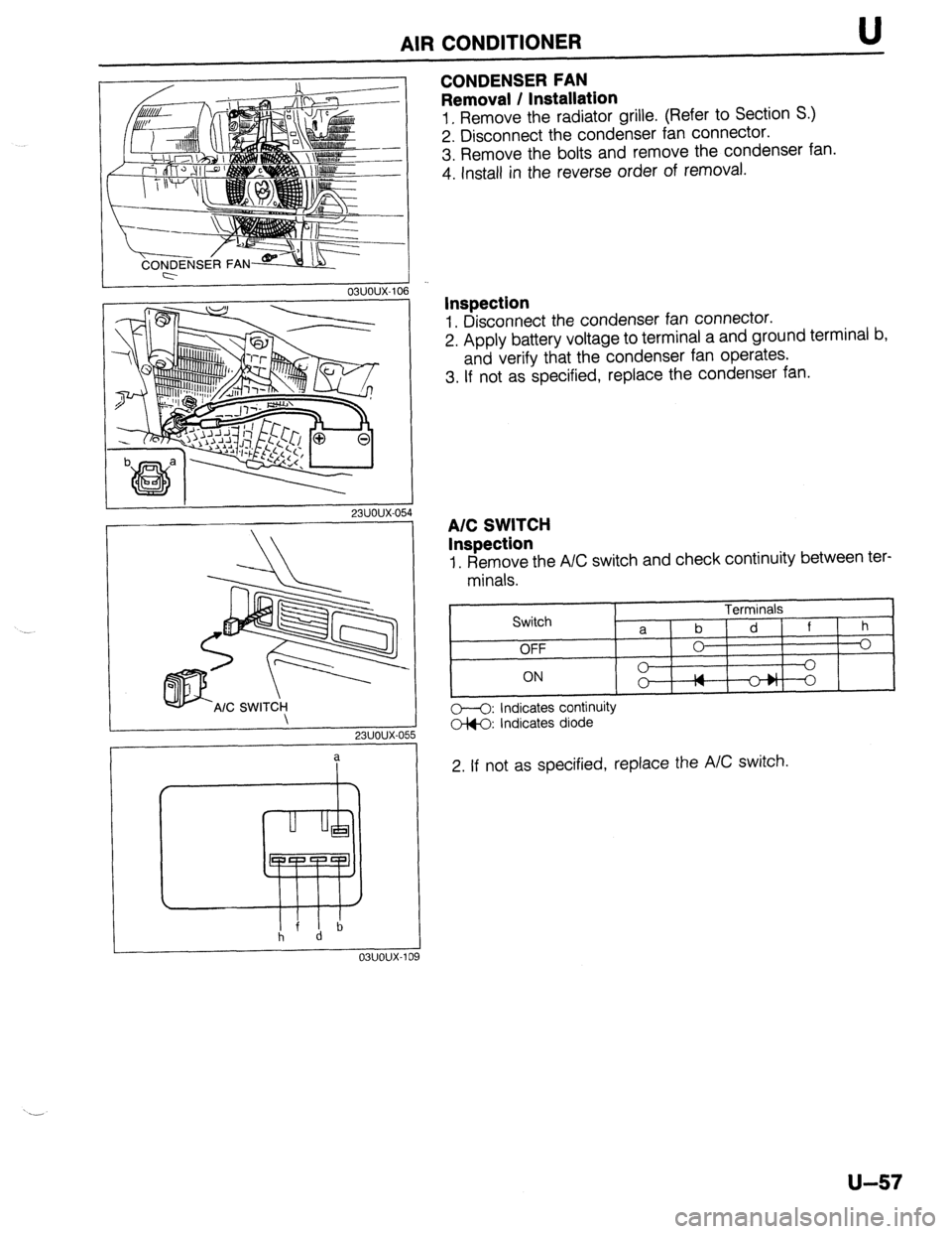
CONDENSER FAN
Removal / Installation
1. Remove the radiator grille. (Refer to Section S.)
2. Disconnect the condenser fan connector.
3. Remove the bolts and remove the condenser fan.
4. Install in the reverse order of removal.
I 03uoux-106
I
23UOUX-05
I
r 23UOUX-OE
a
19
Inspection
1. Disconnect the condenser fan connector.
2. Apply battery voltage to terminal a and ground terminal b,
and verify that the condenser fan operates.
3. If not as specified, replace the condenser fan.
A/C SWITCH
Inspection
1. Remove the A/C switch and check continuity between ter-
minals.
0-O: Indicates continuity
G-k0 Indicates diode
2. If not as specified, replace the A/C switch.
u-57
Page 1049 of 1164
PARTS INDEX
‘I
A
ACCELERATOR CABLE ............................. F-l 14
ACCELERATOR PEDAL ............................. F-l 14
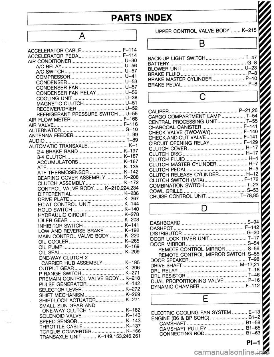
AIR CONDITIONER ...................................... u-30
A/C RELAY.. ........................................... U-56
A/C SWITCH ...........................................
U-57
COMPRESSOR.. ..................................... U-41
CONDENSER.. ....................................... U-53
CONDENSER FAN ................................. u-57
CONDENSER FAN RELAY .................... U-56
COOLING UNIT ..................................... U-38
MAGNETIC CLUTCH ............................. u-51
RECEIVER/DRIER .................................. U-52
REFRIGERANT PRESSURE SWITCH.. .. U-55
AIR FLOW METER ..................................... F-l 68
AIR VALVE.. ................................................ F-l 16
ALTERNATOR .............................................. G-10
ANTENNA FEEDER
AUDIO
....... .......................................................................................... T-i;
AUTOMATIC TRANSAXLE ............................. K-l
2-4 BRAKE BAND ................................ K-l 97
3-4 CLUTCH.. ....................................... K-l 87
ACCUMULATORS ................................ K-l 67
ATF ....................................................... K-135
ATF THERMOSENSOR ........................ K-142
BEARING COVER ASSEMBLY ............ K-208
CLUTCH ASSEMBLY ........................... K-l 72
CONTROL VALVE BODY.. .....
K-21 0,224,234
DIFFERENTIAL ..................................... K-236
DRIVE PLATE.. ..................................... K-267
EC-AT CONTROL UNIT ....................... K-144
HOLD SWITCH ..................................... K-140
HYDRAULIC CIRCUIT .......................... K-278
IDLER GEAR ........................................ K-203
INHIBITOR SWITCH ............................. K-l 41
LOW AND REVERSE BRAKE .............. K-192
MAIN CONTROL VALVE BODY .......... K-220
OIL COOLER.. ...................................... K-265
OIL PUMP ............................................
K-169
OIL SEAL ..............................................
K-209
ONE-WAY CLUTCH 2
CARRIER HUB ASSEMBLY ............... K-185
OUTPUT GEAR .................................... K-206
P RANGE SWITCH.. ............................. K-271
PREMAIN CONTROL VALVE BODY .a. K-218
PULSE GENERATOR ........................... K-142
SELECTOR LEVER ............................... K-272
SHIFT MECHANISM ............................. K-269
SHIFT-LOCK ACTUATOR
..................... K-271
SMALL SUN GEAR AND
ONE-WAY CLUTCH 1 ........................ K-l 82
SOLENOID VALVE.. ............................. K-l 43
SPEEDSENSOR .................................. K-l 43
THROTTLE CABLE .............................. K-l 37
TORQlJE CONVERTER.. ...................... K-l 66
TRANSAXLE UNIT. ......... K-149,153,246,261 UPPER CONTROL VALVE BODY.. ..... K-215
BACK-UP LIGHT SWITCH..
..........................
BATTERY T;4;
- .......................................................
BLOWER UNIT ............................................
U-23
BRAKE FLUID.. .............................................. P-8
BRAKE MASTER CYLINDER. ...................... P-10
BRAKE PEDAL ...............................................
P-8
C
CALIPER .................................................. P-21,26
CARGO COMPARTMENT LAMP ................. T-54
CENTRAL PROCESSING UNIT..
.................. T-55
CHARCOAL CANISTER ............................. F-l 41
CHECK VALVE (TWO-WAY) .......................
CHECK-AND-CUT VALVE - .......................... ;-;b$
CIRCUIT OPENING RELAY.. ...................... F-129
CLUTCH COVER ......................................... H-l 7
CLUTCH DISC ............................................. H-l 7
CLUTCH FLUID ............................................. H-4
CLUTCH MASTER CYLINDER.. .................... H-7
CLUTCH PEDAL ............................................ H-5
CLUTCH RELEASE CYLINDER..
................. H-12
CLUTCH SWITCH (MTX) ............................ F-l 72
COMBINATION SWITCH .............................. T-23
COWL GRILLE ............................................. S-53
CRUISE CONTROL UNIT.. ...................... T-78,85
D
DASHBOARD ............................................... S-94
DASHPOT ................................................... F-l 42
DISTRIBUTOR .............................................. G-20
DOOR LOCK TIMER UNIT ........................... T-17
DOOR MIRROR ............................................ S-54
REMOTE CONTROL MIRROR ............... S-56
REMOTE CONTROL MIRROR SWITCH. S-55
DOOR SPEAKER .......................................... T-98
DRIVE SHAFT.. ....................................... M-l 7,21
DRL RELAY.. ................................................ T-18
DRL RESISTOR ............................................ T-46
DUAL PROPORTIONING VALVE..
............... P-l 6
DYNAMIC CHAMBER ................................ F-l 12
E
ELECTRIC COOLING FAN SYSTEM ........... E-13
ENGINE (B6 & BP SOHC) ........................... Bl-2
CAMSHAFT ..........................................
Bl-58
CAMSHAFT PULLEY ...........................
Bl-65
CONNECTING ROD ............................. 81-63
PI-I
Page 1058 of 1164
Z-Gl-2 Contents of and Using Electrical Wiring Diagrams
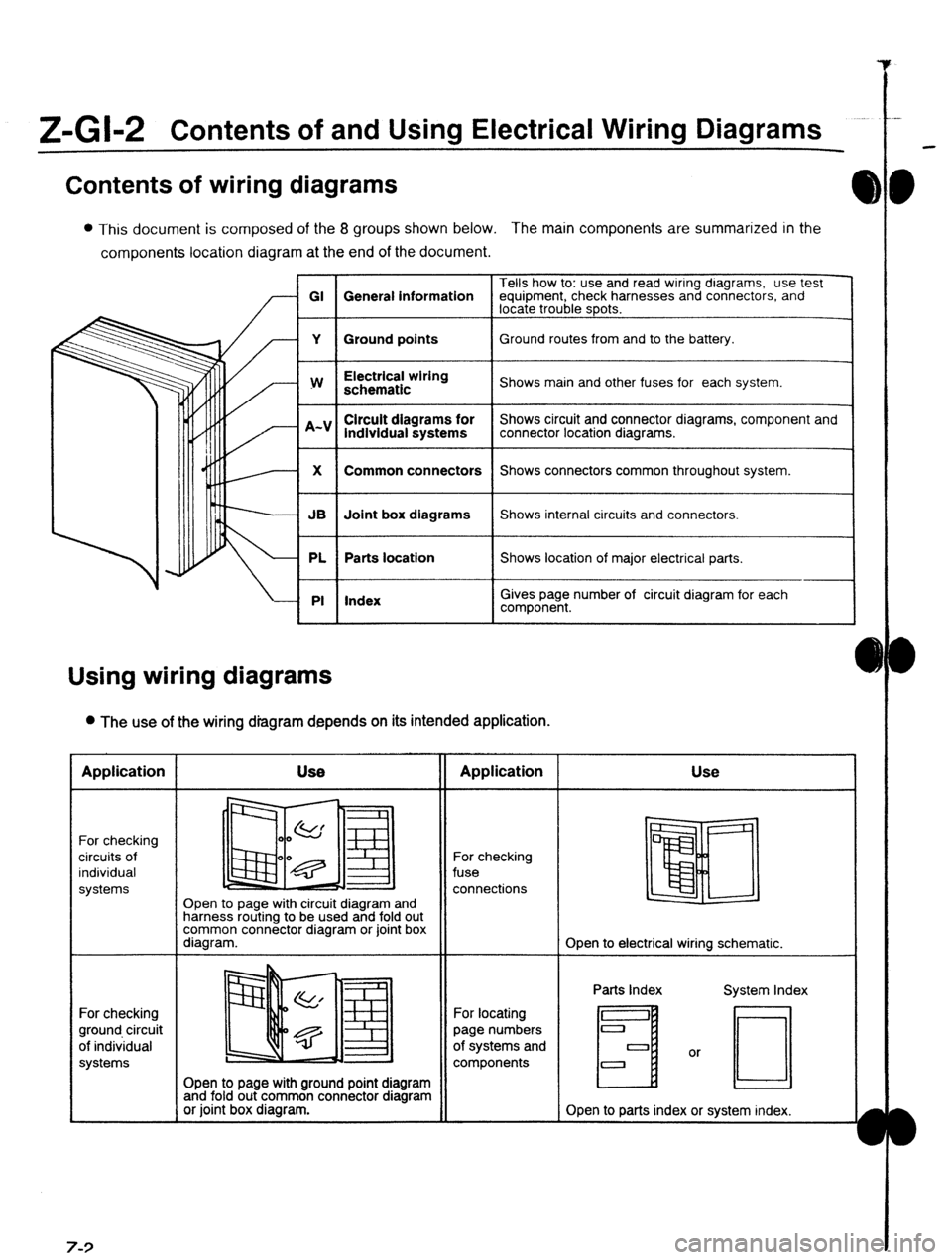
Contents of wiring diagrams
l This document is composed of the 8 groups shown below. The main components are summarized in the
components location diagram at the end of the document.
Tells how to: use and read wiring dragrams, use test
GI General information equipment, check harnesses and connectors, and
locate trouble spots.
Y Ground points Ground routes from and to the battery.
I
w
I Electrical wiring
schematic
I Shows main and other fuses for each system.
lndlvidual systems
I Shows circuit and connector diagrams, component and
connector location diagrams.
1
X
I Common connectors
I Shows connectors common throughout system.
I
JB Joint box diagrams Shows internal circuits and connectors.
PL Parts location Shows location of major electrical parts.
PI Index
I
I
Gives page number of circuit diagram for each
component.
Using wiring diagrams
l The use of the wiring diagram depends on its intended application. Application
For checking
circuits of
individual
systems
For checking
ground circuit
of individual
systems 7-3 Use
II Application
Open to page with circuit diagram and
harness routing to be used and fold out
common connector diagram or joint box
diagram. For checking
fuse
connections Use
Open to electrical wiring schematic.
Open to page with ground point diagram
and fold out common connector diagram
or joint box diagram. For locating
page numbers
of systems and
components Parts Index
H
Open to parts index or system index.
Page 1064 of 1164
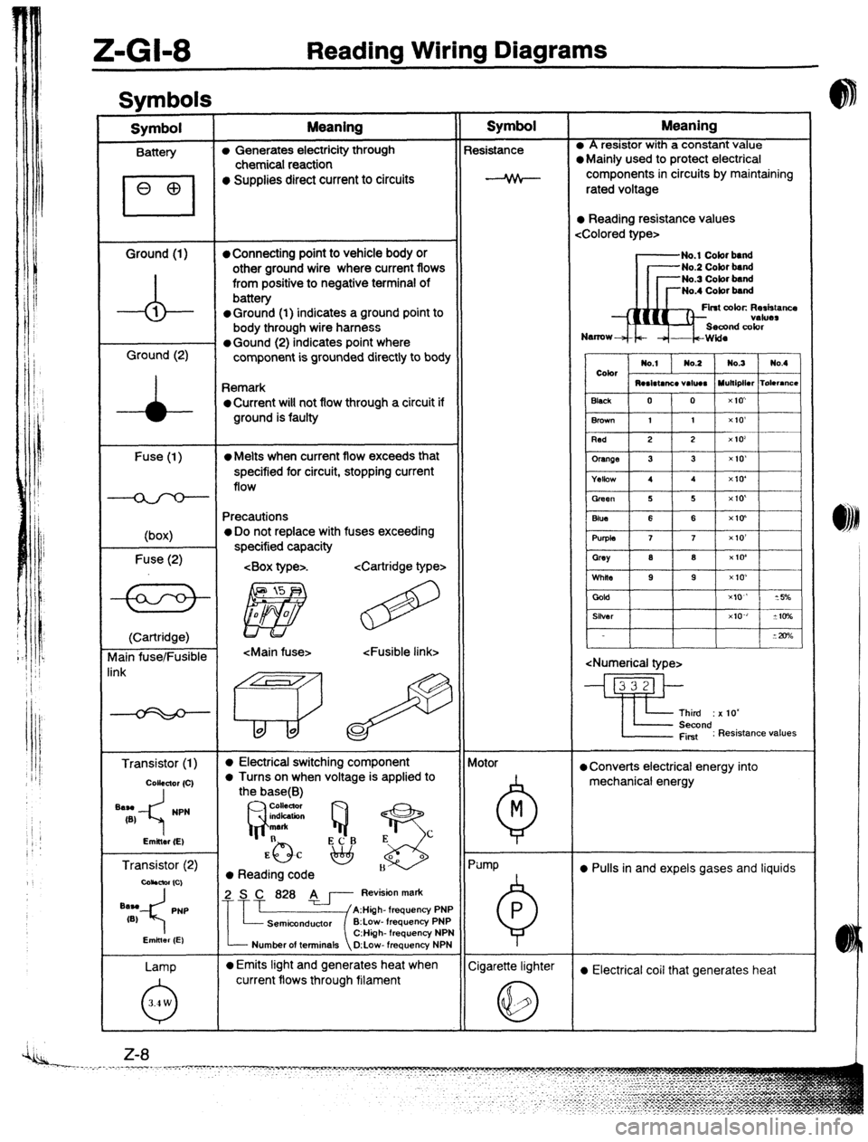
Z-Gl-8 Reading Wiring Diagrams
Svmbols I
Symbol Meaning Symbol Meaning
Battery (I, Generates electricity through Resistance l A resistor with a constant value
chemical reaction l Mainly used to protect electrical
l Supplies direct current to circuits components in circuits by maintaining
rated voltage
l Reading resistance values
Ground (1)
l Connecting point to vehicle body or No.1 Cobr band
-A- other ground wire where current flows -No.2 Cobr band
from positive to negative terminal of -No.3 Cobr band
battery No.4 Cobr band
1
l Ground (1) indicates a ground point to Flnt color. Rerkrancs
body through wire harness
Ground (2) l Gound (2) indicates point where
component is grounded directly to body
Remark
oCurrent wilt not flow through a circuit if
ground is faulty
Fuse (1)
(box)
Fuse (2)
l Melts when current flow exceeds that
specified for circuit, stopping current
flow
Precautions
o Do not replace with fuses exceeding
specified capacity
.
(Cartridge)
vlain fuse/Fusible
Transistor (1)
l Electrical switching component
a Turns on when voltage is applied to Motor
0 Converts electrical energy into
mechanical energy
Transistor (2)
coiibmr (Cl
l Reading code l Pulls in and expels gases and liquids
Lamp
Number of terminals O:Low- frequency NPN
l Emits light and generates heat when
Cigarette lighter
current flows through filament a Electrical coil that generates heat


