1992 MAZDA PROTEGE ignition
[x] Cancel search: ignitionPage 1069 of 1164
Troubleshooting Z-Gl-13
el
-
Ill
31
-
I1
Jl
:n
r.
7a
ver
le
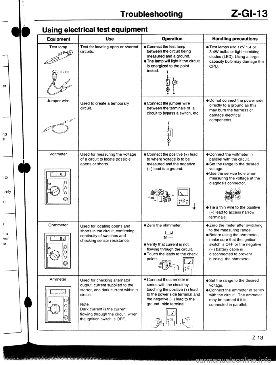
Usina electrical test eaubment -----w - I - Equipment Use Operation Handling precautions
Test lamp Test for locating open or shorted l Connect the test lamp
0 Test lamps use 12V 1.4 or
R circuits. between the circuit being
3.4W bulbs or light- emitting
measured and a ground.
diodes (LED). Using a large
*The
lamp will light if the circuit
capacity bulb may damage the
is energized to the point
CPU.
,.WD,.l
b tested.
Jumper wire
Used to create a temporary l Connect the jumper wire 0 Do not connect the power side
circuit. between the terminals of a directly to a ground as this
circuit to bypass a switch, etc. may burn the harness or
damage electrical
/d<;>‘-
d components.
I
n
Voltmeter
Used for measuring the voltage
l Connect the positive (+) lead l Connect the voltmeter In
of a circuit to locate possible to where voltage is to be parallel with the circuit.
opens or shorts. measured and the negative
0 Set the range to the desired
(- ) lead to a ground. voltage.
l Use the service hole when
measuring the voltage at the
diagnosis connector.
~Tie a thin wire to the posrtive
(+) lead to access narrow
terminals.
Ohmmeter
Ammeter Used for locating opens and
l Zero the ohmmeter. *Zero the meter after switching
shorts in the circuit, confirming
I to the measuring range.
continuity of switches and
checking sensor resistance. &.--
l Before using the ohmmeter,
make sure that the ignition
l Verify that current is not switch is OFF or the negative
flowing through the circuit. (- ) battery cable is
0 Touch the leads to the check disconnected to prevent
points.* burning the ohmmeter.
Used for checking alternator
l Connect the ammeter in l Set the range to the desired
output, current supplied to the series with the circuit by
voltage.
starter, and dark current within a touching the positive (+) lead
l Connect the ammeter in series
circuit. to the power side terminal and
with the circuit. The ammeter
the negative (- ) lead to the
may be burned If it is
Note ground- side terminal.
connected in parallel.
Dark current is the current
flowing through the circuit when
the Ignition switch is OFF.
Page 1070 of 1164
Z-GM 4 Troubleshooting
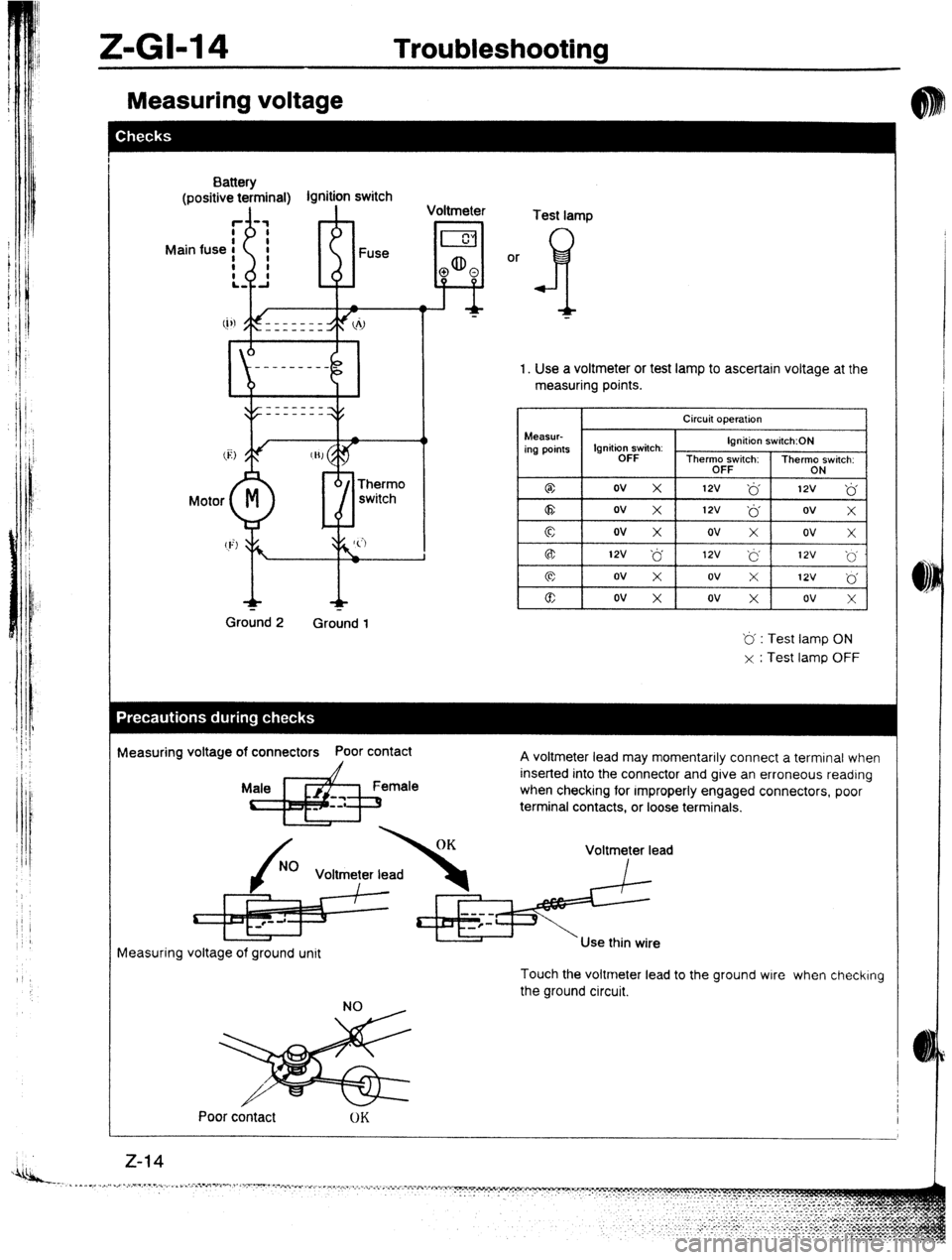
Measuring voltage
, ’
Battery
(positive te;minal) lgnitipn switch
Voltmeter
Fuse
Motor Therm0
switch
+ r-
Ground 2 Ground 1
I
!I4 aD
0 0
Test lamp
or
f
“J-
1. Use a Voltmeter or &St lamp to ascertain voltage at the
measuring points.
Circuit operation
Measur-
ing points Ignitio&Gtch: Ignition switch:ON
Thermo switch: Thermo switch:
OFF ON
@ ov x 12v ‘6 12v
‘6
a ov x 12v ~6 ov
X
c ov x ov x ov X
B: 12v ‘6 12v ‘6 12v ~‘. 0
cc ov x ov X 12v .’ 0
@ ov x ov x ov X
‘b’ : Test lamp ON
x : Test lamp OFF
neasuring voltage of connectors Poor contact
A voltmeter lead may momentarily connect a terminal when
inserted into the connector and give an erroneous reading
when checking for rmproperly engaged connectors, poor
terminal contacts, or loose terminals.
Voltmeter lead
Measuring voltage of ground unit
Touch the voltmeter lead to the ground wire when checking
the ground circuit.
Poor contact
Page 1072 of 1164
II-GM6 Troubleshooting
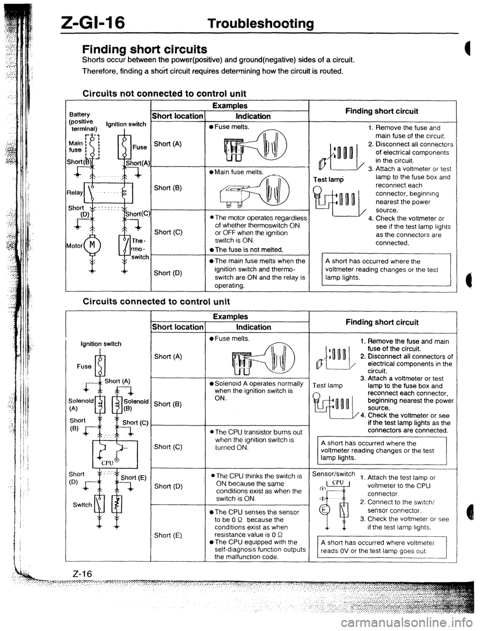
Finding short circuits
Shorts occur between the power(positive) and ground(negative) sides of a circuit.
Therefore, finding a shdit circuit requires determining how the circuit is routed.
Circuits not connected to control unit
Examples
Indication
0 Fuse melts. Finding short circuit
0
Test lamp 1. Remove the fuse and
main fuse of the circurt.
2. Disconnect all connectors
of electrical components
in the circuit.
3. Attach a voltmeter or test
lamp to the fuse box and
reconnect each
connector, beginning
nearest the power
source.
4. Check the voltmeter or
see if the test lamp lights
as the connectors are
connected. Finding short circuit
,,{:““o
1. Remove the fuse and main
fuse of the circuit.
2. Disconnect all connectors of
/ electrical components in the
circuit.
Test lamp 3. Attach a voltmeter or test
lamp to the fuse box and
reconnect each connector,
beginning nearest the power
4. Check the voltmeter or see
if the test lamp lights as the
connectors are connected.
Sensor/switch
1. Attach the test lamp or
voltmeter to the CPU
connector.
2. Connect to the swrtch/
sensor connector.
3. Check the voltmeter or see
if the test lamp lights.
A short has occurred where voltmeter
reads OV or the test lamp goes out,
- Short location
Battery Short (A)
l Main fuse melts.
L* Short(B)
0 The motor operates regardless
of whether thermoswitch ON
or OFF when the ignition
switch is ON. Short (C)
lotor
M
P The-
tmo-
switc *The fuse is not melted.
@The main fuse melts when the
ignition switch and thermo-
switch are ON and the relay is
operating. Short (D)
Circuits connected to control unit
-T Examples
Indication
l Fuse melts.
- Short locatior
I
ignition switch
I
Fuse R-l Short (A)
J+L--l
Short (A) l Solenoid A operates normally
when the ignition switch is
ON.
9enold m rfr solenok
;<
A) u a(B) ’ Short (6)
l The CPU transistor burns out
when the ignition switch is
turned ON. Short (C)
l The CPU thinks the switch is
ON because the same
conditions exist as when the
switch is ON.
*The CPU senses the sensor
to be 0 R because the
conditions exist as when
resistance value is 0 R
*The CPU equipped with the
self-diagnosis function output
the malfunctron code. Short (0)
Swltcl1 ml
Short (E) Z-16
Page 1082 of 1164
kll?lNQ MAQRAY
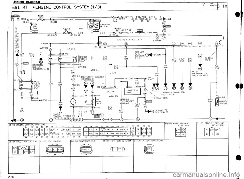
EGI MT l ENGINE CONTROL SYSTEM (l/3)
30A
STARTING
SYSTEM
(SECTION A-
MAIN
RELAY
[FUEL
INJ)
: 1
Ix-181
-W/R [EM) ENGINE CONTRO- UNIT
v (EM) --------+ lc
1G
IB
- LG (EM) 81-01 ~~=~~~===~T-~-~~~---~~--------------------------~--
I I I
FL% A
a
I SHIELD I
WIRE :
/ 1 WATFJ
DIAGNOSIS CONNECTOR
(SECTION u)
!I-01 ENGINE CONTROL UNIT (EM) 81-02 MAIN RELAY iE) 81-03 CIRCUIT OPENING
1” IS 10 ID ,M 1K II IG 1E IC IA 2~ 2~ 2~ 25 20 20 2~ 2K 21 2G 2E 2C 2A (FUEL INJ) RELAY (EM)
)t LG/Y X G/W Y/0 v L/R * L/O Y < x LG/R * x
R/Y B/L B/G L/y R/W (‘;“’ L/B t W/B W/Y W/R x W/L Y/B G/O * R/B R/L LG/W * “;’ * /BP B/O
I” IT 1R IP IN IL lJ 1H IF ID 16 2L 2X 2” 27 2R 2P 2N 2L 2J 2H 2F 20 28
II -04 FUEL TANK UNIT [RI Bl-05 IGNITER (EM) Bl-06 CONDENSER (EM) 81-07 IGNITION COIL (EM) ~1-08 OXYGEN SENSOR (EM)
~~~ (w] (jj (JJD @
Z-26
Page 1083 of 1164
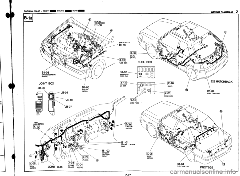
“.w- MIM . FRONT- ENGINE - REAR - - __._ -._.- -.~ -~ ~.. .-_.--_* . . . . . -...-- --
- WIRING DIAGRAM
IGNITION COIL
IA-VI/ FUSE BOX FUSE BOX
Bl-02
MAIN RELAY
(FUEL INJ)
JOINT BOX
I h
(_an&=y “t Ix-16j
I- 323 HATCHBACH
h-s* A,- (WW
JB-06 DI-U3 . dl, u=nE)
I
IGNITER (GRAY) 4b
s/JB-04 B&M
FUEL TANK “NIT
JOINT
CONNECTOR
A - Bl-01
\W\“ A Bl -03 /
JO& BOX
(F)-o /x-o! (BucI() (F)-(EM) w PROTEGii
Z-27
Page 1088 of 1164
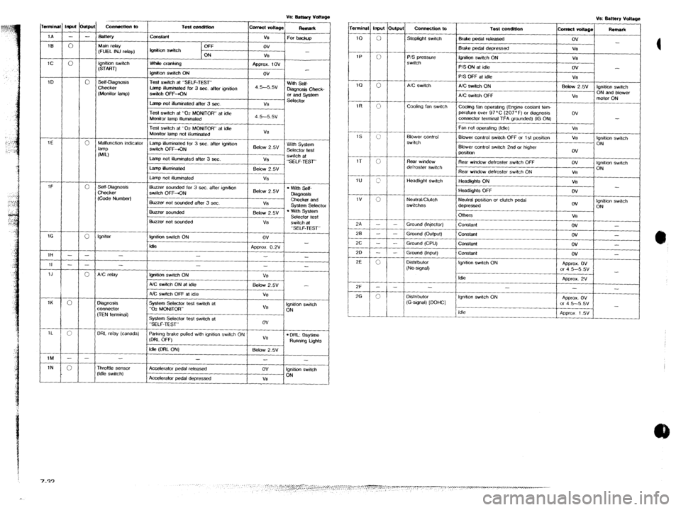
T.&condition
-t
Off
IQ”&” switch
ON
Whik cranking
lgnitlon switch ON
Test switch at “SELF-TEST”
Lamp illuminated for 3 sec. after ignition
SwiIch OFF-KIN
Lamp not illuminated after 3 sec. collect vdtaQe
ReRlar*
ve
For backup
ov
-
V%
Approx. tov
ov
4 5--5.5v With Self-
D&Q”& Check-
er and system
Vi3 st?lt?ctor Input &PJ
- -
0
0
0
0
0
0
- -
- -
0
0
c
- -
0 connectkfl to mnina
Connection to
Stoplight swtch Test condition
-L 1A
Bake pedal released
IEI
IC Main relay
(FUEL INJ relay) Brake pedal depressed
lQ”ih0” switch ON
___-- P/S Qrc?ss"re
switch
Ignition switch
(START) P/S ON at idle
P/S OFF at idle
A/C switch ON
A/C switch OFF
Cwlng fan operatng (Engine coolant tem-
perature over 97°C (207°F) or dlagnosls
connector terminal TFA grounded) (IG ON)
Fan not ooeralmg (Idle) 1D .self-mag”osls
Checker
(Monitor lamp) A!C switch
coohng fan swtctl
Test switch at “02 MONITOR” at idle
Monitor lamp ilfummated
Test switch at “02 MONITOR” at idle
Monitor lamp not illuminated
Lamp illuminated for 3 sec. after ignition
switch OFF&N
Lamp not illuminated after 3 ser.
Lamp illuminated
Lamp not #lluminated VB
Below 2.w With System
Selector test
VB swtch at
“SELF-TEST”
Eelow 2.5v
VS Blower Control
swttch Blower control switch OFF or 1 st posihon
Blower control swtch 2nd or htgher
position 1E
Malfunction indicator
lamp
NJ
Rear window defroster swtch OFF Rear wmdow
defroster switch
Headkght switch Rear window defroster Switch ON
-2-A - I
tieadlghts ON
Headlights OFF
Neutral positton or clutch pedal
depressed
OlhWS l Wiih Self-
DkQnosls
Checker and
Svstem Selector Self- Diaanosis Buzzer sounded for 3 sec. after ignition
switch OFF-ON
Buzzer not sounded after 3 set 6&w 2.5v
V8 Checke;
(Cede Number) I
ov Ignition swtch
ON NeulraliClutch
switches
. ‘.&h System
Selector test
switch at Buzzer sou”ded
1 Below 2.5V 1
VB
ov -
ov -
ov -
ov -
APprox. ov
or 4 5-5 5v
-
Approx. 2V
-
-
AQWOX. Ov
or 4 5-5 5v
-
APQ~OX 1.5V Buzzer not sounded
I VE
I
Ground (Injector)
Ground
(OUtQUt)
Ground (CPU)
Grou”d (Input)
constant
lgnlti swtch ON
klk “SELF-TEST”
ov
-
Ap~rox O.2V
- - Constant
Co”stant lgnller
1H
Constant
Igntho” swdch ON -
- D&ribulor
(Ne-sIgnal) II
1J
1K
1L
1M
1N -
fgnition switch ON
AX switch ON al idle
NC switch OFF at Idle
System Selector lest switch at
“0-z MONITOR” I -
- VB
5&w 2.w -
Vi3
VB Ignition switch
ON
System Selector test swatch at
“SELF-TEST”
ParkIng brake pulled wth lgndlon swtch ON
(DRL OFF) ov
VB
l DRL: oaytime Running tigms
Idle (DFtL ON) Below 2.5v A/C relay
Idle
-
Ignition swtch ON
-
Distributor
(G-stgnal) [DOHC]
3ignosis
x”“ec1or
,TEN terminal) Idle
3RL relay (canada)
-
Accelerator pedal released
Accelerafor pedal depressed
-
ov
VB
-
Ignition switch
ON rhr0ttte sensor
‘Idle switch)
Page 1089 of 1164
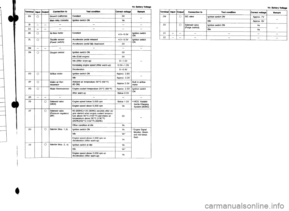
VE Batmy voltage
1 Ve: Battery vm
i
Remark
Termfnal Input Output Connection lo
Test conditkm
colmct voltage Remark
2W
0 Iscvalve lgmtian swdch ON
Approx. iv
-
Idle Appror. 9v
2x
0 Solenoid valve
lgnitlon switch ON
VS
(Purge control) -
IUk
VB
2Y - - -
-
-
@i switch
)N le
I!
C
4
-C
,
,
e
”
3
-C
.
f
-
-
-
)nition switch
)N I I I
I I
I -
22 - - -
- -
-
-
-
luilt in airflow
1eter
lnition swttch
)N
-
VICS: Vata&
Inertia charging
SYStem loaHCl
-
Engine Signal
Monitor: Green
and red lamps
flash
mnin
2H
- I Main relay (w=w I Ignition switch ON
VB
_/I/ - I -
I - 21
25
-7 I - I -
I - , I t 0 Air-flow meter constant
4.5-5.5v 2K
I I I
I
0 I 1 Thr0tlle sensor Accekrator pedal r&eased
4.5-5-W
I I (Power switch)
Accelerator pedal fuUy depessed ov
2M
l-l - I -
-
I -
0 oxygen sensw Ignitia switch ON
ov
Idle (Cold engine) ov
Idle (After “ram-up)
O-l .ov
Increasing engine speed (After warm-up) 0.5v-1 .ov
oeceleratlon
0-0.4v
0 Airflow meter Ignition switch ON
Ap~rox 3 8L
ldk Approx. 3.3 2N
20
2P
0 Intake air ther- Ambient air temperature 20°C (68” F)
mosensor
W W Ap&xox 2 5V
0 water thermosensor Enaine coolant temperature 20°C (68°F)
ADDTOX 2.5\( 20
2R
2s
,.
After “am-up B&w 0 5v
I I I I
- - - - -
0 Sdenoid valve Engine speed below 5.000 rpm Below 1 5v
ww
Engine speed above 5.000 rpm VB
2T I 0 lsolertoid valve
I60 jDOHCl/l20 ISOHCI seconds after en- 1
/ I--
temperature abo& 56°C (136 o F)
(OOHC]/SO”C (122°F) (SOHC]
0 Injector (Nos. 1.3) Other condition at idle VB
Ignition switch ON
Vt7
Idle
VB‘ 2u
2v Engine speed above 2.000 rpm on
decderation (After warm-up) Ve
0 Injector (NOS. 2. 4) Ignition swatch at id& VB
idle
VS.
Engine speed above 2,000 rpm on
deceteratiin (After warm-up) VS
Page 1090 of 1164
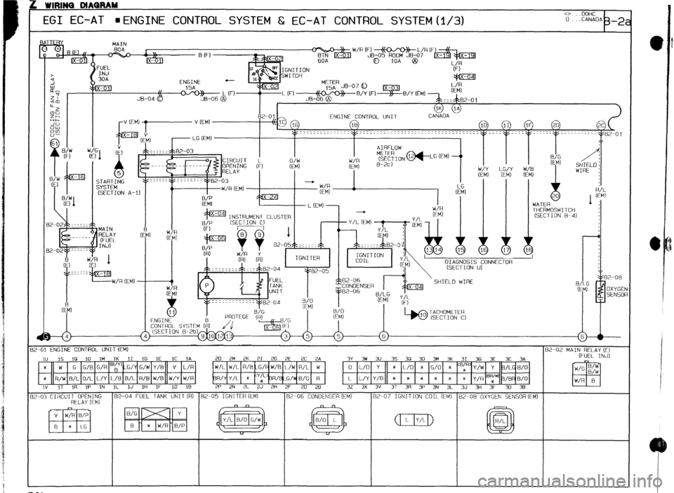
L WIRINQ DIAQRAM
EGI EC-AT HENGINE CONTROL SYSTEM 6 EC-AT CONTROL SYSTEM(1/3) <>. .DoHC 0 .ChNADh b-2
THERMOSWITCH
(SECTION 8-41 MAIN
- -
INSTRUMENT CLUSTER
+ Y/L (EM)
I I I I
Q
I
DIAGNOSIS CONNECTOR
(SECTION u)
II R/L
(EM)
1 ;
2-01 ENGINE CONTROL UNIT (EM)
162-02 MAIN RELAY (ET
1” IS 10 10 IM 1K 31 IG 1E IC 1A
x w G G/B G/R “,$%G,‘Y G/W Y/B V L/R
x R/W 0/L O/L L/Y C/B B/L R/B W/B w/y W/R
,” ,T 117 ,P IN 3L IJ 1H IF 10 16 20 2M 2K 21 26 2E 2C 2A
/L W/L R/B -G/ W/E L/W R/L W
R/Y Y/L * “t R/%-G/k B/G R
2P 2N 2L 2J 2H 2F 2D 28 3Y 3W 3U 35 30 30 3M 3K 31 36 3E 3C 3A (FUEL INJ)
0 L/O Y 3c L/O * G/O *
BpJY/W Y 3/L B/O
L L/Y Y/B * x * * *
* Y/R yp’ 3/B B/O
32 3X 3V 3T 3R 3P 3N 3lL 3J 3H 3F 30 38
2-03 CIRCUIT OPENING 82-04 FUEL TANK UNIT(R) 82-05 IGNITER (EM1 82-06 CONDENSER (EM) 82-07 IGNITION COIL (EM)
RELAY iEM)
B/G
B 82-08 OXYGEN SENSOR (EM)
z-34