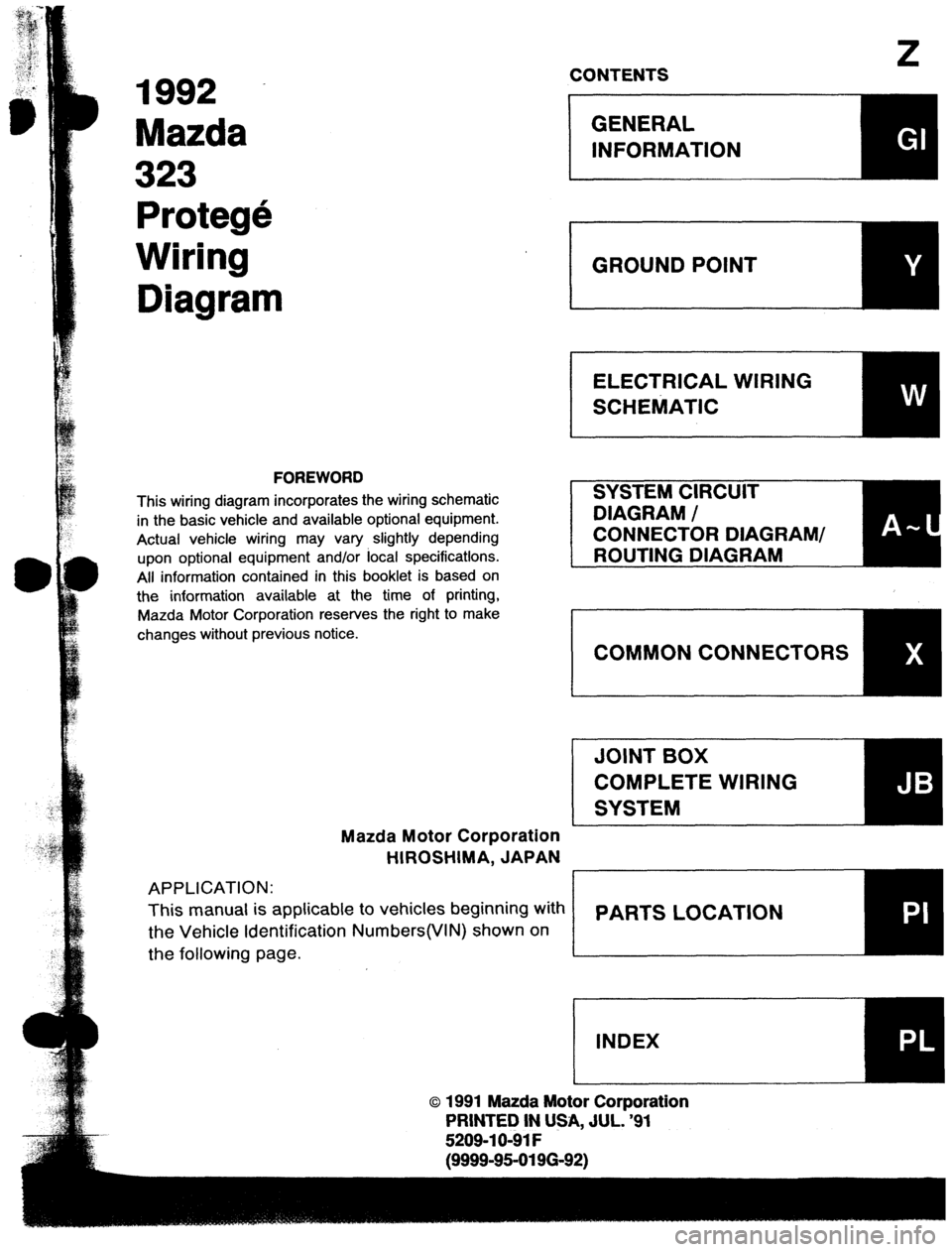
1992 MAZDA PROTEGE wiring diagram
[x] Cancel search: wiring diagramPage 267 of 1164

F
FUEL AND EMISSION
CONTROL SYSTEM
INDEX ...........................................
OUTLINE ...................................... ;: 2
SYSTEM DIAGRAM ...................... F-
:
VACUUM HOSE ROUTING
DIAGRAM .................................
WIRING DIAGRAM ....................... F- 6
- 7
ENGINE CONTROL UNIT (ATX) ...... F- 13
SPECIFICATIONS.. ....................... F- 15
COMPONENT DESCRIPTIONS.
...... F- 16
TROUBLESHOOTING GUIDE.. ......... F- 20
ENGINE CONTROL OPERATION
CHART
..................................... F- 20
RELATIONSHIP CHART.. .............. F- 24
USING THIS SECTION .................. F- 25
DIAGNOSTIC INDEX .................... F- 27
PRECAUTION ............................. F- 29
SYMPTOM TROUBLESHOOTING .... F- 30
ENGINE TUNE-UP
.......................... F- 76
PREPARATION ............................
F- 76
BASIC INSPECTION ..................... F- 78
ADJUSTMENT .............................
F- 79
SELF-DIAGNOSIS FUNCTION .......... F- 82
DESCRIPTION .............................
F- 82
PREPARATION
............................
F- 83
SERVISE CODE NUMBER.. ........... F- 83
SWITCH MONITOR FUNCTION ...... F-105
INTAKE AIR SYSTEM.. ................... F-109
COMPONENT PARTS.. ................. F-109
THROTTLE BODY ........................ F-l 12
DYNAMIC CHAMBER ................... F-l 12
INTAKE MANIFOLD ..................... F-l 13
ACCELERATOR PEDAL ................ F-l 14
ACCELERATOR CABLE ................ F-l 14
IDLE SPEED CONTROL (ISC)
SYSTEM ......................................
F-115
DESCRIPTION ............................. F-115
PREPARATION
............................ F-116
SYSTEM OPERATION.. ................. F-l 16
ISC VALVE ................................. F-116
AIR VALVE
................................. F-116
VARIABLE INERTIA CHARGING
SYSTEM (VICS) [DOHC] ................ F-l 17
DESCRIPTION ............................. F-117
SYSTEM OPERATION ................... F-l 18
SHUTTER VALVE ACTUATOR.. ...... F-l 18
SOLENOID VALVE (VICS). ............. F-118
VACUUM CHAMBER.. .................. F-119
FUELSYSTEM .............................. F-l 20
DESCRIPTION
............................. F-l 20
PRECAUTION ............................. F-121
SYSTEM OPERATION.. ................. F-121
FUEL TANK ................................
F-l 23
FUEL FILTER .............................. F-l 24 FUEL PUMP ............................... F-l 25
CIRCUIT OPENING RELAY.. .......... F-129
PRESSURE REGULATOR.. ............ F-129
INJECTOR .................................. F-l 31
PRESSURE REGULATOR
CONTROL SYSTEM.. .................... F-l 34
SOLENOID VALVE (PRESSURE
REGULATOR CONTROL). ............ F-l 35
EXHAUST SYSTEM ........................ F-l 36
COMPONENT PARTS.. ................. F-136
OUTLINE OF EMISSION
CONTROL SYSTEM.. .................... F-l 37
STRUCTURAL VIEW.. ................... F-l 37
POSITIVE CRANKCASE
VENTILATION (PCV) SYSTEM.. ..... F-138
DESCRIPTION .............................
F-l 38
PCV VALVE ................................ F-l 38
EVAPORATIVE EMISSION
CONTROL SYSTEM.. .................... F-l 39
DESCRIPTION ............................. F-l 39
SYSTEM OPERATION.. ................. F-140
SOLENOID VALVE
(PURGE CONTROL) ................... F-140
SEPARATOR ............................... F-l 40
CHECK VALVE (TWO-WAY) ........... F-140
CHECK-AND-CUT VALVE.. ............ F-141
CHARCOAL CANISTER.. ............... F-141
DECELERATION CONTROL
SYSTEM ...................................... F-l 42
DESCRIPTION ............................. F-l 42
DASHPOT .................................. F-142
FUEL CUT CONTROL SYSTEM ....... F-143
DESCRIPTION ............................. F-l 43
PREPARATION ............................ F-l 43
SYSTEM OPERATION.. ................. F-143
DECHOKE CONTROL SYSTEM.. ...... F-145
DESCRIPTION ............................. F-l 45
SYSTEM OPERATION ................... F-l 45
CONTROL SYSTEM ....................... F-l 47
PREPARATION ............................ F-147
STRUCTURAL VIEW.. ................... F-l 48
ENGINE CONTROL UNIT (ECU) ..... F-149
AIRFLOW METER (WITH INTAKE AIR
THERMOSENSOR) ..................... F-168
WATER THERMOSENSOR.. ........... F-168
THROTTLE SENSOR .................... F-l 69
OXYGEN SENSOR.. ..................... F-171
MAIN RELAY (FUEL INJ RELAY) .... F-172
CLUTCH SWITCH (MTX) ............... F-172
NEUTRAL SWITCH (MTX). ............. F-173
POWER STEERING PRESSURE
SWITCH .................................... F-173
WJOFX-001
Page 368 of 1164

SELF-DIAGNOSIS FUNCTION
:ODE No. 1 25 (SOLENOID VALVE - PRESSUREREGULATORCONTROL)-BPENGINE
r (
TEP
1
-
2
-
3 I
INSPECTION
Disconnect connector from ECU and check if
battery voltage exists at ECU terminal 2T (MTX)
3M (ATX) wire (G/O) with ignition switch ON
In same condition as Step 1, check if battery
voltage exists at solenoid valve connector
terminal-wire (G/O) ACTION
Yes Check ECU terminal connector for poor -
connection
* If OK, replace ECU CT page F-149
+
If not OK, repair or replace connector
No Go to next step
Yes Repair or replace wire (G/O)
No Go to next step
Check if solenoid valve is OK Yes Check for short or open circuit in wiring
w page F-135 from main relay (FUEL INJ relay) to
solenoid valve
No Replace solenoid valve
I I I
23UOFX-077
:ODE No. 26 (SOLENOID VALVE - PURGE CONTROL)
STEP INSPECTION
Disconnect connector from ECU and check if
battery voltage exists at ECU terminal 2X (MTX)
20 (ATX) wire harness (W/L) with ignition switch
ON Yes
No
In same condition as Step 1, check if battery
Yes
voltage exists at solenoid valve connector
terminal-wire (W/L)
No
Check if solenoid valve is OK
Yes
w page F-140
t- No
--
4 ACTION
Check ECU terminal connector for poor
connection
ti If OK, replace ECU c;p page F-149
e
If not OK, repair or replace connector
Go to next step
Repair or replace wire harness (W/L)
Go to next step
Check for short or open circuit in wiring
from main relay (FUEL INJ relay) to
Circuit Diagram
MTX
I-
FROM
BATTERY
FROM
23UOFX-07 9
F-l 02
Page 369 of 1164

SELF-DIAGNOSIS FUNCTION F
1
CODE No. 34 (ISC VALVE)
1 ACTION
Yes Check ECU terminal connector for poor
connection INSPECTION
Disconnect connector from ECU and check if
battery voltage exists at ECU terminal 2W (MTX)
3Q (ATX) wire (L/O) with ignition switch ON
c3 If OK, replace ECU
+ If not OK, repair or replace con-
nector w page F-149
No Go to next step
In same condition as Step 1, check if battery
voltage exists at ISC valve connector terminal.
wire (L/O) Yes ) Repair or replace wire (L/O)
No Go to next step
Yes Check for short or open circuit in wiring
from main relay (FUEL INJ relay) to ISC
valve
No Replace ISC valve Check ISC valve for correct resistance
w page F-i 16
Resistance: 1 l-130 [at 20°C(68”F) ]
I 23UOFX-08( I
r C :ODE No. )
41 (SOLENOID VALVE - VICSbDOHC
I
ii
T
I
INSPECTION
ACTION
Check ECU terminal connector for poor
connection
in’
I
* If OK, replace ECU w page F-149
c3 If not OK, repair or replace con-
nector
No Go to next step Disconnect connector from ECU and check if
battery voltage exists at ECU
terminal 2S (MTX)
31 (ATX) wire (B/R) with ignition switch ON
2 In same condition as Step 1, check if battery voltage exists at solenoid valve connector
terminal-wire (B/R)
Check if solenoid valve is OK
w page F-l 18 Yes Repair or replace wire (B/R)
No Go to next step
Yes Check for short or open circuit in wiring
from main relay to solenoid valve
No
Replace solenoid valve
23UOFX-081 3
Circuit Diagram
ATX
ISC VALVE
FROM
BATTERY 4
FROM
L
IGNITION d++n.D,,
SWITCH
MAIN RELAY
(FUEL INJ RELAY) S
4\ ECU
SOLENOID VALVE
i(VICS) [DOHC]
W/R ,,
\
SOLENOID VALVE ,
(PURGE CONTROL)
23UOFX-082
F-i 03
Page 865 of 1164

OUTLINE
OUTLINE
HOW TO USE THIS SECTION
Information regarding removal and installation of electrical equipment is given in SECTION S.
Understanding will be easier if this section is used in conjunction with the WIRING DIAGRAMS.
9MUOTX-008
1.4W or 3.4W
23UOTX.07 1
61G15X-002
69G15X-00 3
63U 15X-005
ELECTRICAL TROUBLESHOOTING TOOLS
Test Light
The test light, as shown in the figure, uses a battery voltage
bulb. The two leads should be connected to probes. The test
light is used for simple voltage checks and to check for open
circuits.
Caution
l When checking the control unit, never use a bulb
over 3.4W.
Jumper Wire
The jumper wire is used for testing by short-circuiting switch
terminals and for verifying the condition of ground connections.
Caution
l Do not connect the jumper wire between a power
source line and body ground because this may
cause burning or other damage to harnesses or
electronic components.
The DC voltmeter is used for measuring circuit voltage. A volt- q Voltmeter
meter with a range of 15V or more is used by connecting the
positive (+) probe (red lead) to the point where voltage is to
be measured, and the negative (-) probe (black lead) to the
body ground.
Ohmmeter
The ohmmeter is used to measure the resistance between two
points in a circuit, and is also used to check for continuity and
diagnosis of short circuits.
Caution
l Do not attempt to connect the ohmmeter to any cir-
cuit to which voltage is applied because this may
burn or otherwise damage the ohmmeter.
T-9
Page 914 of 1164

T WARNING SYSTEM
WARNING SYSTEM
WARNING BUZZER AND TIMER
Circuit Diagram
WARNING LAMP
REAR WIPER SW
RASSIVE CONTROL UNIT
Inspection
Remove the CPU and check the voltage or continuity between terminals of joint box and a body ground.
Key reminder alarm does not sound.
VB: Battery voltage
Terminal Connected to Test condition Specification To correct
I
Key reminder switch Key in cylinder VB Check ignition switch and
(ignition switch) Key out bf cylinder ov wiring harness
(Refer to page T-21)
P Ignition switch Ignition switch ON
‘/B Check ignition switch and
wiring harness
(Refer to page T-21)
N Door switch Any door open ov Check door switches and
All doors closed VS wiring harness
(Refer to page T-51)
23UOTX-031
T-58
Page 1054 of 1164

1992
Mazda
323
Protege
Wiring
Diagram
FOREWORD
This wiring diagram incorporates the wiring schematic
in the basic vehicle and available optional equipment.
Actual vehicle wiring may vary slightly depending
upon optional equipment and/or focal specifications.
All information contained in this booklet is based on
the information available at the time of printing,
Mazda Motor Corporation reserves the right to make
changes without previous notice.
Mazda Motor Corporation
HIROSHIMA, JAPAN
APPLICATION:
This manual is applicable to vehicles beginning with
the Vehicle Identification Numbers(VIN) shown on
the following page.
z CONTENTS
o 1991 Mazda Motor Corporation
PRINTED IN USA, JUL. ‘91
5209-l O-91 F
E (9999-95-0196-92)
Page 1057 of 1164

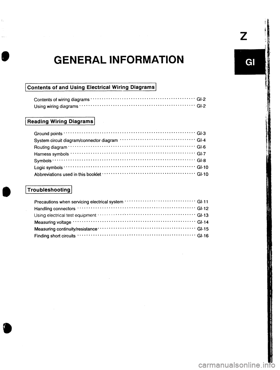
GENERAL INFORMATION
Contents of and Using Electrical Wiring Diagrams
Contents of wiring diagrams . . . . . . . . . . . . . ..I.............................
Using wiring diagrams * * * * * . * * . . . . . . . . . . . . . ..I..........................
I
( Reading Wiring Diagrams
* GI-2
* GI-2
Ground points . * .........................................................
GI-3
System circuit diagram/connector diagram * * . * ..............................
GI-4
Routing diagram ............................... ..........................
GI-6
Harness symbo,s ................................. ....................... G,-,
Symbols”““” ........................................................
GI-8
Logic symbols ...........................................................
GI-10
Abbreviationsusedinthisbook,et..........................................GI-, 0
Troubleshooting
Precautionswhenservicingelectricalsystem”””””””““““““““” GI-11
Handling connectors .....................................................
GI-12
“sing electrical test equipment ............................................. Gl-13
Measuring voltage .......................................................
GI-14
Measuring continuity/resistance ............................................
GI-15
Finding short circuits .....................................................
GI-16
Page 1058 of 1164

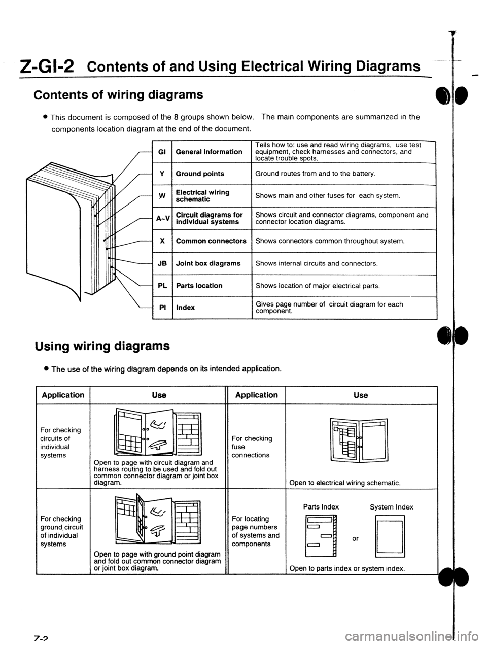
Z-Gl-2 Contents of and Using Electrical Wiring Diagrams
Contents of wiring diagrams
l This document is composed of the 8 groups shown below. The main components are summarized in the
components location diagram at the end of the document.
Tells how to: use and read wiring dragrams, use test
GI General information equipment, check harnesses and connectors, and
locate trouble spots.
Y Ground points Ground routes from and to the battery.
I
w
I Electrical wiring
schematic
I Shows main and other fuses for each system.
lndlvidual systems
I Shows circuit and connector diagrams, component and
connector location diagrams.
1
X
I Common connectors
I Shows connectors common throughout system.
I
JB Joint box diagrams Shows internal circuits and connectors.
PL Parts location Shows location of major electrical parts.
PI Index
I
I
Gives page number of circuit diagram for each
component.
Using wiring diagrams
l The use of the wiring diagram depends on its intended application. Application
For checking
circuits of
individual
systems
For checking
ground circuit
of individual
systems 7-3 Use
II Application
Open to page with circuit diagram and
harness routing to be used and fold out
common connector diagram or joint box
diagram. For checking
fuse
connections Use
Open to electrical wiring schematic.
Open to page with ground point diagram
and fold out common connector diagram
or joint box diagram. For locating
page numbers
of systems and
components Parts Index
H
Open to parts index or system index.