1992 MAZDA PROTEGE ignition
[x] Cancel search: ignitionPage 1096 of 1164
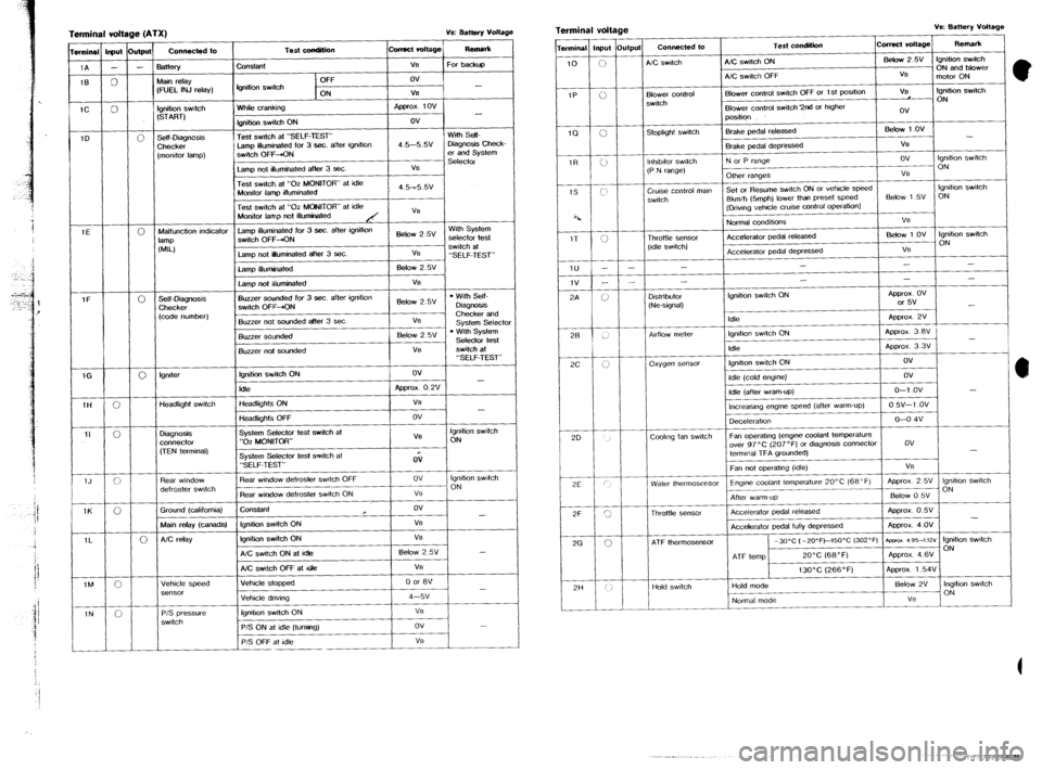
Terminal vdt
wminal lrput
1A -
1B 0
-
1C 0
1D e (ATX) ve: aattefy voltage
1
Connected to
I Test wndition ~cwrect rc4t.gej F&W*
-
0
-
-
3attery
Uain r&y
:FUEL INJ relay) Constant
tgnition swdch V% For backt@
OFF ov
ON V6
Ignition swtch
(START)
Self-Diagnosis
Checker
[monitor lamp)
3 - White crankii npprox 1ov
fgnition switch ON ov
Test swtch at “SELF-TEST’ With Self-
Lamp illuminated for 3 sec. after igmtmn 4.5-5.w Diagnosis Check-
switch OFF-+ON er and System
Selector
Lamp net illuminated after 3 Sec. VS
Test swtch at “02 MONITOR” at idle
i Monitor lamp illuminated 4.5-55v
Test switch at “02 MONtTOR” at idfe
Monitor lamp not illuminated
Malfunction indicator
lamp illuminated for 3 sec. after ignition
Below 2 5v With System
lalllp switch OFF+ON selector test
WLI switch at
Lamp not luminated after 3 sec. VE
“SELF-TEST”
lamp ifluminated BelOW 2.w
Lamp not illuminated VS
Self-Diagnosis Buzzer sounded for 3 sec. after ignrtion
l With Self-
Checker switch OFF-+ON Below 2.5V
Diagm!3s
(code number) Checker and
Buzzer not sounded after 3 set VB
system
Select0 Buzzer sou&?d Below 2 5v l With System
Selector test
I Buzzer not sounded
tgmter Ignition switch ON ov
Idle Appror 0 2v -
Headlight switch Headlights ON
f VB
-
Headlbhts OFF ! ov
Diagnosis
connector
, System Selector test switch at
VS Ignition witch
“02 MONITOR” ON
(TEN terminal)
Rear window
defroster switch
Ground Icalifornia) System Selector tesf switch at
“SELF-TEST”
Rear window defroster watch OFF
Rear window de!roster watch ON
ConSlant QV
ov lgmhon switch
__ ON
VO
ov
- Main relay (canadal fgmtion switch ON VB
AC relay Ignitiin switch ON VB
A/C switch ON at Idle Below 2.5% -
Vehicle speed A/C switch OFF at Gle
/ Vehicle stopped
P/S pressure
switch lgmhon switch ON
P/S ON at idle Iturnino)
I.
P/S OFF at idle I VB Terminal voltage v‘s: Battery vottage
I I
1
Terminal input Output Connected to Test condition comcl voltage Remark
10
0 A/C swatch AIC switch ON Befow25V ignition switch
ON and blower
A/C switch OFF VB I
motor ON
IP
ii Blower control Blower control swtch OFF or 1 St poSItion VB tgnibon switch
switch ON
Blower control switch 2nd or higher
ov
position
1Q
0 Stopltght switch Brake pedal released Below 1 ov
-
IT <; Brake pedal depressed VE
lnhtbitor switch N or P range ov Ignition switch
(P N range) ON
Other ranges VB
Cruise control man Set or Resume swtch ON or vehicle speed lgmhon swtch
switch 8kmih &mph) lower than preset speed &tow 1 5~ ON
(Drwng vehcfe crwse cantrol
OperatiOn)
Fk
z 1v -
3A ’ Throttle Sensor
(Idle switch) Normal conditions
Accelerator pedal released
Accelerator pedal depressed “8
Bebw 1 ov lgnihon swatch
ON
VS
I -
-
- - -
-
-
- - -
D&rib&r
-‘. / b / / (Ne-signal) lgmtion swtch ON
/ ,,,, Approx. OV
or 5v
-
Approx 2v
I ._.
/
28 1
AdlOw meter lgmhon switch ON
Approx 3 BV .,
-
Idle Approx 3 3V
2c j r:
I \’ oxygen sensor fgmtson switch ON ov
1
20 Idle (cold englIIei
Idle (after warn-up)
lncreasma enwe speed (after warm-up) ov
O-l ov -
0 w-1 .ov
_ -
,
Deceleration o-o 4v
Coolmg fan swtch Fan operahng (engine coolant temperature
over 97°C (207’F) or diagnosis connector DV
termmat TFA grounded) -
Fan not operatmg (idle)
Water thermosensor Engine codant temperature L” %, I”” I , ‘Y”8’.“” . . . ...-1.
After warm-up
I
Thrnttb SP”SOi 1 Accelerator pedal released Approx 0.5V
2G .._..._ --..--
-
Accelerator pedal fully depressed Approx. 4 OV
0 ATF thermosensor -XPC (-2o”~)--1x1~c (302°F) aprxox as5-~m lgmhon swtch
ON
ATF temp 20°C (68°F) Approx. 4.6V
13OOC (266°F) Aporox 1.54V
I I I I I I
2H / i, I / Hold switch Hold mode Below 2V Ingbhon switch
Normal mode
Page 1097 of 1164
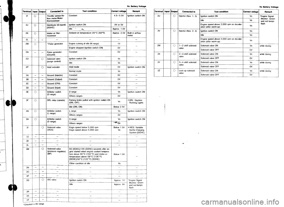
fgnltio” switch ON Ve Battery von%ge
rrmin%l Inpu( Output
Connected to
3u
0 Injector (Nos 1, 3)
I Test condition curact von%ge Remmk r 1 lon~tii switch ON I
I
VB 1 ‘Enaine S~anal
Idle
Engine speed above 2.000 rpm on deceler-
atton (after warm-up) V%
VB Monitor: Green
and red lamps
fksh
3v
3w
3x 0 Injector (Nos. 2. 4) Ignition switch ON VB
tdk VS
Engine speed above 2,000 rpm on dec%kr-
atlo” (after warm-up) VS
ci 1-2 shift soknold Solenoid valve ON V%
whtk during
valve
Soknold valve OFF ov
0 2-3 shrft solenoid Soknold valve ON
V% wh6k during
valve
Solenoid valve OFF ov
3Y
32 0 3-4 shift solenoid Solenoid valve ON
vs while during
valve
Solenoid valve OFF ov
0 Lock up solenoid Solenoid valve ON
V% while during
valve
Soknoad valve OFF ov
i
Page 1130 of 1164
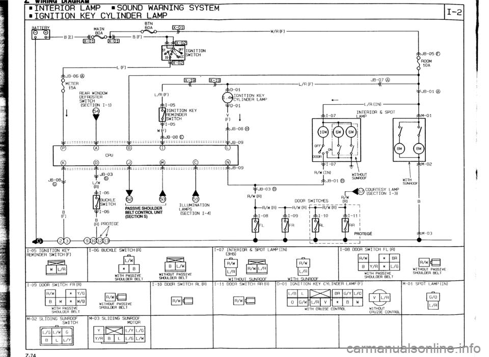
h ntnwJu lJlAUc(Arn
. INTERIOR LAMP l SOUND WARNING SYSTEM
QGNITION KEY CYLINDER LAMP
BTN
COURTESY LAMP
(SECTION I-3)
EECTION I-41
-05 IGNITION KEY
IEMINOER SWITCH(F) :
I
M
z-74
I-06 BUCKLE SWITCH (R) I-07 INTERIOR 6 SPOT LAMPtIN)
I-08 DOOR SWITCH FL (R)
SHOULDER BELT
YfOULCER BELT S%XlLOER BELT
WITHOUT SUNROOF WITH SUNROOF SHOULDER BELT
-09 DOOR SWITCH FR (R) I-IO ODOR SWITCH RL(RI I-11 DOOR SWITCH RR(R) D-01 IGNITTON KEY CYLINDER LAMP(F)
M-01 SPOT LAMP {IN)
WITH CRUISE CONTROL
SHOULDER BELT
CRUISE CONTROL
-02 SLIDING SUNROOF M-03 SLIDING SUNROOF
SWITCH MOTOR -
Page 1149 of 1164
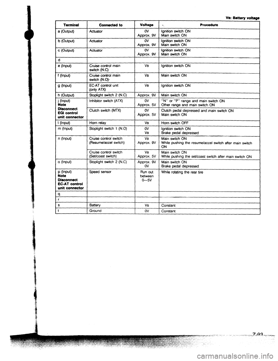
Vs: Battery voltags
Terminal Connecte4t to
Voltage . . . Procedure
a (Output) Actuator ov Ignition switch ON
Approx. 9V Main switch ON
b (Output) Actuator ov Ignition switch ON
Approx. 9V Main switch ON
c (Output) Actuator ov Ignition switch ON
Approx. 9V Main switch ON
d
e (Input) Cruise control main VEI Ignition switch ON
switch (N.C)
f (input) Cruise control main Ve Main switch ON
switch (N.0).
9 Wwft) EC-AT control unit VI3 Ignition switch ON
(only ATX)
h (Output) Stoplight switch 2 (NC) Approx. 9V Main switch ON
i (Input) Inhibitor switch (ATX) ov “N” or “P” range and main switch ON
Note Approx. 5V Other range and main switch ON
Disconnect
EGI control Clutch switch (MTX) ov
Clutch pedal depressed and main switch ON
unit connector Approx. 5V Main switch ON
I (Input) Horn relay VB Horn switch OFF
m (Input) Stoplight switch 1 (N.0) ov Ignition switch ON
VEI
Brake pedal depressed
n (Input) Cruise control switch VE Main switch ON
(Resumelaccel switch) Approx. 9V While pushing the resume/accel switch after main switch
ON
Cruise control switch VEI Main switch ON
(Set/coast switch) Approx. 5V While pushing the set/coast switch after main switch ON
0 (Input) Stoplight switch 2 (N.C) Approx. 9V Main switch ON
ov
Brake pedal depressed
P (Input) Speed sensor Run out
Note While rotating the rear tire
between
O&connect 0-w
EC-AT control
unit connector
q
r
S Battery Vs
Constant
t Ground ov
Constant
Page 1152 of 1164
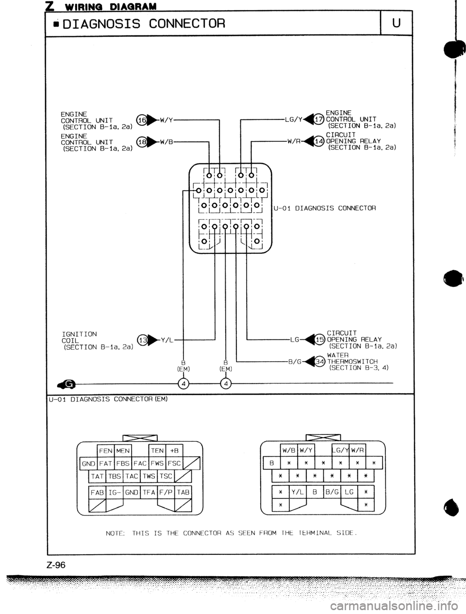
. WIIWNU UIAUnA-
iDIAGNOSIS CONNECTOR U
ENGINE
CONTROL UN IT (SECTION B-la. 2a) @-W/Y (SECTION B-la. 2al
ENGINE
CONTROL UNIT
(SECTION
B-la, 2a) *W/B (SECTION B-la. 2a)
U-01 DIAGNOSIS CONNECTOR
IGNITION
COIL
(SECTION
J-01 DIAGNOSIS CONNECTOR (EM)
NOTE: TH-tS IS THE CONNECTOR AS ZEN FROM THE TERMINAL SIDE.
Z-96
Page 1162 of 1164
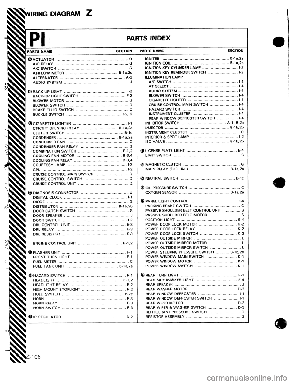
DIAGRAM Z
rl PARTS NAME
-
PA ,K
SECTION T
CIGARETTE LIGHTER ............................................
I-1
CIRCUIT OPENING RELAY ..............................
B-l&Pa
I CLUTCH
SWITCH .............................................. B-lc
CONDENSER ................................................. B-la.2a
CONDENSER FAN ..................................................
G
CONDENSER
FAN RELAY ....................................... G
COMBINATION
SWITCH .................................... E-l.2
COOLING FAN MOTOR .....................................
B-3,4
COOLING
FAN RELAY ........................................ B-3,4
COURTESY LAMP ................................................
l-3
CPU .................................................................... l-2
CRUISE CONTROL
MAIN SWITCH ........................... Q
CRUISE
CONTROL SWITCH .................................... Q
CRUISE CONTROL UNIT ......................................... Q 0 ACTUATOR ........................................................... Q
A/C RELAY ........................................................... G
t A/C SWITCH .........................................................
G
t AIRFLOW METER .......................................... B-lc,Pc
t ALTERNATOR .....................................................
A-2
I AUDIO SYSTEM .....................................................
J
@BACK-UP LIGHT .................................................. F-3
BACK-UP LIGHT SWITCH
..................................... F-3
I
BLOWER MOTOR ...................................................
G
h BLOWER SWITCH ..................................................
G
I BRAKE FLUID SWITCH ...........................................
C
BUCKLE SWITCH .............................................
l-2, S
@I DIAGNOSIS CONNECTOR .......................................
U
DIGITAL CLOCK
................................................... l-l
DIODE ..................................................................
G
DISTRIBUTOR ...............................................
B-l b,2b
DOOR CATCH SWITCH .......................................... S
DOOR
SPEAKER ..................................................... J
DOOR SWITCH ....................................................
l-2
DRL CONTROL UNIT ............................................
E-3
DRL RELAY .........................................................
E-3
ORL RESISTOR ....................................................
E-3
ENGINE CONTROL UNIT
.................................... B-1.2
ii@ FLASHER UNIT ....................................................
F-l
FRONT TURN LIGHT ............................................
F-l
FUEL METER
......................................................... C
FUEL
TANK UNIT .......................................... B-la,2a
HAZARD SWITCH ...............................................
F-l _
HEADLIGHT .....................................................
E-l.2
HEADLIGHT RELAY .............................................
E-2
h HIGH
MOUNT STOPLIGHT ....................................
F-2
h HOLD SWITCH .................................................. B-2c
4 HORN .................................................................
F-3
! HORN RELAY
...................................................... F-3
HORN SWITCH ....................................................
F-3
0 IC REGULATOR ..................................................
A-2
-L
T-S INDEX
PARTS NAME SECTION
IGNITER ........................................................ B-la,2a
IGNITION COIL ..............................................
B-la.2a
IGNITION KEY CYLINDER LAMP .............................
l-2
IGNITION KEY REMINDER SWITCH ........................ l-2
ILLUMINATION LAMP
A/C SWITCH ..................................................... l-4
AT SELECT
....................................................... l-4
AUDIO SYSTEM
................................................. l-4
BLOWER SWITCH .............................................
l-4
CIGARETTE LIGHTER
......................................... l-4
CRUISE CONTROL
MAIN SWITCH ....................... l-4
HAZARD SWITCH .............................................
l-4
INSTRUMENT CLUSTER
..................................... l-4
REAR WINDOW DEFROSTER SWITCH
................. l-4
INHIBITOR SWITCH .................................... A-l, B-2c
INJECTOR ....................................................
B-1 b,2b
INSTRUMENT CLUSTER ..........................................
C
INTERIOR & SPOT LAMP .......................................
l-2
ISC VALVE ...................................................
B-1 b,26
@ LICENSE PLATE LIGHT .........................................
E-4
LIMIT SWITCH .......................................................
S
481 MAGNETIC
CLUTCH .............................................. G
MAIN RELAY (FUEL INJ) ................................
B-la,Pa
@ NEUTRAL SWITCH ............................................
B-lc
@ OIL PRESSURE SWITCH ..........................................
C
OXYGEN SENSOR ......................................... B-la.2a
@ PANEL LIGHT CONTROL .......................................
l-4
PARKING BRAKE SWITCH ......................................
C
PASSIVE SHOULDER BELT CONTROL UNIT
.............. S
PASSIVE SHOULDER BELT
MOTOR .......................... S
POSITION LIGHT .................................................
E-4
POWER DOOR LOCK MOTOR
............................... K-2
POWER DOOR LOCK RELAY
................................. K-2
POWER DOOR LOCK SWITCH
.............................. K-2
POWER
OUTSIDE MIRROR ...................................... L
POWER OUTSIDE MIRROR MOTOR
.......................... L
POWER OUTSIDE MIRROR SWITCH .........................
L
POWER STEERING PRESSURE SWITCH ........... B-l b.2b
POWER WINDOW MAIN SWITCH .........................
K-l
POWER WINDOW MOTOR ...................................
K-l
POWER WINDOW SWITCH
.................................. K-l
@ REAR TURN LIGHT ..............................................
F-l
REAR SiDE MARKER LIGHT ..................................
E-4
REAR
SPEAKER ......................................................
J
REAR WASHER MOTOR ......................................
D-3
REAR WINDOW DEFROSTER
................................. I-1
REAR WINDOW DEFROSTER SWITCH ....................
I-1
REAR WIPER MOTOR
.......................................... D-3
REAR WIPER & WASHER SWITCH
........................ D-3
REFRIGERANT PRESSURE SWITCH
.......................... G
RESISTOR ASSEMBLY ............................................
G