Page 252 of 1216
7-4COOLING - Specifications
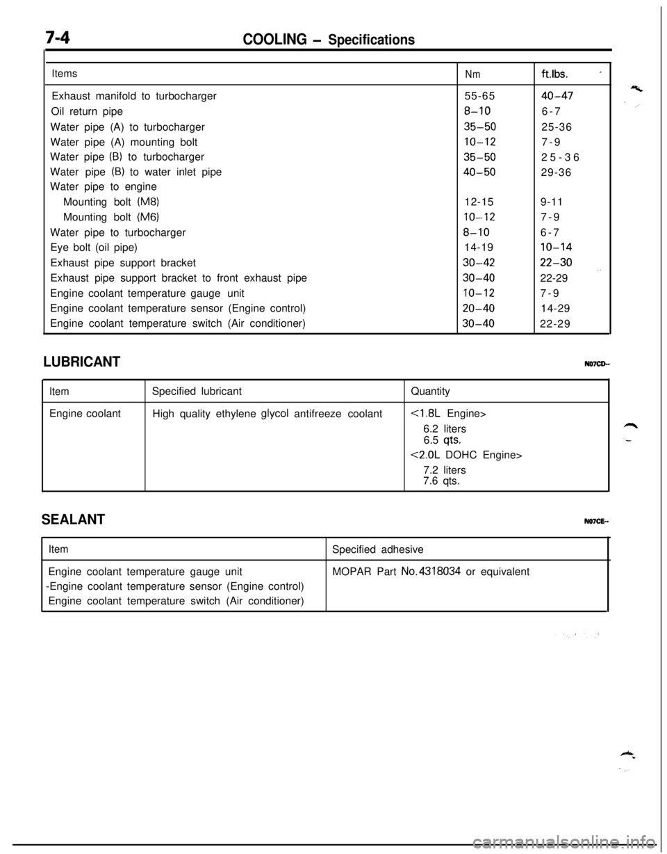
ItemsExhaust manifold to turbocharger
Oil return pipe
Water pipe (A) to turbocharger
Water pipe (A) mounting bolt
Water pipe
(B) to turbocharger
Water pipe
(B) to water inlet pipe
Water pipe to engine
Mounting bolt
(M8)Mounting bolt
(M6)Water pipe to turbocharger
Eye bolt (oil pipe)
Exhaust pipe support bracket
Exhaust pipe support bracket to front exhaust pipe
Engine coolant temperature gaugeunit
Engine coolant temperature sensor (Engine control)
Engine coolant temperature switch (Air conditioner)
Nmft.lbs. _155-65
40-47
8-106-7
35-5025-36
10-127-9
35-5025-36
40-5029-36
12-159-11
10-127-9
8-106-7
14-19
10-14
30-4222-30
30-4022-29 .’
10-127-9
20-4014-29
30-4022-29
LUBRICANT
ItemEngine coolantSpecified lubricant
High quality ethylene
glycol antifreeze coolantQuantity
6.2 liters
6.5
qts.
<2.0L DOHC Engine>
7.2 liters
7.6 qts.
SEALANTNO7CE-.
ItemEngine coolant temperature gauge unit
-Engine coolant temperature sensor (Engine control)
Engine coolant temperature switch (Air conditioner)Specified adhesive
MOPAR Part No.4318034 or equivalent
Page 253 of 1216
COOLING - Troubleshootina7-5
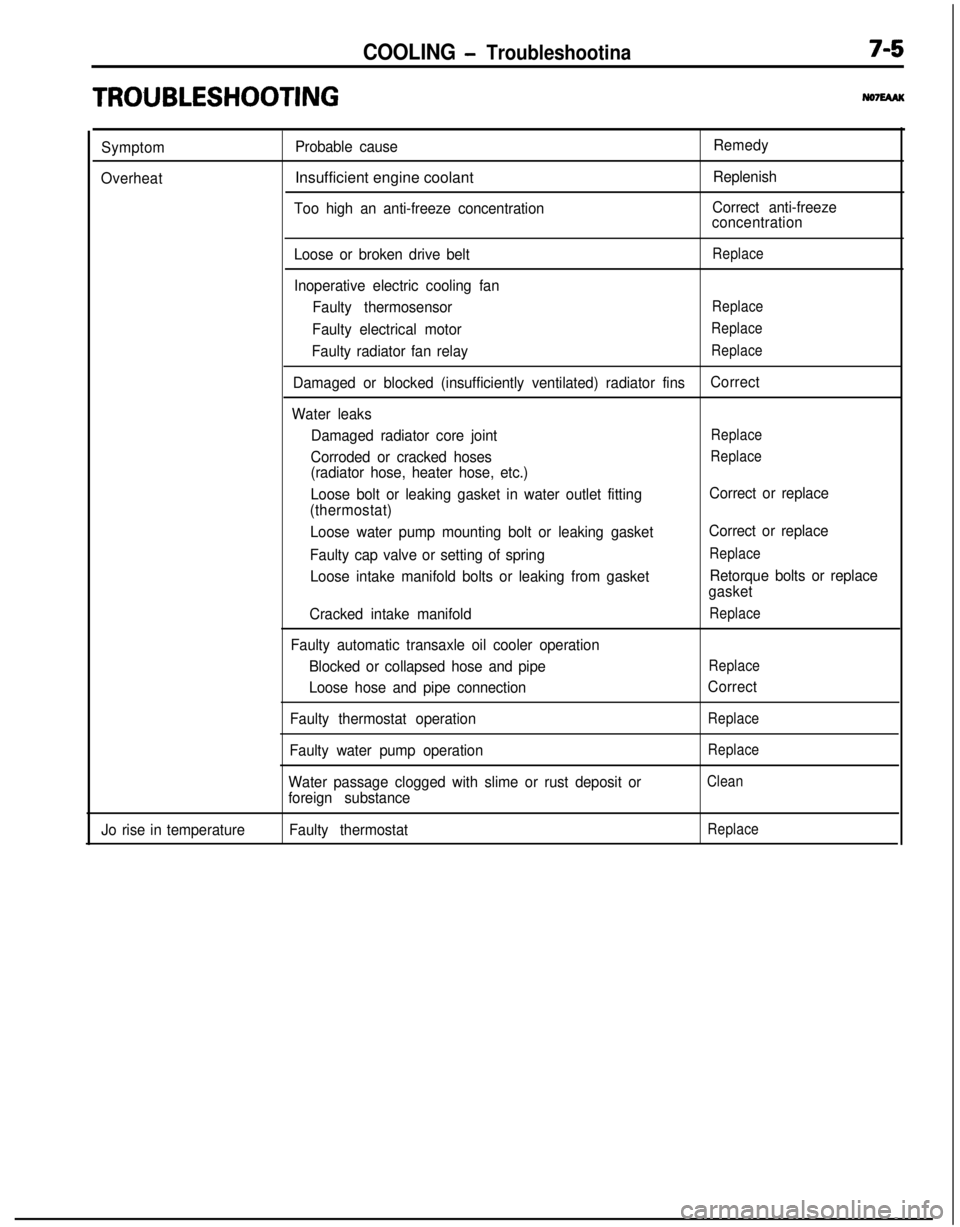
TRO,UBLESHOOTlNG
Symptom
OverheatProbable causeInsufficient engine coolant
Too high an anti-freeze concentrationRemedy
Replenish
Correct anti-freeze
concentration
Loose or broken drive belt
Replace
Inoperative electric cooling fan
Faulty thermosensor
Replace
Faulty electrical motorReplace
Faulty radiator fan relayReplace
Damaged or blocked (insufficiently ventilated) radiator finsCorrect
Water leaks
Damaged radiator core joint
Replace
Corroded or cracked hosesReplace
(radiator hose, heater hose, etc.)
Loose bolt or leaking gasket in water outlet fitting
(thermostat)
Loose water pump mounting bolt or leaking gasket
Faulty cap valve or setting of spring
Loose intake manifold bolts or leaking from gasket
Cracked intake manifold
Faulty automatic transaxle oil cooler operation
Blocked or collapsed hose and pipe
Loose hose and pipe connection
Faulty thermostat operation
Faulty water pump operation
Water passage clogged with slime or rust deposit or
foreign substanceCorrect or replace
Correct or replace
Replace
Retorque bolts or replace
gasket
Replace
Replace
Correct
Replace
Replace
Clean
Jo rise in temperatureFaulty thermostatReplace
Page 255 of 1216
COOLING - Troubleshooting7A7
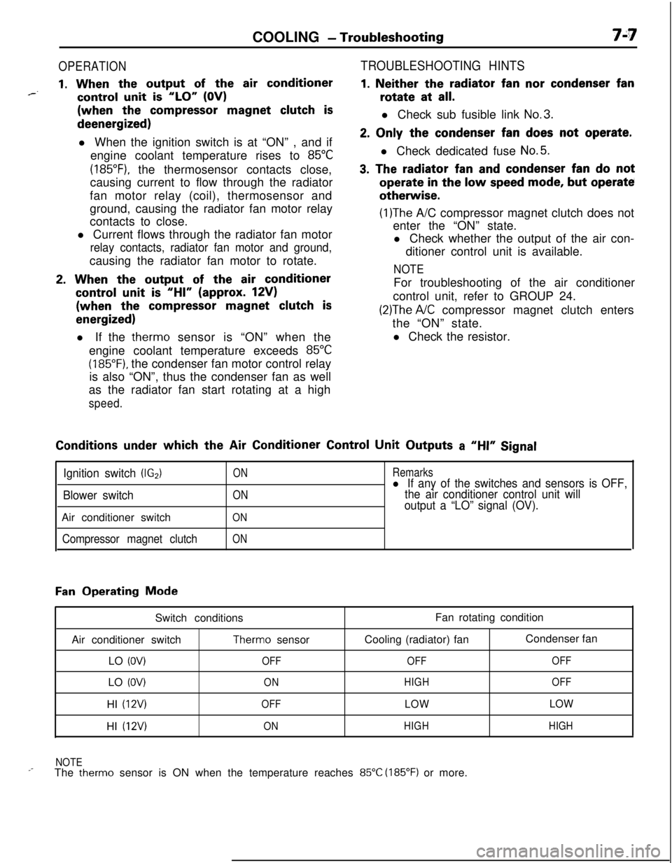
OPERATION
1. When the output of the air conditioner*--control unit is “LO” (OV)(when the
compressor magnet clutch isdeenergized)
l When the ignition switch is at “ON” , and if
engine coolant temperature rises to
85°C
(185”F), the thermosensor contacts close,
causing current to flow through the radiator
fan motor relay (coil), thermosensor and
ground, causing the radiator fan motor relay
contacts to close.
l Current flows through the radiator fan motor
relay contacts, radiator fan motor and ground,causing the radiator fan motor to rotate.
2. When the output of the air conditioner
control unit is “HI” (approx. 12V)(when the
compressor magnet clutch is
energized)l If the therm0 sensor is “ON” when the
engine coolant temperature exceeds
85°C
(185°F). the condenser fan motor control relay
is also “ON”, thus the condenser fan as well
as the radiator fan start rotating at a high
speed.
TROUBLESHOOTING HINTS
1. Neither the radiator fan nor condenser fanrotate at
all.l Check sub fusible link
No.3.
2. Only the condenser fan does not operate.l Check dedicated fuse
No.5.
3. The radiator fan and condenser fan do notoperate
in the low speed mode, but operateotherwise.
(1)The A/C compressor magnet clutch does not
enter the “ON” state.
l Check whether the output of the air con-
ditioner control unit is available.
NOTEFor troubleshooting of the air conditioner
control unit, refer to GROUP 24.
(2)The A/C compressor magnet clutch enters
the “ON” state.
l Check the resistor.Conditions
under which the Air Conditioner Control Unit Outputs a “HI” Signal
Ignition switch (IG2)
Blower switchAir conditioner switch
Compressor magnet clutch
ON
ON
ON
ON
Remarksl If any of the switches and sensors is OFF,
the air conditioner control unit will
output a “LO” signal (OV).
Fan Operating Mode
Switch conditions
Air conditioner switch
Therm0 sensor
LO
(OV)OFFLO
(OV)ONHI
(12V)OFFHI
(12V)ONFan rotating condition
Cooling (radiator) fanCondenser fan
OFFOFF
HIGHOFF
LOWLOW
HIGHHIGH
NOTE
_-The therm0 sensor is ON when the temperature reaches 85°C (185°F) or more.
Page 260 of 1216
7-12COOLING - Radiator
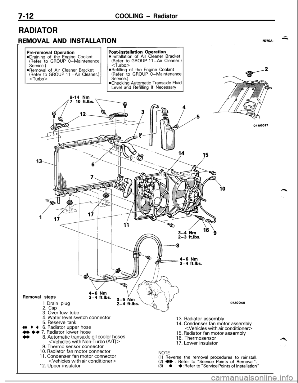
RADIATORPre-removal Operation
@Draining of the Engine Coolant(Refer to GROUP O-Maintenance(Refer to GROUP II-Air Cleaner.)
Service.)
I I
@Removal of Air Cleaner BracketORefilling of the Engine Coolant(Refer to GROUP 11 -Air Cleaner.)(Refer to GROUP O-MaintenanceService.)*Checking Automatic Transaxle FluidLevel and Refilling If Necessary
9-14 Nm
_
4-6 Nm3-4 ft.lbs.Removal steps
1 Drain plug2. Cap3. Overflow tube.
4-9 Nm3-4 ft.lbs.
4. Water level switch connector
5. Reserve tank~~ l +6. Radiator upper hose
+e e+ 7. Radiator lower hose
*I)8. Automatic transaxle oil cooler hoses9. Therm0 sensor connectorIO. Radiator fan motor connector
11. Condenser fan motor connector12. Upper insulator
04AOOS7
07A0049
13. Radiator assembly14. Condenser fan motor assembly15. Radiator fan motor assembly
16. Thermosensor
17. Lower insulator
NOTE(1) Reverse the removal procedures to reinstall.(2) +e : Refer to “Service Points of Removal”.(3) l + : Refer to “Service Points of Installation”
Page 261 of 1216
COOLING- Radiator7-13Mating
marks
04A0020
SERVICE POINTS OF REMOVALN07QBAH
6. REMOVAL OF RADIATOR UPPER HOSE/7. RADIATOR
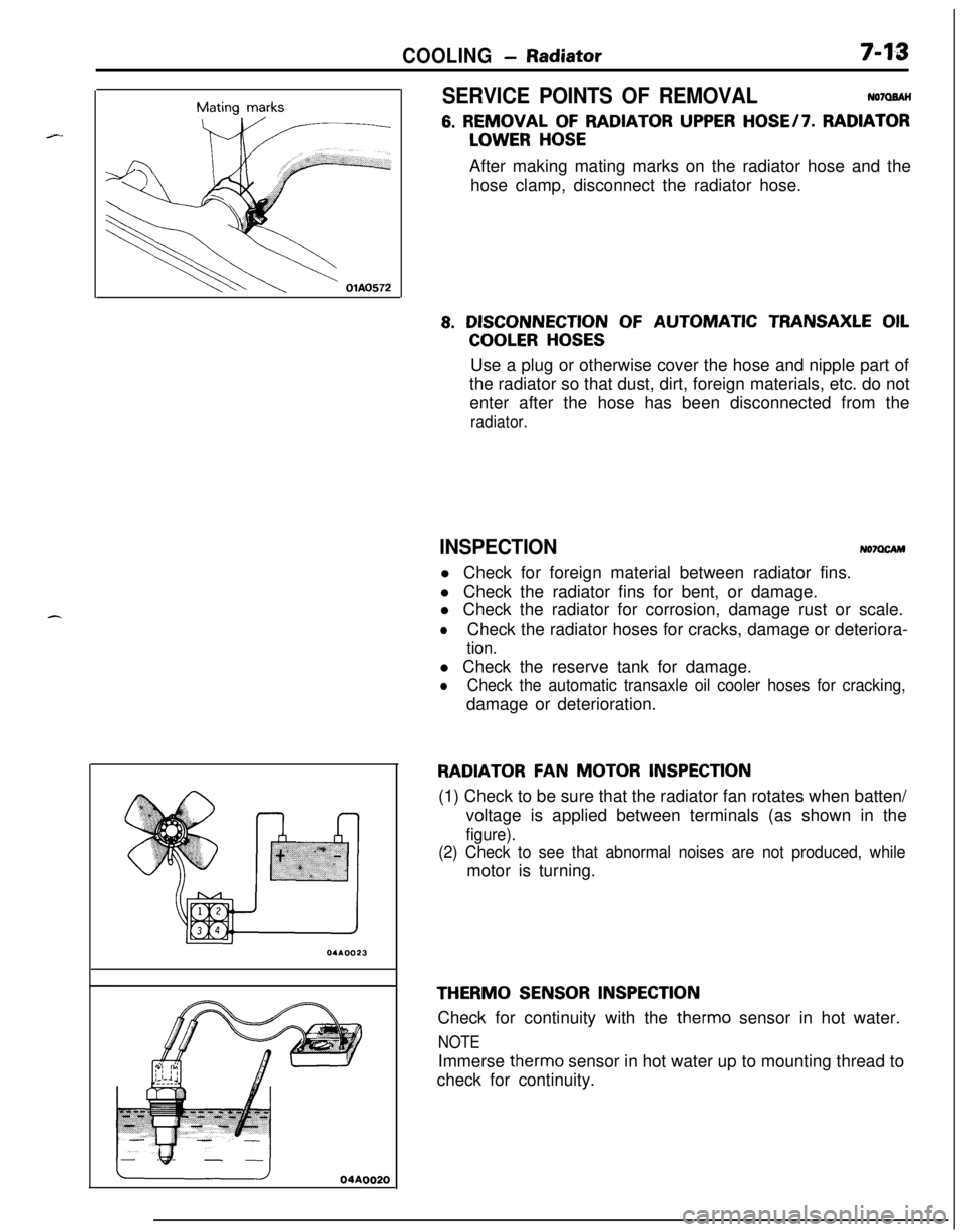
LOWER HOSEAfter making mating marks on the radiator hose and the
hose clamp, disconnect the radiator hose.
8. DISCONNECTION OF AUTOMATIC TRANSAXLE OIL
COOLER HOSESUse a plug or otherwise cover the hose and nipple part of
the radiator so that dust, dirt, foreign materials, etc. do not
enter after the hose has been disconnected from the
radiator.
INSPECTIONNo7OcAMl Check for foreign material between radiator fins.
l Check the radiator fins for bent, or damage.
l Check the radiator for corrosion, damage rust or scale.
lCheck the radiator hoses for cracks, damage or deteriora-
tion.l Check the reserve tank for damage.
lCheck the automatic transaxle oil cooler hoses for cracking,damage or deterioration.
RADIATOR FAN MOTOR INSPECTION(1) Check to be sure that the radiator fan rotates when batten/
voltage is applied between terminals (as shown in the
figure).
(2) Check to see that abnormal noises are not produced, whilemotor is turning.
THERM0 SENSOR INSPECTIONCheck for continuity with the therm0 sensor in hot water.
NOTEImmerse therm0 sensor in hot water up to mounting thread to
check for continuity.
Page 267 of 1216
COOLING - Water Pump <1.8L Engine>749SERVICE POINTS OF REMOVAL
NO’IMCAG
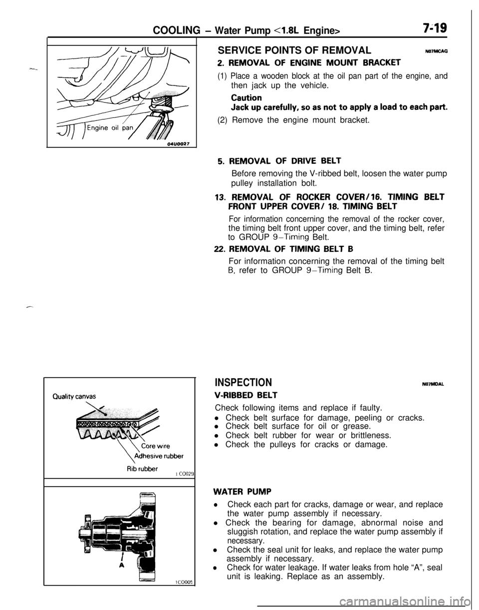
2. REMOVAL OF ENGINE MOUNT BRACKET
(1) Place a wooden block at the oil pan part of the engine, andthen jack up the vehicle.
Caution
Jack up carefully, so as not to apply a load to each part.(2) Remove the engine mount bracket.
\
\
Core wireAdhesive
rubber
Rib rubber1 coo21
5. REMOVAL OF DRIVE BELTBefore removing the V-ribbed belt, loosen the water pump
pulley installation bolt.
13. REMOVAL OF ROCKER COVER/16. TIMING BELT
FRONT UPPER COVER/ 18. TIMING BELT
For information concerning the removal of the rocker cover,the timing belt front upper cover, and the timing belt, refer
to GROUP
g-Timing Belt.
22. REMOVAL OF TIMING BELT BFor information concerning the removal of the timing belt
B, refer to GROUP g-Timing Belt B.
INSPECTIONN07MDAL
V-RIBBED BELTCheck following items and replace if faulty.
l Check belt surface for damage, peeling or cracks.
l Check belt surface for oil or grease.
l Check belt rubber for wear or brittleness.
l Check the pulleys for cracks or damage.
WATER PUMP
lCheck each part for cracks, damage or wear, and replace
the water pump assembly if necessary.
l Check the bearing for damage, abnormal noise and
sluggish rotation, and replace the water pump assembly if
necessary.lCheck the seal unit for leaks, and replace the water pump
assembly if necessary.
lCheck for water leakage. If water leaks from hole “A”, seal
unit is leaking. Replace as an assembly.
Page 268 of 1216

7-20COOLING - Water Pump <1.8L Engine>
aWater pump*<
l-----r,//
O-ringWater
pipe
04ROO24Identification
mark04lJoo25Alternater
brace
404uoo22
J
SERVICE POINTS OF INSTALLATIONN07ME40a
26. INSTALLATION OF O-RINGsInsert the O-ring to the water inlet pipe, and coat the,buter
circumference of the O-ring with water.,
By coating with water, the insertion to the water pump will
become easier.
Caution
1.Care must be taken not to permit engine oil or other
greases to adhere to the O-ring.
2.When inserting the pipe, check to be sure,that there
is no sand, dirt, etc. on its inner surface.
24. INSTALLATION OF WATER PUMP,
(1) Clean both gasket surfaces of water pump body and
cylinder block.
(2) Install new water pump gasket and water pump
assembly and tighten the bolts.
Bolt diameter (d)Torque
x length (e) mm (in.)Nm (ftlbs.)I
I I148 x 28 (.31 x 1.1)112-15 (9-10) 1
I I2
71 8 x 70 (.31 x 2.76) 120-27 (15-19)(
348x55(.31x2.17)12-15(9-10)
448x28(.31x1.1)I
22. INSTALLATION OF TIMING BELT B/20. FLANGE-For information concerning the installation of the timing
belt
B and the flange, refer to GROUP g-Timing Belt B.
18. INSTALLATION OF TIMING BELT/l7. TIMING BELT
FRONT LOWER COVER/lG. TIMING BELT FRONT UP-
PERCOVER/ 15. SEMI-CIRCULARPACKING / 13.
ROCKER COVERFor information concerning the installation of the timing
belt, the timing belt front lower cover, the timing belt front
upper cover, the semi-circular packing, and the rocker
cover, refer to GROUP
g-Timing Belt.
5. DRIVE BELT TENSION ADJUSTMENT
Refer to
P.7-9.
4. DRIVE BELT TENSION ADJUSTMENT
Refer to GROUP
19-Service Adjustment Procedures.
3. DRIVEBELTTENSIONADJUSTMENT
Refer to GROUP
24-Service Adjustment Procedures,
Page 270 of 1216
7-22COOLING - Water Pump <2.0L DOHC Engine>
20-27-Nm12-15 Nm14-20 ft.lbs.9- 11 ftlbs.\,/”
110-130 Nm@80-94 ftlbs. -04A0094
15. Crankshaft sprocketl a 16. Flange17. Timing belt B tensioner4e l + 18. Timing belt B19. Alternator bracel 4 20. Water pump21. Water pump gasketI)* 22. O-ring
NOTE(I) Reverse the removal procedures to reinstall.(2) 4* : Refer to “Service Points of Removal”.(3) ** : Refer to “Service Points of Installation”.(4) m : Non-reusable partsSERVICE POINTS OF REMOVAL
NO’IMCAH
2. REMOVAL OF ENGINE MOUNT BRACKET
(1) Place a wooden block at the oil pan part of the engine, and
then jack up the vehicle.
Cautioncylb
Jack up carefully, so as not to apply a load to each part..__
(2) Remove the engine mount bracket.