Page 271 of 1216

COOLING - Water Pump <2.0L DOHC Engine>7-2’3
12. REMOVAL OF AUTOMATIC TENSIONERI14. TIMING
BELTFor information concerning removal of the automatic
tensioner and the timing belt, refer to GROUP
g-Timing
Belt.
18. REMOVAL OF TIMING BELT BFor information concerning the removal of timing belt
6,refer to GROUP
g-Timing Belt B.Quality
canvas
\
\
Core wireAdhesive
rubber
Rib rubberlCOO2I
MRM2.
INSPECTION
V-RIBBED BELT
No7mDA.lCheck following items and replace if faulty.
l Check belt surface for damage, peeling or cracks.
l Check belt surface for oil or grease.
l Check belt rubber for wear or brittleness.
‘0 Check the pulleys for cracks or damage.
WATER PUMP
lCheck each part for cracks, damage or wear, and replace
the water pump assembly if necessary.
l Check the bearing for damage, abnormal noise and
sluggish rotation, and replace the water pump assembly if
necessary.
lCheck the seal unit for leaks, and replace the water pump
assembly if necessary.
l Check for water leakage.
SERVICE POINTS OF INSTALLATION
N07MEAN
22. INSTALLATION OF O-RING
Insert the O-ring to the water inlet pipe, and coat the outer
circumference of the O-ring with water.
By coating with water, the insertion to the water pump will
become easier.
Caution
1. Care must be taken not to permit engine oil or other
greases to adhere to the O-ring.
2. When inserting the pipe, check to be sure that there
is no sand, dirt, etc. on its inner surface.
Page 273 of 1216
COOLING - Water Hose and Water Pipe <1.8L Engine>
WATER HOSE AND WATER PIPE
<1.8L Engine>
_-REMOVAL AND INSTALLATIONNO’IIA-A27-33 Nm
20-24 ftlbs.
12-15 Nms- 11 ft.lbs.Removal steps
1 Air intake hose
2. Engine oil level gauge guide3. O-ring
4. Self locking nut
5. Gasket
6. Oxygen sensor harness connector
7. Exhaust manifold cover (A)
8. Engine hanger9. Exhaust manifold
IO. Exhaust manifold gasket
11. Exhaust manifold cover(B)NOTE(1) Reverse the removal procedures to reinstall.(2) m : Non-reusable parts
Page 275 of 1216
COOLING - Water Hose and Water Pipe <1.8L Engine>7-27
r
L
0410024
Mating marksSERVICE POINTS OF INSTALLATIONNO7lDAJl
17. INSTALLATION OF 0-l?ING/lG. WATER INLET PIPE
Insert the O-ring to the water inlet pipe, and coat the outer
circumference of the O-ring with water.
By coating with water, the insertion to the water pump will
become easier.
Caution
Care must be taken not to permit engine oil or other
greases to adhere to the O-ring.
15. CONNECTION OF RADIATOR LOWER HOSEAlign the mating marks on the radiator hose and hose
clamp and then connect them; then, applying force in the
direction indicated by the arrow in the illustration, seat the
clamp to the trace marks of the previous connection.
Caution
Be sure to install the hose clamps at the trace marks of
the previous connection.
Page 278 of 1216
7-30COOLING - waterHose and Water Piue <2.0L DOHC Ermine (Non-Turbo)>
04ROO24
04AOO98SERVICE POINTS OF INSTALLATION
N071DAJZ
17. INSTALLATION OF O-RING/ 16. WATER INLET PIPE“4Insert the O-ring to the water inlet pipe, and coat the outer
circumference of the O-ring with water.
By coating with water, the insertion to the water pump will
become easier.Caution
Care must be taken not to permit engine oil or other
greases to adhere to the O-ring
15. CONNECTION OF RADIATOR LOWER HOSEAlign the mating marks on the radiator hose and hose
clamp and then connect them; then, applying force in the
direction indicated by the arrow in the illustration, seat the
clamp to the trace marks of the previous connection.Caution
Be sure to install the hose clamps at the trace marks ofthe
previous connection.
Page 279 of 1216

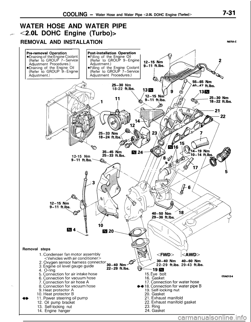
COOLING -Water Hose and Water Pipe <2.0L DOHC Engine (Turbo)>7-31WATER HOSE AND WATER PIPE
7--<2.0L DOHC Engine (Turbo)>
REMOVAL AND INSTALLATION
N071A-C
. .
ation OperationPost-installi@Filling of the Engine Oil(Refer to GROUP g-EngineaFilling of the
Engine Coolant(Refer to GROUP 7-ServiceAdjustment Procedures.)
Pre-removal OperationeDraining of the Engine Coolant(Refer to GROUP 7-ServiceAdjustment Procedures.)*Draining of the Engine Oil(Refer to GROUP g-Engine
25-30 Nm
18-22 ftlbs.4n-47 ft.lbs.
w35-45 N/m12-15 Nm25-33 ft.lbs.
9- 11ft.lbs.----Q&Removal steps
1. Condenser fan motor assembly2. Oxygen sensor harness connector3. Engine oil level gauge guide4. O-ring5. Connection for air intake hose6. Connection for vacuum hose7. Connection for air hose A8. Connection for vacuum hose9. Heat protector A10. Heat protector B
4*11. Power steering oil pump
12. Oil pump bracket
13. Self-locking nut
14. Engine hanger22-29
ft.lbs. 29-43 ft.lbs.
15. Eye bolt16. Gasket17. Connection for water hose
I)+ 18. Connection for water pipe B19. Self-locking nut20. Gasket21. Exhaust manifold22. Exhaust manifold gasket
23. Ring
24. Gasket
05m154
Page 280 of 1216
7-32COOLING -Water Hose and Water Pipe <2.0L DOHC Engine (Turbo)>
35-50 Nm/ 25-36 ft.lbs.
35-50 Nm-- - _ . __._25-36 ft.lbs.25. Oil return pipe
26.Gasket
++ l 27. Turbocharger
28.Eye bolt29.Gasket
30.Water pipe631.Eye bolt32.Gasket33. Water pipe A
++ 34. Water hose (to turbocharger)35. Water hose
36. Water by-pass hose37. Connection for heater hose
+e l 38. Connection for radiator lower hose39. Water hose
40. Water hose
41. Water hose
22-30 ft.lbs.30-40 Nm
22-29 ft.lbs.04A011642. Exhaust pipe support bracket
43. Water pipe
l * 44. Water inlet pipe
l * 45. O-ring
FFTkeverse the removal procedures to reinstall.(2) a+ : Refer to “Service Points of Removal”.(3) l + : Refer to “Service Points of Installation”(4) m : Non-reusable parts
Page 281 of 1216

COOLING- Water Hose and Water Pipe <2.0L DOHC Engine (Turbo)>7-330140552
Mating marks
04A0090
rMating marks
04A0090
SERVICE POINTS OF REMOVALNO7lBAC311. DISCONNECTION OF POWER STEERING OIL PUMP
Disconnect the oil pump with hoses from the bracket.
NOTEThe removed power steering oil pump should be fastened
(by using rope, etc.) in a position that will not interfere with
the removal/installation of the engine assembly.
27. REMOVAL OF TURBOCHARGER ASSEMBLY
Remove the turbocharger assembly with the exhaust
fitting, water pipe A, water pipe
B and the oil pipe attached
to it.
38. DISCONNECTION OF RADIATOR LOWER HOSE
After making mating marks on the radiator hose and the
hose clamp, disconnect the radiator hose.
INSPECTIONN07lCAAa3WATER PIPE AND HOSE INSPECTION
Check the water pipe and hose for cracks, damage, clog and
replace them if necessary.
SERVICE POINTS OF INSTALLATION
N071DAJ345. INSTALLATION OF
0-RING/44. WATER INLET PIPE
Insert the O-ring to the water inlet pipe, and coat the outer
circumference of the O-ring with water.
By coating with water, the insertion to the water pump will
become easier.
Caution
Care must be taken not to permit engine oil or other
greases to adhere to the O-ring.
38. CONNECTION OF RADIATOR LOWER HOSE
Align the mating marks on the radiator hose and hose
clamp and then connect them; then, applying force in the
direction indicated by the arrow in the illustration, seat the
clamp to the trace marks of the previous connection.
Caution
Be sure to install the hose clamps at the trace marks ofthe previous connection.
Page 282 of 1216

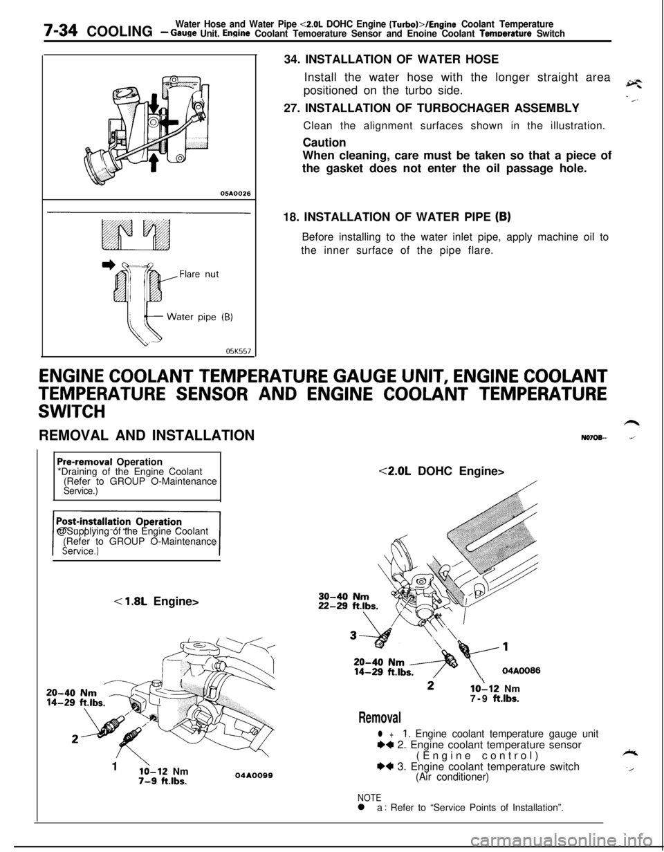
7-34 COOLINGWater Hose and Water Pipe <2.0L DOHC Engine (Turbo)>/Engine Coolant Temperature- Gauge Unit. Engine Coolant Temoerature Sensor and Enoine Coolant Temoerature Switch
05A0026
05K55734. INSTALLATION OF WATER HOSE
Install the water hose with the longer straight area
positioned on the turbo side.
27. INSTALLATION OF TURBOCHAGER ASSEMBLY
Clean the alignment surfaces shown in the illustration.
Caution
When cleaning, care must be taken so that a piece of
the gasket does not enter the oil passage hole.
18. INSTALLATION OF WATER PIPE
(B)Before installing to the water inlet pipe, apply machine oil to
the inner surface of the pipe flare.
ENGINE COOLANT TEMPERATURE GAUGE UNIT, ENGINE COOLANT
TEMPERATURE SENSOR AND ENGINE COOLANT TEMPERATURE
SWITCHREMOVAL AND INSTALLATION
N070%-
Pre-removal Operation
*Draining of the Engine Coolant
(Refer to GROUP O-Maintenance
Service.)@Supplying of the Engine Coolant
(Refer to GROUP O-Maintenance
< 1.8L Engine>
20-4014-291
’lo-12 Nm7-9 ft.lbs.04AOO99<2.0L DOHC Engine>10112 Nm
7-9 ft.lbs.
Removal
l +1. Engine coolant temperature gauge unit
++ 2. Engine coolant temperature sensor
(Engine control)
*4 3. Engine coolant temperature switch(Air conditioner)
NOTEl a : Refer to “Service Points of Installation”.