Page 1002 of 1216
21-308 AUTOMATIC TRANSAXLE - Rear Clutch Assembly
@
/
(
TFAO240SERVICE POINTS OF
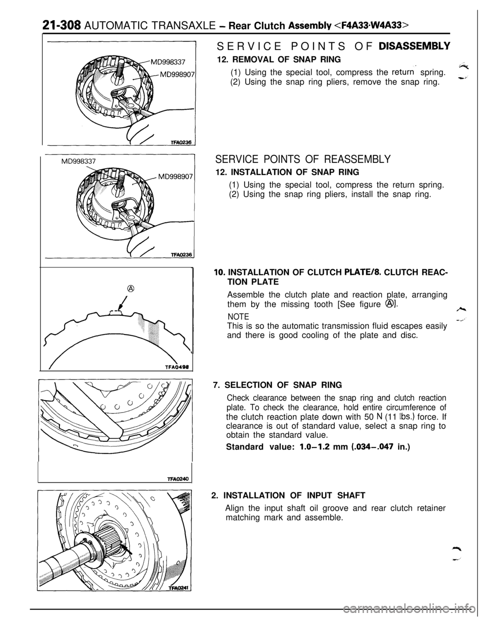
DISASSEM.BLY12. REMOVAL OF SNAP RING
(1) Using the special tool, compress the
returns spring.
(2) Using the snap ring pliers, remove the snap ring.
SERVICE POINTS OF REASSEMBLY12. INSTALLATION OF SNAP RING
(1) Using the special tool, compress the return spring.
(2) Using the snap ring pliers, install the snap ring.
10. INSTALLATION OF CLUTCH PLATE/*. CLUTCH REAC-
TION PLATE
Assemble the clutch plate and reaction plate, arranging
them by the missing tooth [See figure
@I.
NOTEThis is so the automatic transmission fluid escapes easily
and there is good cooling of the plate and disc.
7. SELECTION OF SNAP RING
Check clearance between the snap ring and clutch reaction
plate. To check the clearance, hold entire circumference ofthe clutch reaction plate down with 50
N (11 Ibs.) force. If
clearance is out of standard value, select a snap ring to
obtain the standard value.
Standard value:
1.0-1.2 mm (.034-.047 in.)
2. INSTALLATION OF INPUT SHAFT
Align the input shaft oil groove and rear clutch retainer
matching mark and assemble.
Page 1157 of 1216
HEATERS AND AIR CONDITIONING - Service Adjustment Procedures 249*I3
--Air-therm0
sensor
Air inlet
sensor
E>aporator(3)
Set the gauge manifold in place and check whether or not
the pressure at the high-pressure side has become the
dual-pressure switch activation pressure.
(4) Replace the switch if, under ordinary conditions, there is no
continuity.Caution
The condition can be considered to be satisfactory if
there is continuity.
Never increase the pressure in a deliberate attempt to
obtain an abnormally high temperature, because to do
so risks blowing the compressor relief valve.AIR-THERM0 SENSOR AND AIR-INLET SENSOR
If frost forms on the surfaces of the evaporator fins, the cause
might be a malfunction of
air-therm0 sensor.
The temperature of the air-flowing from the evaporator’s outlet
is sensed by the thermistor, and the signals conveying this dataare input to the air conditioner control unit, thus switching the
compressor’s clutch ON or OFF.
This functions when the evaporator’s air-flow is low, or the
evaporator’s fins are clogged by dust, etc., or when the amountof refrigerant is insufficient.
These sensors detect the temperature within the passenger
compartment and the temperature at the cooling unit inlet,
thus causing changes of the resistance value, and this data is
provided to the air conditioner control unit as input.
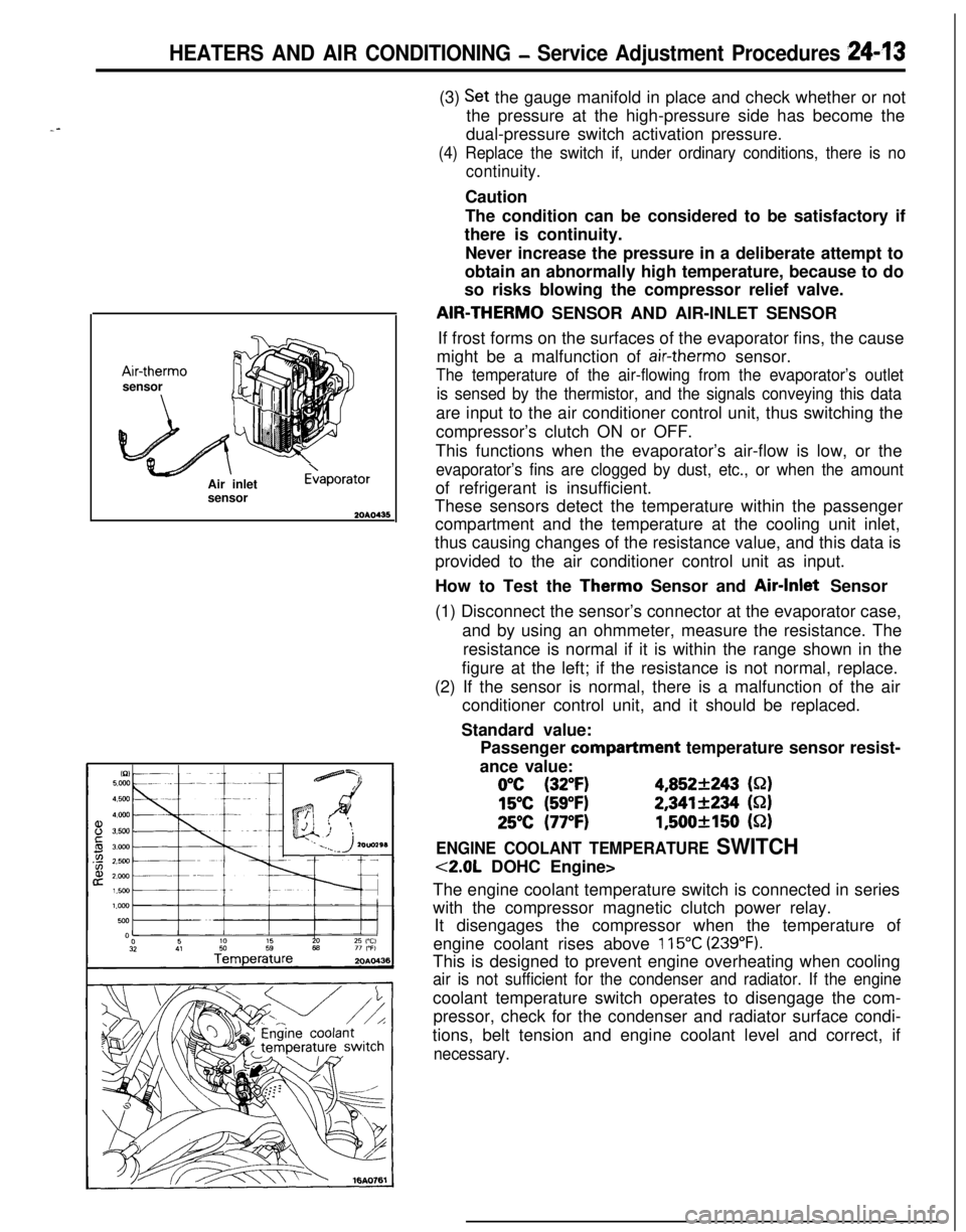
How to Test the Therm0 Sensor and Air-Inlet Sensor
(1) Disconnect the sensor’s connector at the evaporator case,
and by using an ohmmeter, measure the resistance. The
resistance is normal if it is within the range shown in the
figure at the left; if the resistance is not normal, replace.
(2) If the sensor is normal, there is a malfunction of the air
conditioner control unit, and it should be replaced.
Standard value:
Passenger compartment temperature sensor resist-
ance value:
0°C (32°F)4,852+243 (S-2)
15°C (59°F)2,341+234 (S-2)
25°C (77°F)1,500+150 (52)
ENGINE COOLANT TEMPERATURE SWITCH
<2.0L DOHC Engine>
The engine coolant temperature switch is connected in series
with the compressor magnetic clutch power relay.
It disengages the compressor when the temperature of
engine coolant rises above
115°C (239°F).This is designed to prevent engine overheating when cooling
air is not sufficient for the condenser and radiator. If the enginecoolant temperature switch operates to disengage the com-
pressor, check for the condenser and radiator surface condi-
tions, belt tension and engine coolant level and correct, if
necessary.
Page 1160 of 1216
24-16 HEATERS AND AIR CONDITIONING - Service Adjustment Procedures
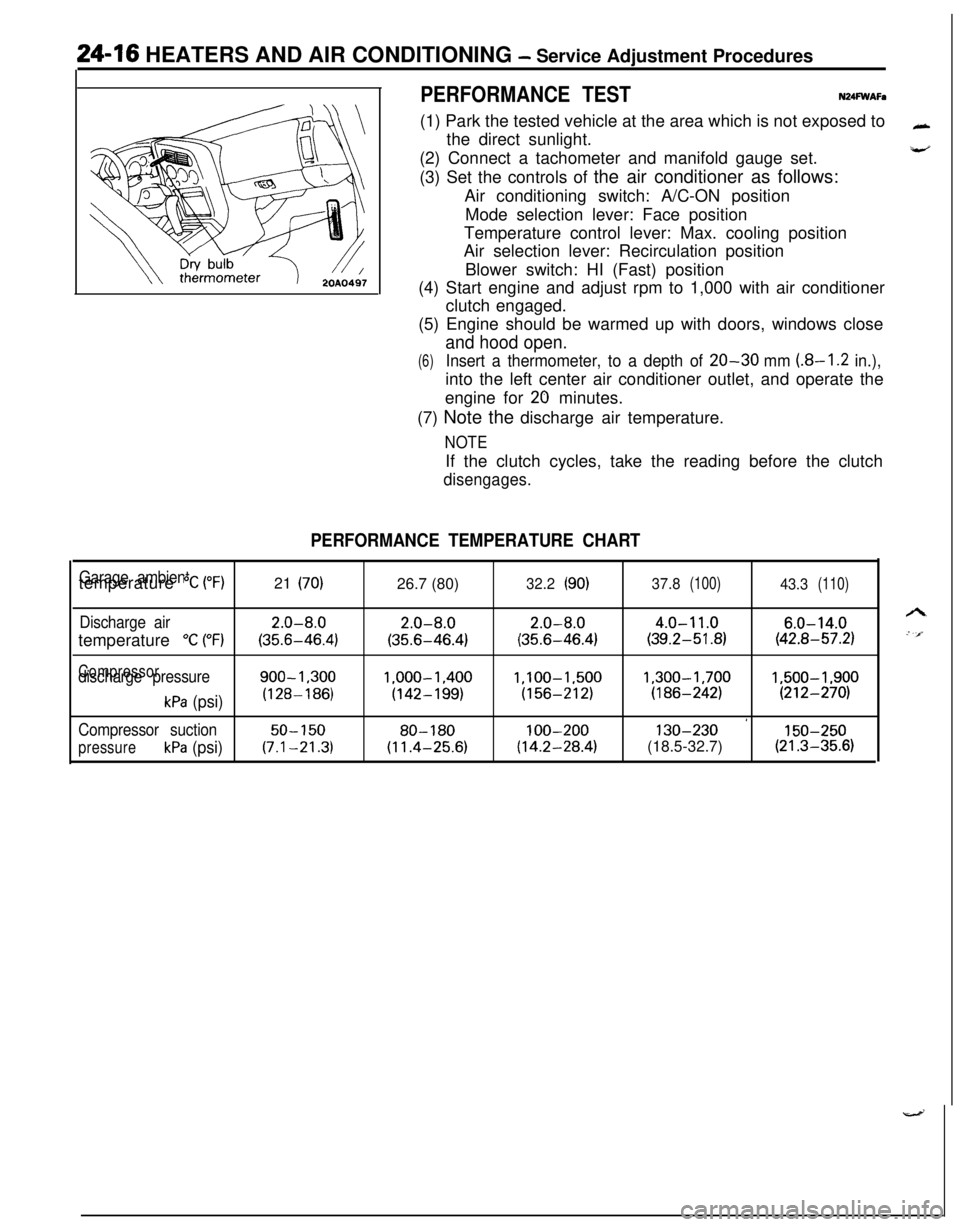
PERFORMANCE TESTN24FWAFa(1) Park the tested vehicle at the area which is not exposed to
the direct sunlight.
(2) Connect a tachometer and manifold gauge set.
(3) Set the controls of the air conditioner as follows:
Air conditioning switch: A/C-ON position
Mode selection lever: Face position
Temperature control lever: Max. cooling position
Air selection lever: Recirculation position
Blower switch: HI (Fast) position
(4) Start engine and adjust rpm to 1,000 with air conditioner
clutch engaged.
(5) Engine should be warmed up with doors, windows close
and hood open.
(6)Insert a thermometer, to a depth of 20-30 mm (8-I .2 in.),into the left center air conditioner outlet, and operate the
engine for
20 minutes.
(7) Note the discharge air temperature.
NOTEIf the clutch cycles, take the reading before the clutch
disengages.
PERFORMANCE TEMPERATURE CHART
Garage ambienttemperature “C (“F)21 (70)26.7 (80)32.2(90)37.8(100)43.3(110)
Discharge air2.0-8.02.0-8.02.0-8.04.0-11.06.0-14.0temperature
“C (“F)(35.6-46.4)(35.6-46.4)(35.6-46.4)(39.2-51.8)(42.8-57.2)
Compressordischarge pressure900-1.3001.000-1.400l,lOO-1,5001,300-1,7001,500-1,900
kPa (psi)(128-186)(142-199)(156-212)(186-242)(212-270)
’Compressor suction50-15080-180100-200130-230150-250
pressurekPa (psi)(7.1-21.3)(11.4-25.6)(14.2-28.4)(18.5-32.7)(21.3-35.6)
Page 1169 of 1216
HEATERS AND AIR CONDITIONING - Service Adjustment Procedures 24-25
16A1077
20AO499
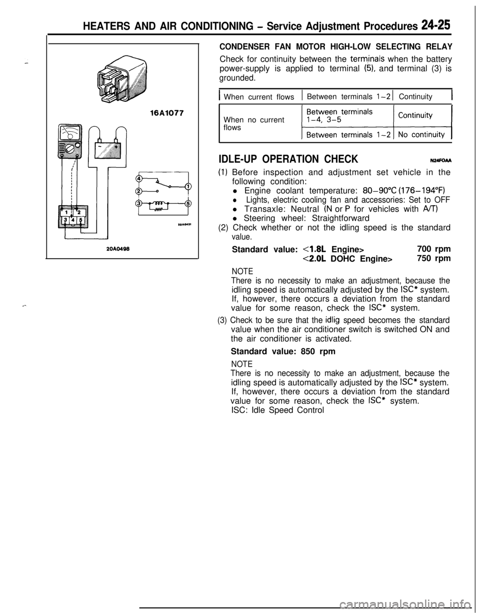
CONDENSER FAN MOTOR HIGH-LOW SELECTING RELAYCheck for continuity between the
term,inals when the battery
power-supply is applied to terminal
(5), and terminal (3) is
grounded.
IWhen current flows1 Between terminals l-2 1 Continuity1When no current
flows
IDLE-UP OPERATION CHECKN24FoAA
(I) Before inspection and adjustment set vehicle in the
following condition:
l Engine coolant temperature:
80-90°C (176-194°F)
lLights, electric cooling fan and accessories: Set to OFFl Transaxle: Neutral
(N or P for vehicles with A/T)l Steering wheel: Straightforward
(2) Check whether or not the idling speed is the standard
value.Standard value:
4.8L Engine>700 rpm
<2.0L DOHC Engine>750 rpm
NOTE
There is no necessity to make an adjustment, because theidling speed is automatically adjusted by the
ISC” system.
If, however, there occurs a deviation from the standard
value for some reason, check the
ISC” system.
(3) Check to be sure that the idlig speed becomes the standardvalue when the air conditioner switch is switched ON and
the air conditioner is activated.
Standard value: 850 rpm
NOTE
There is no necessity to make an adjustment, because theidling speed is automatically adjusted by the
ISC” system.
If, however, there occurs a deviation from the standard
value for some reason, check the
ISC” system.
ISC: Idle Speed Control
Page 1183 of 1216
HEATERS AND AIR CONDITIONING - Compressor24-39
\/20A0400
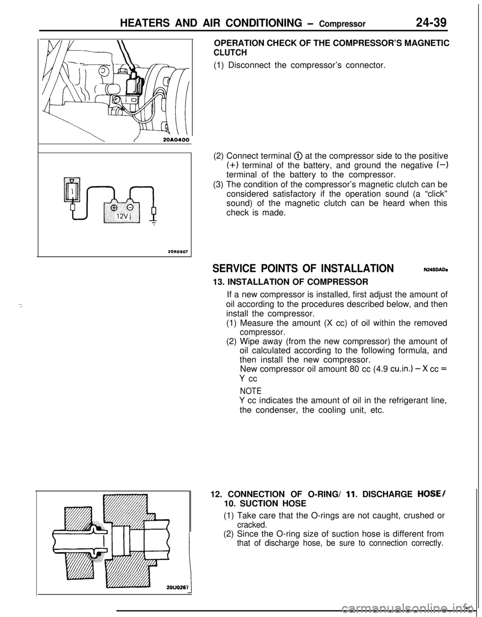
20R0507OPERATION CHECK OF THE COMPRESSOR’S MAGNETIC
CLUTCH(1) Disconnect the compressor’s connector.
(2) Connect terminal
@ at the compressor side to the positive(+) terminal of the battery, and ground the negative
(-)terminal of the battery to the compressor.
(3) The condition of the compressor’s magnetic clutch can be
considered satisfactory if the operation sound (a “click”
sound) of the magnetic clutch can be heard when this
check is made.
SERVICE POINTS OF INSTALLATIONN248DADa13. INSTALLATION OF COMPRESSOR
If a new compressor is installed, first adjust the amount of
oil according to the procedures described below, and then
install the compressor.
(1) Measure the amount (X cc) of oil within the removed
compressor.(2) Wipe away (from the new compressor) the amount of
oil calculated according to the following formula, and
then install the new compressor.
New compressor oil amount 80 cc (4.9
cu.in.) - X cc =
Y cc
NOTE
Y cc indicates the amount of oil in the refrigerant line,
the condenser, the cooling unit, etc.
12. CONNECTION OF O-RING/
11. DISCHARGE HOSE/
10. SUCTION HOSE
(1) Take care that the O-rings are not caught, crushed or
cracked.(2) Since the O-ring size of suction hose is different from
that of discharge hose, be sure to connection correctly.
1t
/