Page 978 of 1216

21-284 AUTOMATIC TRANSAXLE - Transaxle Assemblv
//TFAOlSO
TFA0167
Outph bearing retainerTFAOl4916. Install the transfer shaft .
17. Position solder approx.
10 mm. (.40 in,) in length and 1.6
mm
(06 in.) in diameter in the output bearing retainer as
shown in the figure and then install the outer race.
18. Install the output bearing retainer and tighten the bolts withthe specified torque.
Output bearing retainer mounting bolts:
20-27 Nm (15-19 ft.lbs.) ,+19. Loosen the bolts and remove the output bearing retainer.--
20. Remove the outer race from the output bearing retainer
and remove the solder. If the solder does not break,
perform the work in steps
17-20 with large diameter
solder. Measure the thickness of the crushed solder with a
micrometer and select a spacer with the correct thickness
so that the pre-load reaches the standard value.
Standard value:
0.075-0.135 mm (.0030--0053 in.)
21. Install the spacer and the outer race selected in the
previous step in the output bearing retainer.
22. Install a new O-ring in the outer circumference of the
output bearing retainer.
23. Apply ATF to the O-ring, install the output bearing retainer
and tighten the bolts with the specified torque.
Output bearing retainer mounting bolts:
20-27 Nm (15-19 ft.lbs.) -
-
Page 988 of 1216

21-294 AUTOMATIC TRANSAXLE - Transaxle Assemblv
‘/TFAOl16
TFA0590-64. Position solder approximately
10 mm (39 in.) in length and
1.6 mm (06 in.) in diameter in the bearing outer race in theposition shown in the figure
.
65. Position solder approximately
10 mm (39 in.) in length and
1.6 mm
(.06 in.) in diameter in the differential rear bearing
retainer in the position shown in the figure and then install
the outer race .
66. Install the differential rear bearing retainer and tighten the
bolts with the specified torque.
Differential rear bearing retainer mounting bolts:
30-40 Nm (22-28 ft.lbs.167. Loosen the bolts, remove the differential rear bearing
retainer and then remove the solder. If the solder does not
crush, perform the work in steps 64-68 with large
diameter solder.
68. Measure the thickness of the crushed solder with a
micrometer and then select and install a spacer so the endplay and pre-load reach the standard value.
Standard value
Front differential case end play:
0.045-0.165 mm (.0017-.0064 in.)
Front differential case preload:
0.075-0.135 mm (.0030-.0053 in.)
69. Install a new O-ring in the differential rear bearing retainer,
apply ATF and then install in the transaxle case. Tighten thebolts with the specified torque.
Differential rear bearing retainer mounting bolts:
30-40 Nm (22-28 ft.lbs.)
Page 1098 of 1216

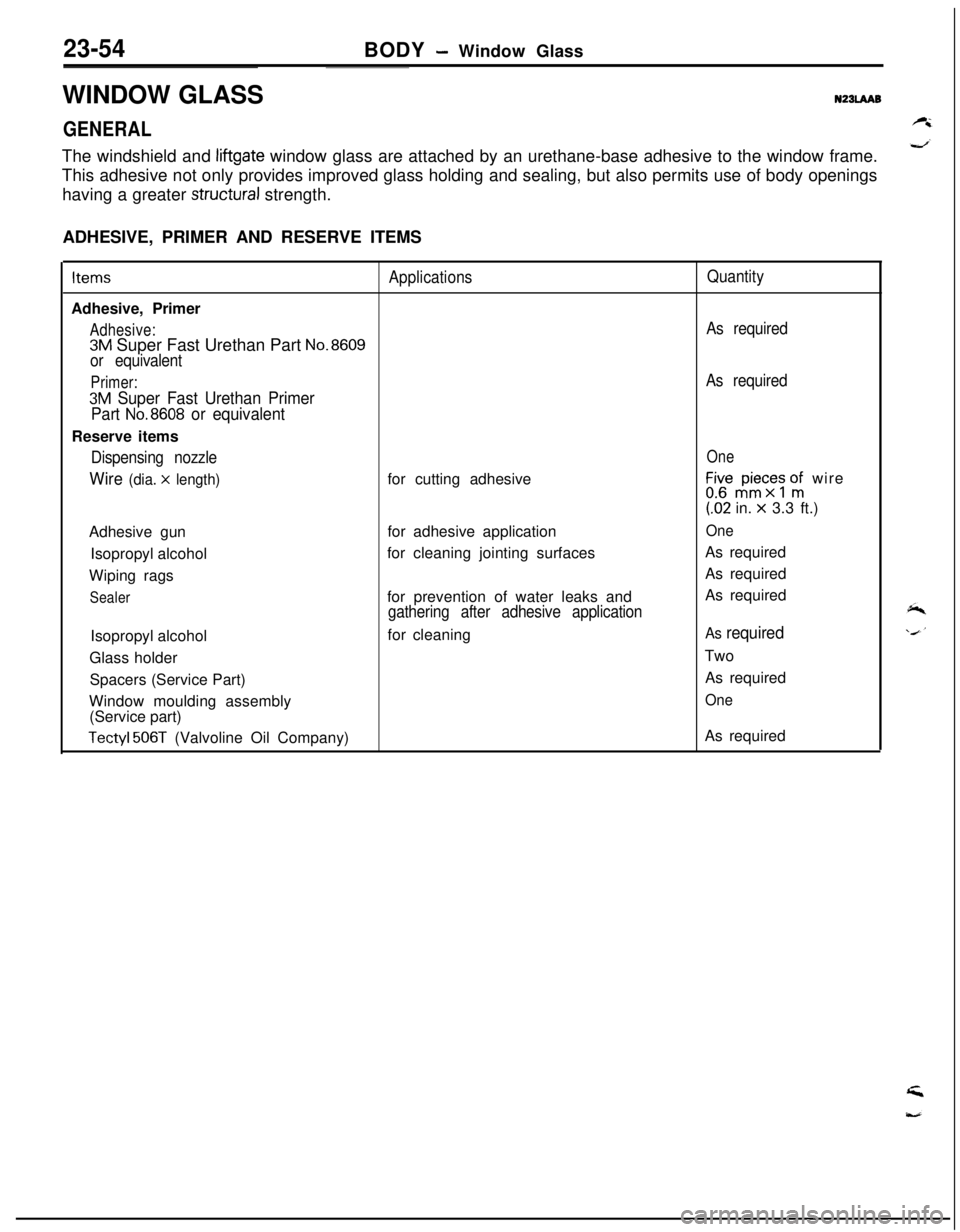
23-54BODY - Window Glass
WINDOW GLASS
N23LAAB
GENERALThe windshield and
liftgate window glass are attached by an urethane-base adhesive to the window frame.
This adhesive not only provides improved glass holding and sealing, but also permits use of body openings
having a greater
structural strength.
ADHESIVE, PRIMER AND RESERVE ITEMSItems
ApplicationsQuantityAdhesive, Primer
Adhesive:As required
3M Super Fast Urethan Part No.8609
or equivalent
Primer:As required
3M Super Fast Urethan Primer
Part
No.8608 or equivalentReserve items
Dispensing nozzleOne
Wire (dia. x length)for cutting adhesiveLir,“$c;s onfi wire(62 in.
x 3.3 ft.)
Adhesive gunfor adhesive application
OneIsopropyl alcoholfor cleaning jointing surfacesAs required
Wiping ragsAs required
Sealerfor prevention of water leaks andAs requiredgathering after adhesive applicationIsopropyl alcoholfor cleaning
As requiredGlass holderTwo
Spacers (Service Part)As required
Window moulding assembly
One(Service part)
Tectyl 506T (Valvoline Oil Company)As required
Page 1123 of 1216

23-78BODY -Instrument Panel23-79
INSTRUMENT PANELNZBUAAPI_-
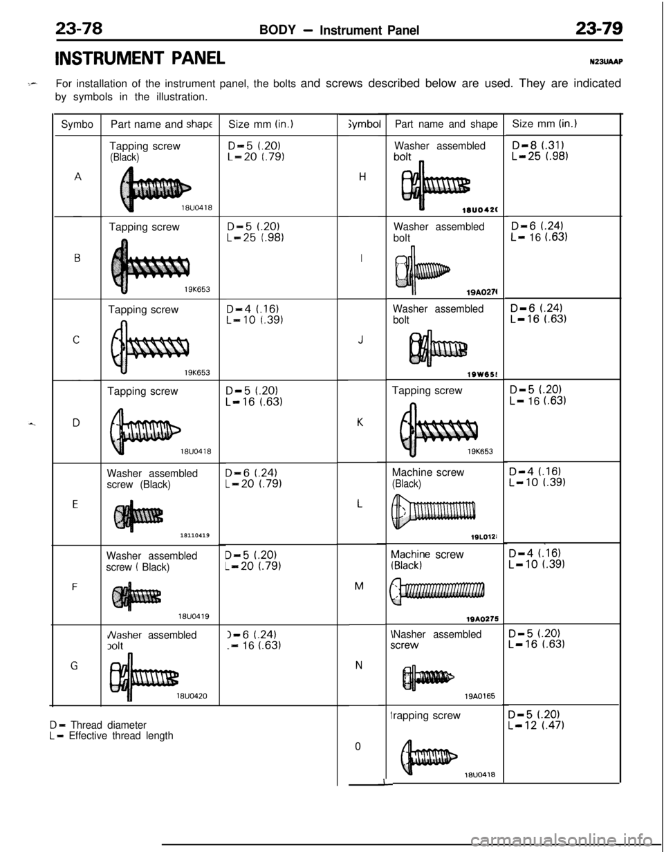
For installation of the instrument panel, the bolts and screws described below are used. They are indicated
by symbols in the illustration.
Symbo
E
F
GPart name and
shapeTapping screw
(Black)Tapping screw
Tapping screw
19K653Tapping screw
Washer assembled
screw (Black)18110419
Washer assembled
screw
! Black)
18UO419
Nasher assembled
3olt
8UO420
D - Thread diameterL = Effective thread lengthSize mm
(in.)
D-5 t.20)L-20 f.79)
D-5 1.20)
L-25 t.98)
D-4 t.16)L-10 r.391
D-5 f.20)
L-16 l.63)
D-6 t.24)
L-20 l.79)
D-5 t.20)
L-20 t.791
I-6 t.24)-=- 16 i.63);ymbo
H
I
J
K
L
M
N0
~a2h$e screw
WA0275
Nasher assembledicrew\I
1
-I-rapping screw
Part name and shape
Washer assembled
lOUO42(
Washer assembled
bolt
19A0274
Washer assembled
bolt
lSW65!Tapping screw
653Machine screw
(Black)
19A0165
18UO418Size mm
(in.)
D-8 l.31)L-25 t.98)
D-6 t.24)
L- 16 (.63)
D-6 f.24)L-16 l.63)
D-5 (.20)
L- 16 i.631
D-4 t.16)L-10 l.39)
D-4 (.‘16)
L-10 t.391
D-5 t.20)L-16 l.63)
D-5 l.20)L-12 t.471
Page 1141 of 1216

BODY - Seat Belt23-97
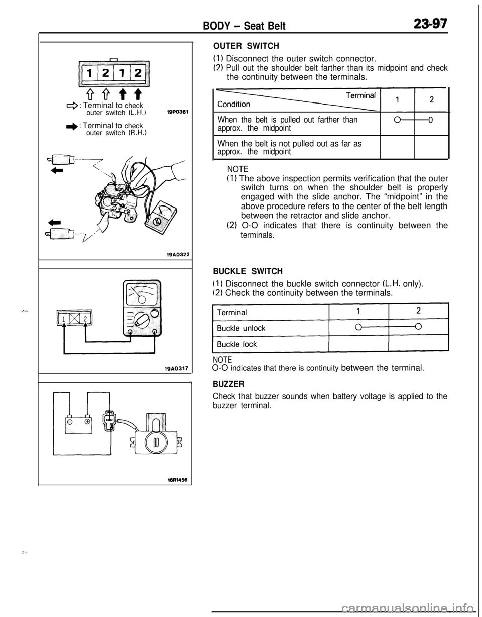
4 : Terminal to check
outer switch IL.H.1
+ : Terminal to check
outer switch (R.H.1
lQPO36119A0322lQA0317
OUTER SWITCH
(1) Disconnect the outer switch connector.
(2) Pull out the shoulder belt farther than its midpoint and checkthe continuity between the terminals.
When the belt is pulled out farther than
approx. the midpoint00
When the belt is not pulled out as far as
approx. the midpoint
NOTE
(1) The above inspection permits verification that the outer
switch turns on when the shoulder belt is properly
engaged with the slide anchor. The “midpoint” in the
above procedure refers to the center of the belt length
between the retractor and slide anchor.
(2) O-O indicates that there is continuity between the
terminals.
BUCKLE SWITCH
(1) Disconnect the buckle switch connector (L.H. only).
(2) Check the continuity between the terminals.
)I
NOTEO-O indicates that there is continuity between the terminal.
BUZZER
Check that buzzer sounds when battery voltage is applied to the
buzzer terminal.
i