1991 MITSUBISHI ECLIPSE length
[x] Cancel search: lengthPage 339 of 1216
ENGINE - Cylinder Head and Valve9-55
3EN026
w -w===j=Margin , EN034
Squareness
IFree length
INSPECTION
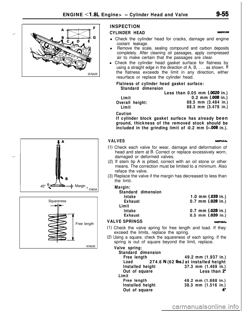
CYLINDER HEADNosocAMl Check the cylinder head for cracks, damage and engine
coolant leakage.l
Remove the scale, sealing compound and carbon deposits
completely. After cleaning oil passages, apply compressedair to make certain that the passages are clear.
l Check the cylinder head gasket surface for flatness by
using a straight edge in the direction of A, B, . . . as shown. Ifthe flatness exceeds the limit in any direction, either
resurface or replace the cylinder head.
Flatness of cylinder head gasket surface:
Standard dimension
Limit
Overall height:
Limit
Caution
Less than 0.05 mm (0020 in.)
0.2 mm (008 in.)
88.5 mm (3.484 in.)
88.3 mm (3.478 in.)
If cylinder block gasket surface has already been
ground, thickness of the removed stock should be
included in the grinding limit of -0.2 mm
(-,008 in.).
VALVESNo9PGMa
(1) Check each valve for wear, damage and deformation of
head and stem at
B. Correct or replace excessively worn,
damaged or deformed valves.
(2) If stem tip A is pitted, correct with an oil stone or other
means. The correction must be limited to a minimum. Also
reface the valve.
(3) Replace the valve if the margin has decreased to less than
the limit.
Margin:
Standard dimension
Intake1.0 mm (.039 in.)
Exhaust0.7 mm (028 in.)
Limit
Intake0.7 mm (.028 in.)
Exhaust0.5 mm LO20 in.)
VALVE SPRINGSNOWGh
(1) Check the valve spring for free length and load. If they
exceed the limits, replace the spring.
(2) Using a square, check the squareness of each spring. If thespring is out of square beyond the limit, replace.
Valve spring:
Standard dimension
Free length
49.2 mm (1.937 in.)
Load274.6 N (62 Ibs.) at installed height
Installed height37.3 mm (1.469 in.)
Out of square
Less than 2”
Limit
Free length48.2 mm (1.888 in.)
Installed height38.3 mm (1.516 in.)
Out of square4”
Page 347 of 1216
ENGINE <1.8L Engine> -Front Case, Oil Pump and Silent Shaft9-63
aSocket wrench/
3EN271
MD998285R
Fasten toqether with
the timtins under cover
C
belt tensioner3ENOOWTiming marks
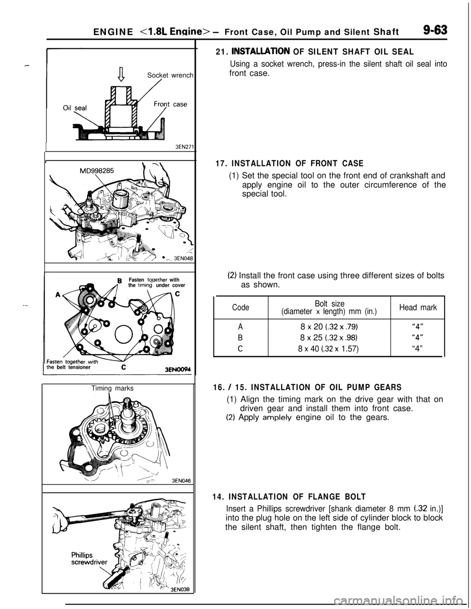
16. / 15. INSTALLATION OF OIL PUMP GEARS(1) Align the timing mark on the drive gear with that on
driven gear and install them into front case.
(2) Apply amplely engine oil to the gears.
3EN046
21. INSTALLATlON OF SILENT SHAFT OIL SEAL
Using a socket wrench, press-in the silent shaft oil seal intofront case.
17. INSTALLATION OF FRONT CASE(1) Set the special tool on the front end of crankshaft and
apply engine oil to the outer circumference of the
special tool.
(2) Install the front case using three different sizes of bolts
as shown.
Code
A
B
C
Bolt size
(diameter x length) mm (in.)8
x 20 (.32 x .79)8
x 25 (.32 x .98)
8 x 40 (32 x 1.57)
Head mark
“4”
“4”“4”
14. INSTALLATION OF FLANGE BOLT
Insert a Phillips screwdriver [shank diameter 8 mm (32 in.)]into the plug hole on the left side of cylinder block to block
the silent shaft, then tighten the flange bolt.
Page 354 of 1216
ENGINE <1.8L Engine> -Crankshaft, Flywheel and Drive Plate
3EN055
6EN043
1 EN067
MAIN BEARINGS AND CONNECTING ROD BEARINGSVisually inspect each bearing for peeling, melt, seizure and
improper contact. Replace the faulty bearings.
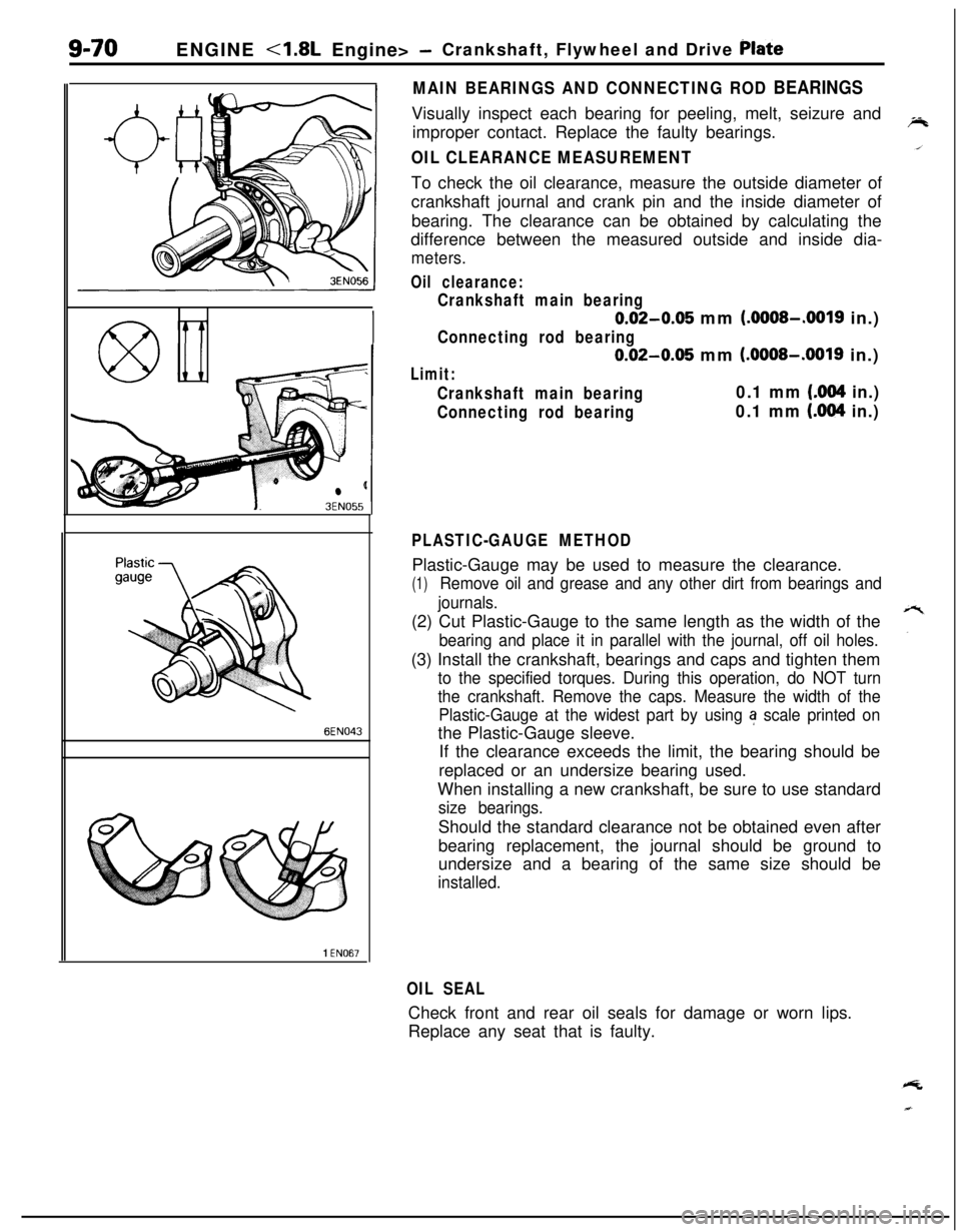
OIL CLEARANCE MEASUREMENTTo check the oil clearance, measure the outside diameter of
crankshaft journal and crank pin and the inside diameter of
bearing. The clearance can be obtained by calculating the
difference between the measured outside and inside dia-
meters.
Oil clearance:
Crankshaft main bearing
0.02-0.05 mm (.OOOS-.0019 in.)
Connecting rod bearing
0.02-0.05 mm (.OOOS-.0019 in.)
Limit:
Crankshaft main bearing0.1 mm (.004 in.)
Connecting rod bearing0.1 mm (.004 in.)
PLASTIC-GAUGE METHODPlastic-Gauge may be used to measure the clearance.
(1)Remove oil and grease and any other dirt from bearings and
journals.(2) Cut Plastic-Gauge to the same length as the width of the
bearing and place it in parallel with the journal, off oil holes.(3) Install the crankshaft, bearings and caps and tighten them
to the specified torques. During this operation, do NOT turn
the crankshaft. Remove the caps. Measure the width of the
Plastic-Gauge at the widest part by using
a scale printed onthe Plastic-Gauge sleeve.
If the clearance exceeds the limit, the bearing should be
replaced or an undersize bearing used.
When installing a new crankshaft, be sure to use standard
size bearings.Should the standard clearance not be obtained even after
bearing replacement, the journal should be ground to
undersize and a bearing of the same size should be
installed.
OIL SEALCheck front and rear oil seals for damage or worn lips.
Replace any seat that is faulty.
Page 410 of 1216
9-126ENGINE <2.0L DOHC Engine>- Front Case, Oil Pump and Silent Shaft
6EN0213
w Crank pulley side
Oil pan
from lower side
‘- Apply sealant7LUOOO0
6LUOO49 tBracket side
-----Be
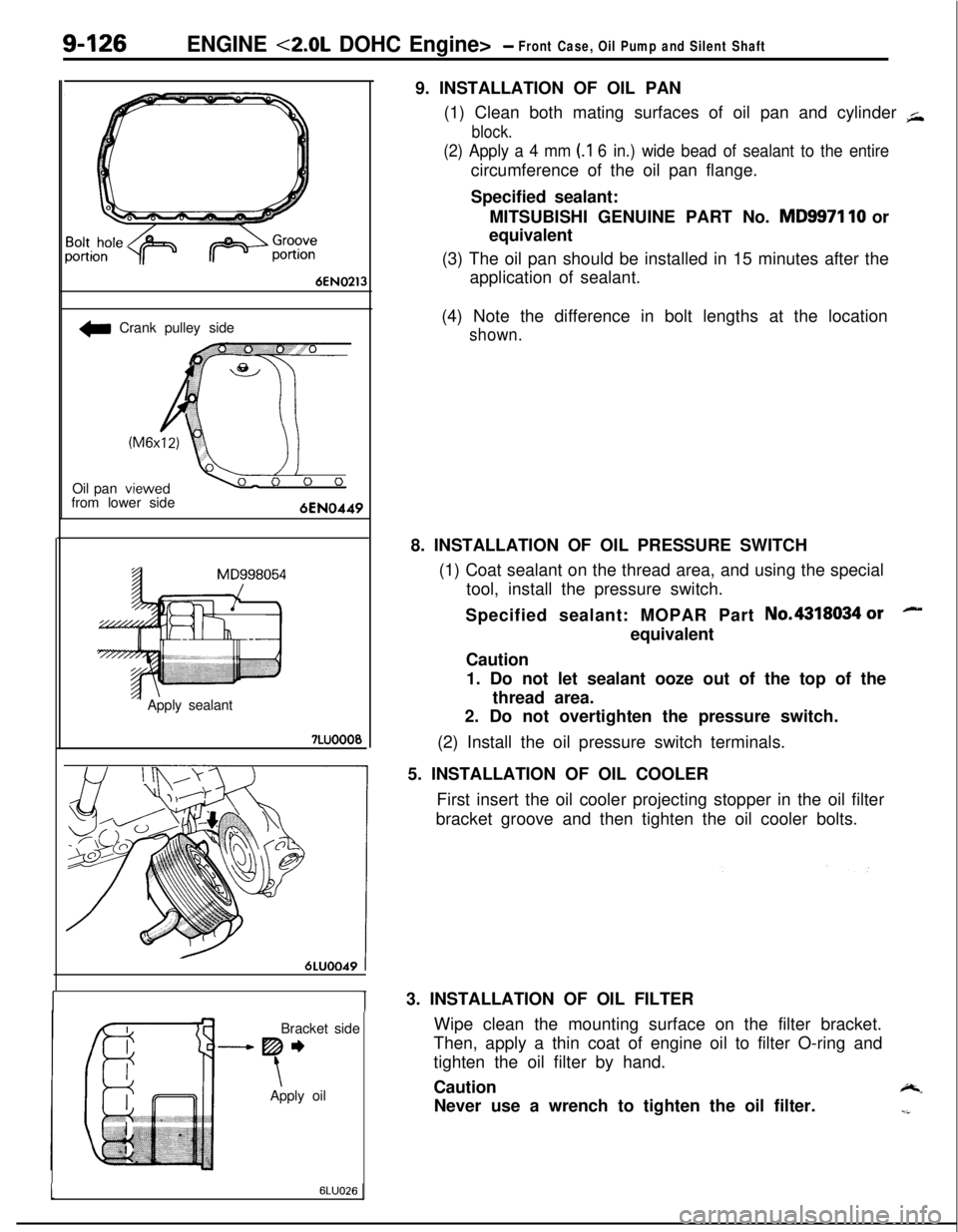
\Apply oil9. INSTALLATION OF OIL PAN
(1) Clean both mating surfaces of oil pan and cylinder
+
block.
(2) Apply a 4 mm (.I 6 in.) wide bead of sealant to the entirecircumference of the oil pan flange.
Specified sealant:
MITSUBISHI GENUINE PART No.
MD9971 10 or
equivalent
(3) The oil pan should be installed in 15 minutes after the
application of sealant.
(4) Note the difference in bolt lengths at the location
shown.8. INSTALLATION OF OIL PRESSURE SWITCH
(1) Coat sealant on the thread area, and using the special
tool, install the pressure switch.
Specified sealant: MOPAR Part No.4318034
orequivalent
Caution
1. Do not let sealant ooze out of the top of the
thread area.
2. Do not overtighten the pressure switch.
(2) Install the oil pressure switch terminals.
5. INSTALLATION OF OIL COOLER
First insert the oil cooler projecting stopper in the oil filter
bracket groove and then tighten the oil cooler bolts.lu3. INSTALLATION OF OIL FILTER
Wipe clean the mounting surface on the filter bracket.
Then, apply a thin coat of engine oil to filter O-ring and
tighten the oil filter by hand.
Caution
-.Never use a wrench to tighten the oil filter.
-i
16LUO26
Page 417 of 1216
ENGINE <2.0L DOHC Engine>- Crankshaft, Flywheel and Drive Plate,91133
INSPECTIONNOSUHAD
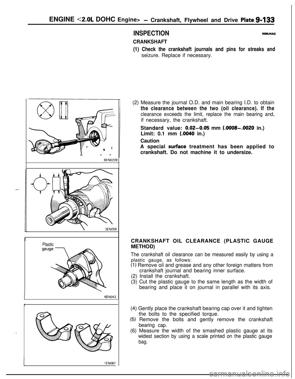
CRANKSHAFT(1) Check the crankshaft journals and pins for streaks and
seizure. Replace if necessary.
6EN0’228
\3EN056
Plastic
6EN043
. .
I1 EN067-(2) Measure the journal O.D. and main bearing I.D. to obtain
the clearance between the two (oil clearance). If the
clearance exceeds the limit, replace the main bearing and,if necessary, the crankshaft.
Standard value:
0.02-0.05 mm (.OOOS-.0020 in.)
Limit: 0.1 mm
(.0040 in.)
Caution
A special
surface treatment has been applied to
crankshaft. Do not machine it to undersize.
CRANKSHAFT OIL CLEARANCE (PLASTIC GAUGE
METHOD)
The crankshaft oil clearance can be measured easily by using aplastic gauge, as follows:
(1) Remove oil and grease and any other foreign matters from
crankshaft journal and bearing inner surface.
(2) Install the crankshaft.
(3) Cut the plastic gauge to the same length as the width of
bearing and place it on journal in parallel with its axis.
(4) Gently place the crankshaft bearing cap over it and tighten
the bolts to the specified torque.
(5) Remove the bolts and gently remove the crankshaft
bearing cap.(6) Measure the width of the smashed plastic gauge at its
widest section by using a scale printed on the plastic gauge
bag.
Page 598 of 1216
16-2PROPELLER SHAFT - Specifications
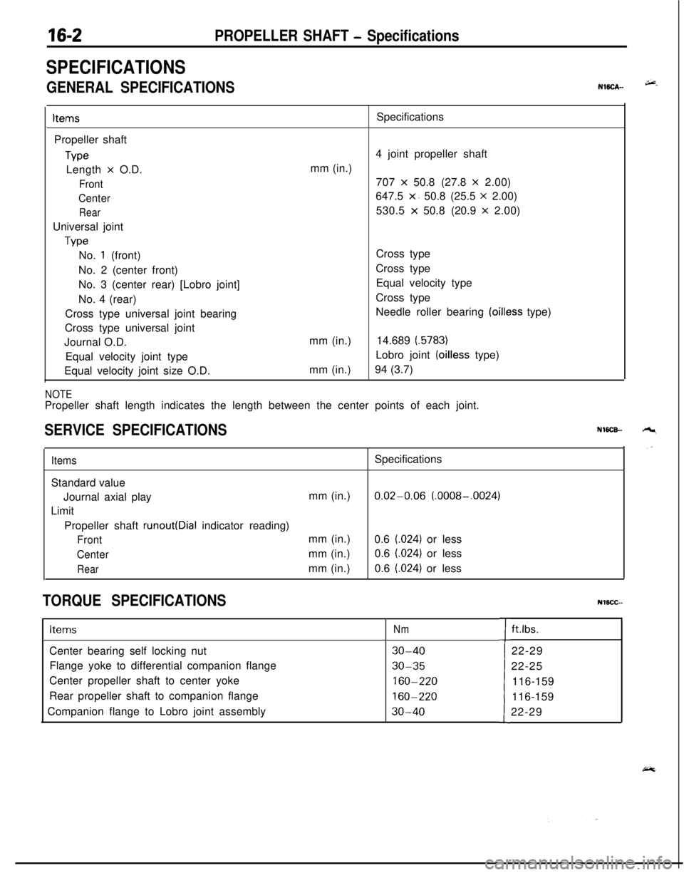
SPECIFICATIONS
GENERAL SPECIFICATIONSNWCA--
ItemsPropeller shaft
TypeLength
x O.D.
Front
Center
RearUniversal joint
TypeSpecifications
4 joint propeller shaft
mm (in.)
707
x 50.8 (27.8 x 2.00)
647.5
x. 50.8 (25.5 x 2.00)
530.5
x 50.8 (20.9 x 2.00)
No.
1 (front)
No. 2 (center front)
No. 3 (center rear) [Lobro joint]
No. 4 (rear)
Cross type universal joint bearing
Cross type universal joint
Journal O.D.
Equal velocity joint type
Equal velocity joint size O.D.mm (in.)
mm (in.)Cross type
Cross type
Equal velocity type
Cross type
Needle roller bearing
(oilless type)
14.689
(.5783)Lobro joint
(oilless type)
94 (3.7)
NOTEPropeller shaft length indicates the length between the center points of each joint.
SERVICE SPECIFICATIONSNWCB-
ItemsSpecifications
Standard value
Journal axial playmm (in.)
0.02-0.06 (.0008-.0024)
Limit
Propeller shaft
runout(Dial indicator reading)
Frontmm (in.)
0.6 (.024) or less
Centermm (in.)0.6 (.024) or less
Rearmm (in.)0.6 (.024) or less
TORQUE SPECIFICATIONSNlBCC--
ItemsNmCenter bearing self locking nut
30-40Flange yoke to differential companion flange
30-35Center propeller shaft to center yoke
160-220Rear propeller shaft to companion flange
160-220Companion flange to Lobro joint assembly
30-40tft.lbs.
22-29
22-25
116-159
116-159
22-29
Page 612 of 1216

17-2REAR SUSPENSION
GENERAL SPECIFICATIONS
LN17CAA
ItemsVehicles with 1.8L EngineVehicles with 2.0L DOHC
Engine
jSuspension system
3-link, torsion axle with coil spring type
Coil spring
Wire dia.
x O.D. x free length
mm (in.) 10.1 x 105.1 x 336.510.2 x 105.2 x 316.5
(40 x 4.14 x 13.25)(40 x 4.14 x 12.46)
[Coil spring identification color]
[Light Blue
x 11[Orange x 11Spring constant
N/mm
(Ibs./in.) 20 (112.0)23 (128.8)
Shock absorber
TypeHydraulic, cylindrical, double-acting type
Max. length
mm (in.) 495 (19.5)485 (19.1)
Min. length
mm (in.) 315 (12.4)315 (12.4)
Strokemm (in.) 180 (7.1)170 (6.7)Damping force [at 0.3 m/set. (0.9
ft./set.)]
ExpansionN (Ibs.)800 (176)
ContractionN (Ibs.)300 (66)
Wheel bearing
TypeUnit ball bearing
SERVICE SPECIFICATIONS
Items
Standard valueToe-in (Left-right difference)
Camber
LimitWheel bearing end play
Rear hub rotary-sliding resistance
Rear hub rotary-sliding torque
NOTEToe-in and camber cannot be adjusted.mm (in.)
mm (in.)
N (Ibs.)
Nm
(ftlbs.)
TORQUE SPECIFICATIONS
Specifications
0+3 (Of.1 18)
-45’
f 30’
0.01 (004) or less
31
(7) or less
1.8
(1.30) or lessNI’ICB-A
ItemsNmft.lbs.
Wheel bearing nut
Shock absorber upper mounting nut
Shock absorber lower mounting nut
Lateral rod mounting nut (body side)
Lateral rod mounting bolt (axle beam side)
Trailing arm mounting bolt
Piston rod tightening nut
Brake hose and tube bracket mounting bolt
Caliper assembly mounting nut
Rear speed sensor mounting bolt
200-260
40-50
80- 100
80-100
100-120
100-120
20-2517-26
50-609-14144-188
29-36
58-72
58-72
72-87
72-87
14-18
12-19
36-43
I7-10
Nl7CGA
Page 626 of 1216

17-16REAR SUSPENSION
SPECIFICATIONS
GENERAL SPECIFICATIONSNl’ICA-B jG
ItemsSpecifications
Suspension systemDouble wishbone suspension type
Coil spring
Wire dia. x O.D.
x free lengthmm (in.)11.0 x 106.0 x 332.5 (.43 x 4.17 x 13.1)Coil spring identification colorPurple
x 1Spring constantN/mm
(Ibs./in.) 25.0 (140)
Shock absorber
TypeHydraulic, cylindrical, double-acting type
Max. lengthmm (in.) 568
(22.4)Min. lengthmm (in.) 380
(15.0)
Strokemm (in.) 188 (7.4)
Damping force [at 0.3 m/set. (0.9
ft./set.)]
ExpansionN (Ibs.) 900 (198)
ContractionN (Ibs.) 300 (66)
SERVICE SPECIFICATIONS
Items
Standard value
Toe-in
CamberSpecificationsmm (in.) 3.6+3 (.14f.l18)
-1"33'f30'
Nl7CEB
:&