Page 376 of 1216
9-92ENGINE <2.0L DOHC Engine> - Cylinder Head Gasket
04A0090
r00
0
697
105
\Front of engine
*Intake side
Exhaust sideSERVICE POINTS OF REMOVAL
NOSJSAP
17. REMOVAL OF RADIATOR UPPER HOSEF-isMake mating marks on the radiator hose and hose clamp,
and then disconnect the radiator hose.
25. DISCONNECTION OF HIGH PRESSURE FUEL HOSE
Caution
Cover the hose connection with rags to prevent splash
of fuel that could be caused by some residual ljressure
in the fuel pipe line.For information concerning the bleeding of the residual
pressure, refer to GROUP 14-Service Adjustment Proce-
dures.
39. REMOVAL OF TIMING BELTRefer to
P.9-98.
47. REMOVAL OF CYLINDER HEAD ASSEMBLYUsing the special tool, loosen the bolts in the order shown
in the figure (in 2 or 3 cycles) and remove. Then remove thecylinder head assembly.A
Page 377 of 1216

ENGINE <2.0L DOHC Engine> - Cylinder Head Gasket9-93
DlADD3fFront of
engine+Exhaust side
OlR0391Cylinder
he/d-Ani-circularpackingSERVICE POINTS OF INSTALLATIONNOSJDDls
48. INSTALLATION OF CYLINDER HEAD GASKET
(1)Use a scraper to clean the gasket surface of the cylinder
block.
Caution
Take care that no foreign material gets into the
cylinder, or into coolant passages or oil passages.(2) Make sure that the gasket has the proper identification
mark for the engine.
(3) Lay the cylinder head gasket on the cylinder block with
the identification mark at the front top.
47. INSTALLATION OF CYLINDER HEAD ASSEMBLY
(1)Use a scraper to clean the gasket surface of the cylinderhead assembly.
Caution
Take care that no foreign material gets into the
coolant passages or oil passages.(2) Using the special tool and a torque wrench, tighten the
bolts to the specified torque in the order shown in the
figure. (in two or three cycles)
Caution
Install the head bolt washers as shown in the
diagram.
41. APPLICATION OF SEALANT TO SEMI-CIRCULAR PACK-
ING
Apply a coating of the specified sealant to the semi-circularpacking and the cylinder head to top surfaces.
Specified sealant: MOPAR Part No.4318034 or equiva-
lent
Page 381 of 1216
--ENGINE
<2.0L DOHC Engine> - Timing Belt9-97
ExhaustIntake cam-
CrankshaftsproketsprockekOlhw51
1r
SERVICE POINTS OF REMOVAL-a3. REMOVAL OF ENGINE MOUNT BRACKET
(1) With a wooden block placed against the oil pan part of
the engine, jack up the vehicle.
CautionJack up gently, so as not to apply a load to the
various parts.
(2) Remove the engine mount bracket,
5. REMOVAL OF DRIVE BELT (ALTERNATOR)
Before removing the drive belt, loosen the water pump
pulley mounting bolts.
21. REMOVAL OF AUTO TENSIONER
(1) Turn the crankshaft clockwise and align the timing
marks so as to bring the No. 1 cylinder to compression
top-dead-centre position.
At this time the timing marks of the camshaft sprocket
and the upper surface of the cylinder head should
coincide, and the dowel pin of the camshaft sprocket
should be at the upper side.
CautionThe crankshaft must always be rotated clockwise.
(2‘) Remove the auto tensioner.
Page 389 of 1216
ENGINE <2.0L DOHC Engine> - Timing Belt9405
I
P(5) Thread the timing belt over the intake side camshaft
sprocket and fix it an indicated position by a clip.
(6) Thread the timing belt over the exhaust side sprocket,
aligning the timing marks with the cylinder head top
surface using two wrenches.
(7) Fix the belt at indicated position by a clip.
(8) Thread the timing belt over the idler pulley, the oil pumpsprocket, the crankshaft sprocket and the tension
pulley in the order shown.
(9) Remove the two clips.
(1O)Lift up the tensioner pulley in the direction of arrow andtighten the center bolt.
(11)Check to see that all timing marks are lined up.
(12)Remove the screwdriver inserted in step (4) and fit the
plug.
(13)Give the crankshaft a quarter counterclockwise turn.
Then, turn it clockwise until the timing marks are lined
up again.
Page 395 of 1216

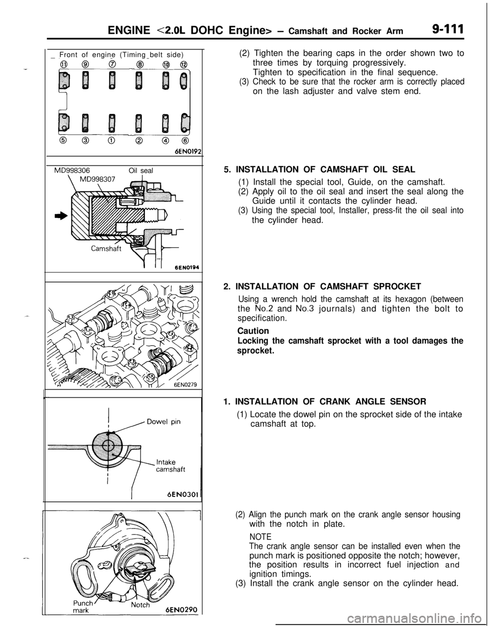
ENGINE <2.0L DOHC Engine> - Camshaft and Rocker Arm9-111_ Front of engine (Timing belt side)
0 Co@
6EN0192
MD998306Oil seal
-
Y-II6ENI01946EN030’
1(2) Tighten the bearing caps in the order shown two to
three times by torquing progressively.
Tighten to specification in the final sequence.
(3) Check to be sure that the rocker arm is correctly placedon the lash adjuster and valve stem end.
5. INSTALLATION OF CAMSHAFT OIL SEAL
(1) Install the special tool, Guide, on the camshaft.
(2) Apply oil to the oil seal and insert the seal along the
Guide until it contacts the cylinder head.
(3) Using the special tool, Installer, press-fit the oil seal intothe cylinder head.
2. INSTALLATION OF CAMSHAFT SPROCKET
Using a wrench hold the camshaft at its hexagon (betweenthe
No.2 and No.3 journals) and tighten the bolt to
specification.Caution
Locking the camshaft sprocket with a tool damages the
sprocket.1. INSTALLATION OF CRANK ANGLE SENSOR
(1) Locate the dowel pin on the sprocket side of the intake
camshaft at top.
(2) Align the punch mark on the crank angle sensor housingwith the notch in plate.
NOTE
The crank angle sensor can be installed even when thepunch mark is positioned opposite the notch; however,
the position results in incorrect fuel injection and
ignition timings.
(3) Install the crank angle sensor on the cylinder head.
Page 396 of 1216
9-112ENGINE <2.0L DOHC Engine> - Cylinder Head and ValveCYLINDER HEAD AND VALVE
DISASSEMBLY ANDREASSEMBLYNewlie6
Disassembly steps
Cylinder head boltWasher
r$!$zr head
Retainer lock
Valve spring retainer
Valve spring
Intake valve
Retainer lock
Valve spring retainer
Valve spring
Exhaust valve
Valve stem seal
Valve spring seat
Valve stem seal
Valve spring seat
Intake valve guide
Exhaust valve guide
Intake valve seat
Exhaust valve seat
.
6E NO196
!??everse the disassembly procedures to reassemble.(2) +e : Refer to “Service Points of Disassembly”.(3) H : Refer to “Service Points of Reassembly”.(4) m : Non-reusable parts
Page 397 of 1216

ENGINE <2.0L DOHC Engine> - Cylinder Head and Valve9-l 13
.
.
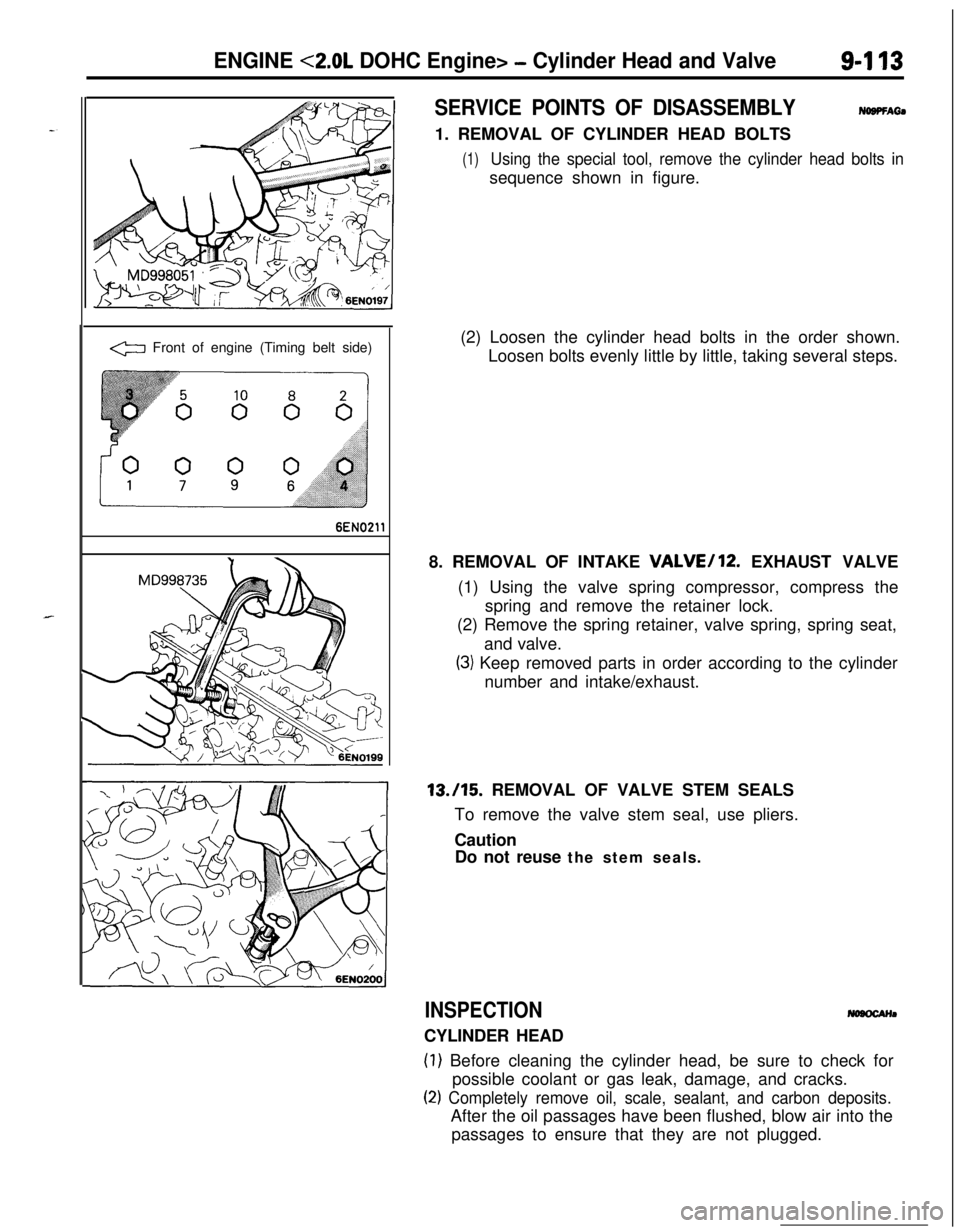
a Front of engine (Timing belt side)
6EN0211
SERVICE POINTS OF DISASSEMBLYNOBPFAti1. REMOVAL OF CYLINDER HEAD BOLTS
(1)Using the special tool, remove the cylinder head bolts insequence shown in figure.
(2) Loosen the cylinder head bolts in the order shown.
Loosen bolts evenly little by little, taking several steps.
8. REMOVAL OF INTAKE
VALVE/12. EXHAUST VALVE
(1) Using the valve spring compressor, compress the
spring and remove the retainer lock.
(2) Remove the spring retainer, valve spring, spring seat,
and valve.
(3) Keep removed parts in order according to the cylinder
number and intake/exhaust.13./15. REMOVAL OF VALVE STEM SEALS
To remove the valve stem seal, use pliers.
Caution
Do not reuse the stem seals.
INSPECTIONCYLINDER HEAD
(1) Before cleaning the cylinder head, be sure to check for
possible coolant or gas leak, damage, and cracks.
(2) Completely remove oil, scale, sealant, and carbon deposits.After the oil passages have been flushed, blow air into the
passages to ensure that they are not plugged.
Page 400 of 1216
9416
I
ENGINE <2.0L DOHC Engine> - Cylinder Head and Valve
I1. INSTALLATION OF CYLINDER HEAD BOLTS
(1) Using the special tool, tighten the cylinder head bolts.
G Front of engine (Timing belt side)(2) Tighten the cylinder head bolts in the sequence shown.
Each bolt should be tightened in two to three steps,
torquing progressively. Tighten to specified torque in
the final sequence.