1991 MITSUBISHI ECLIPSE roof
[x] Cancel search: roofPage 18 of 1216

18INTRODUCTION AND MASTER TROUBLESHOOTING - Precautions b&ire Service
DOING SERVICE WORK IN GROUPS OF VO’bRMORE TECHNICIANS
.-I-7.IIf the service work is to be done by two or more technicians
working together, extra caution must be taken.
VoltagedistributionMaximum
voltage
NOTE ON INSTALLATION OF RADIO EQIJIPMEATeThe computers of the electronic control system has been
designed so that external radio waves will not interfere with
their operation.
However, if antenna or cable of amateur transceiver etc. is
routed near the computers, it may affect the operation of the
computers, even if the output of the transceiver is no more
than
25W.To protect each of the computers from interference by
transmitter (hum, transceiver, etc.), the following should be
observed.1. Install the antenna on the roof or rear bumper.
2.Because radio waves are emitted from the coaxial cable of
the antenna, keep it 200 mm (8 in.) away from the
computers and the wiring harness. If the cable must cross
hthe wiring harness, route it so that it runs at right angles to
the wiring harness.
3.The antenna and the cable should be well matched, and thestanding-wave ratio* should be kept low.
4.A transmitter having a large output should not be installed
in the vehicle.
5.After installation of transmitter, run the engine at idle, emit
radio waves from the transmitter and make sure that the
engine is not affected.
“STANDING-WAVE RATIO
If an antenna and a cable having different impedances are
connected, the input impedance Zi will vary in accordance with
the length of the cable and the frequency of the transmitter,
and the voltage distribution will also vary in accordance with
the location.
The ratio between this maximum voltage and minimum voltage
is called the standing-wave ratio. It can also be represented bythe ratio between the impedances of the antenna and the
cable.The amount of radio waves emitted from the cable increases
as the standing-wave ratio increases, and this increases the
possibility of the electronic components being adversely
affected.
Page 503 of 1216

FUEL SYSTEM - Service Adjustment Procedures <2.0L Engine>14-49
TerminalNo.10screw(2) Disconnect the female connector (for waterproof protec-
tion of the connector) from the connector for ignition timing
adjustment.
(3) Connect the ignition timing adjusting terminal to the groundusing a jumper wire with alligator clips.
(4) Connect terminal No.
10 of the self-diagnosis connector to
the ground with a jumper wire with alligator clips.
(5) Start the engine and run at idle.
(6) Check to be sure that the engine idling speed is the basic
idle speed.
Basic idle speed: 750
250 rpm
If there is a deviation of the engine speed from the basic
idle speed, first determine whether or not the conditions
described below exist, and then use the speed adjustment
screw to adjust to the basic idle speed.
(a) The engine speed may be
20-100 rpm low for a
new vehicle [driven about 500 km (300 miles) or
less], but adjustment is not necessary.
(b) If engine stalling occurs or the engine speed is low
even though the vehicle has been driven about 500
km (300 miles) or more, it is probable that these are
deposits adhered to the throttle valve, so it should
be cleaned.
(Refer to
P.14-51.)(c) If the engine speed is higher than the standard
value even though the speed adjusting screw is
fully close, check for any indication that the idle
position switch (fixed speed adjusting screw) posi-
tion has changed; if there is such an indication,
adjust the idle position switch (fixed speed adjust-
ing screw).
If there is no evidence of a change of position, it is
probable that there is leakage resulting from de-
terioration of the fast-idle air valve (FIAV), so
replace the throttle body.
(7) Turn OFF the ignition switch and stop the engine.
(8) Disconnect the grounding jumper wire from the diagnosis
connector.(9) Disconnect the grounding jumper wire from the ignition
timing connector and mount a waterproof connector.
(1O)Disconnect the tachometer.
(11)Star-t the engine once again and let it idle for about 5
minutes; check to be sure that the idling condition is
normal.
Page 1045 of 1216
23-lBODY
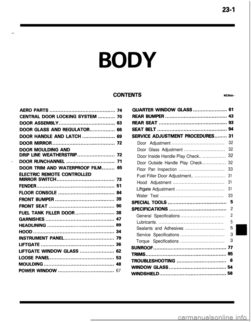
CONTENTSN23Ak-
AERO PARTS..........................................74
CENTRAL DOOR LOCKING SYSTEM...........70
DOOR ASSEMBLY....................................63
DOOR GLASS AND REGULATOR................66
DOORHANDLEANDLATCH.....................69
DOOR MIRROR........................................72
DOOR MOULDING AND
DRIP LINE WEATHERSTRIP........................72
....DOOR RUNCHANNEL...............................71
DOOR TRIM AND WATERPROOF FILM........65
ELECTRIC REMOTE CONTROLLED
MIRROR SWITCH.....................................73
FENDER..................................................51
FLOOR CONSOLE....................................84
FRONT BUMPER......................................39
FRONT SEAT..........................................90
FUEL TANKFILLERDOOR.........................38
GARNISHES............................................47
HEADLINING...........................................89
HOOD....................................................34
INSTRUMENT PANEL................................79
LIFTGATE...............................................36
LIFTGATE WINDOWGLASS......................62
LOOSE PANEL.........................................53
MOULDING.............................................48
POWER WINDOW....................................67
QUARTERWINDOWGLASS......................61
REAR BUMPER........................................43
REAR SEAT............................................93
SEAT BELT.............................................94
SERVICE ADJUSTMENT PROCEDURES........31
Door Adjustment....................................32
Door Glass Adjustment............................32Door Inside Handle Play Check..................
32
Door Outside Handle Play Check................32
Floor PanInspection...............................
33Fuel Filler Door Adjustment.......................
31
Hood Adjustment...................................31
Liftgate Adjustment.................................31
Water Test...........................................33
SPECIAL TOOLS......................................5
SPECIFICATIONS.....................................2
General Specifications..............................
2
Lubricants.............................................5
Sealants and Adhesives...........................5
Service Specifications..............................3
Torque Specifications..............................3
SUNROOF...............................................77TRIMS
....................................................85
TROUBLESHOOTING................................6WINDOW
GLASS.....................................54
WINDSHIELD...........................................58
Page 1049 of 1216
BODY - Specifications/Special Tools23-5
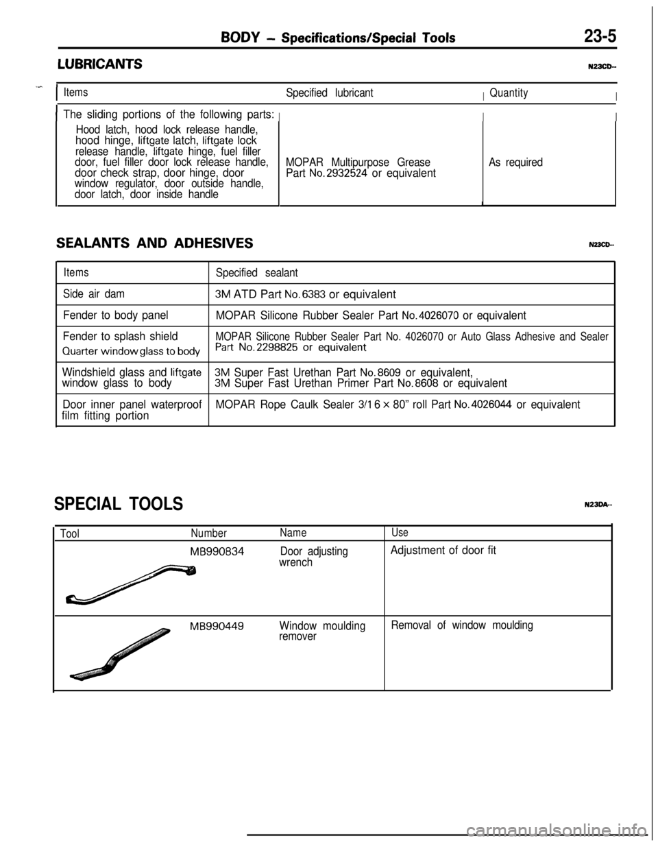
LUBRICANTSNZXD-
.^
IItemsSpecified lubricantIQuantityI
IThe sliding portions of the following parts:III
Hood latch, hood lock release handle,
hood hinge, liftgate latch, liftgate lock
release handle, liftgate hinge, fuel filler
door, fuel filler door lock release handle,
door check strap, door hinge, doorwindow regulator, door outside handle,
door latch, door inside handle
SEALANTS AND ADHESIVES
MOPAR Multipurpose Grease
Part No.2932524 or equivalent
As required
ItemsSpecified sealant
Side air dam
3M ATD Part No.6383 or equivalent
Fender to body panel
MOPAR Silicone Rubber Sealer Part No.4026070 or equivalent
Fender to splash shield
MOPAR Silicone Rubber Sealer Part No. 4026070 or Auto Glass Adhesive and Sealer
Quarter window glass to bodyh-t No.2298825 Or equivalent
Windshield glass and liftgate3M Super Fast Urethan Part No.8609 or equivalent,
window glass to body3M Super Fast Urethan Primer Part No.8608 or equivalent
Door inner panel waterproofMOPAR Rope Caulk Sealer
3/l 6 x 80” roll Part No.4026044 or equivalent
film fitting portion
SPECIAL TOOLS
ToolNumber
MB990834
Name
Door adjusting
wrench
Use
Adjustment of door fit
MB990449Window moulding
removerRemoval of window moulding
Page 1050 of 1216
BODY - Troubleshooting
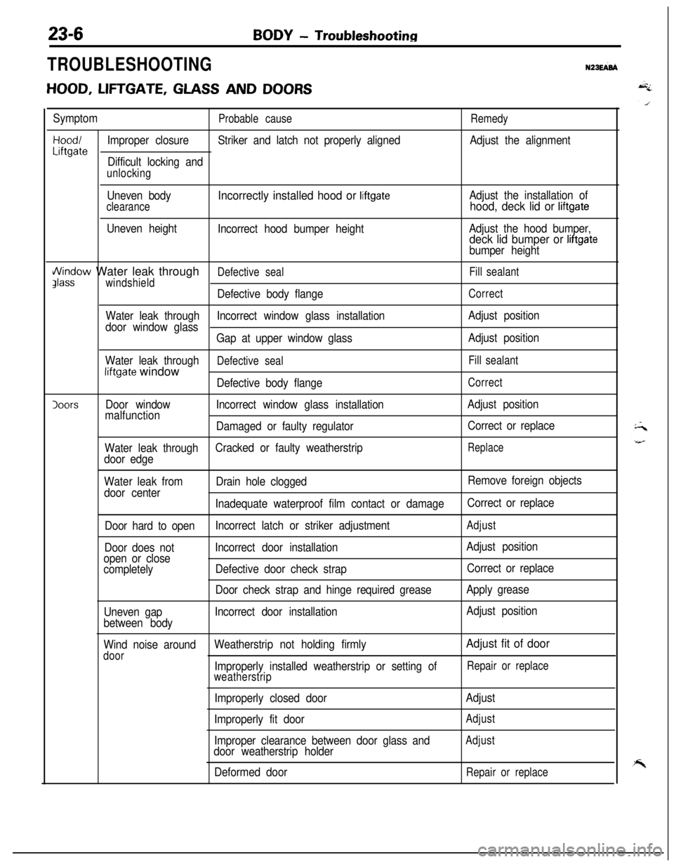
TROUBLESHOOTINGN23EFd
HOOD, LIFTGATE, GLASS AND DOORS
SymptomProbable causeRemedy
Hood/Improper closureStriker and latch not properly alignedAdjust the alignmentLiftgateDifficult locking and
unlocking
Uneven body
clearance
Uneven height
Incorrectly installed hood or liftgate
Incorrect hood bumper heightAdjust the installation of
hood, deck lid or liftgate
Adjust the hood bumper,deck lid bumper or liftgate
bumper height
i/\/indow Water leak throughDefective sealFill sealantJlasswindshield
Defective body flangeCorrect
Water leak throughIncorrect window glass installationAdjust position
door window glass
Gap at upper window glassAdjust position
Water leak through
Defective sealFill sealantliftgate window
Defective body flangeCorrect
IoorsDoor windowIncorrect window glass installationAdjust position
malfunction
Damaged or faulty regulatorCorrect or replace
Water leak throughCracked or faulty weatherstrip
Replace
door edge
Water leak fromDrain hole cloggedRemove foreign objects
door center
Inadequate waterproof film contact or damageCorrect or replace
Door hard to openIncorrect latch or striker adjustment
Adjust
Door does notIncorrect door installationAdjust position
open or close
completelyDefective door check strapCorrect or replace
Door check strap and hinge required greaseApply grease
Uneven gapIncorrect door installationAdjust position
between body
Wind noise aroundWeatherstrip not holding firmly
Adjust fit of door
doorImproperly installed weatherstrip or setting ofRepair or replace
weatherstrip
Improperly closed door
Improperly fit door
Improper clearance between door glass and
door weatherstrip holder
Deformed doorAdjust
Adjust
Adjust
Repair or replace
Page 1051 of 1216

BODY - Troubleshootina23-7
SUNROOF
Symptom
Water leaksProbable causeDust accumulated in drainage of
housing assembly
Clogged drain hose
Remedy
Keep off dust from inside of drain
hose
Blow air into drain hose to remove
dust
Broken or dislocated drain hose,
failed or cracked clip
Worm roof lid weatherstrip
Excessive roof lid-to-body clearance
and improperly fitted weatherstripCheck hose installation and flange
contact
Replace
Adjust
Wind noise
Loose or deformed deflectorRetighten or replace
Page 1076 of 1216
23-32BODY - Service Adjustment Procedures
‘C16A0711
18AO38t
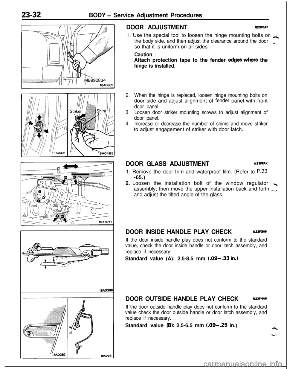
DOOR ADJUSTMENTNZBFEAF1. Use the special tool to loosen the hinge mounting bolts on
Lc
the body side, and then adjust the clearance around the door_so that it is uniform on all sides.
CautionAttach protection tape to the fender
edges where the
hinge is installed.
2.When the hinge is replaced, loosen hinge mounting bolts ondoor side and adjust alignment of
fen,der panel with front
door panel.
3.Loosen door striker mounting screws to adjust alignment of
door panel.
4.Increase or decrease the number of shims and move strikerto adjust engagement of striker with door latch.
DOOR GLASS ADJUSTMENTNZSFFAK1. Remove the door trim and waterproof film. (Refer to
P.23-65.)
2. Loosen the installation bolt of the window regulator
,%assembly; then move the upper installation back and forth
-and adjust the tilted angle of the glass.
DOOR INSIDE HANDLE PLAY CHECKN23FQAH
If the door inside handle play does not conform to the standard
value, check the door inside handle or door latch assembly, and
replace if necessary.Standard value (A): 2.5-8.5 mm
(.09-.33 in.)
DOOR OUTSIDE HANDLE PLAY CHECKN23FHAH
If the door outside handle play does not conform to the standard
value check the door outside handle or door latch assembly, and
replace if necessary.Standard value
(B): 2.5-6.5 mm (.09-.25 in.)4
Page 1077 of 1216
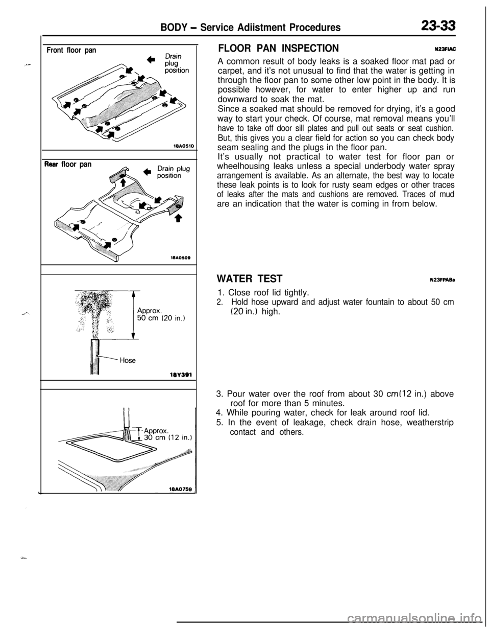
BODY - Service Adiistment Procedures23-33
Front floor pan18AO510
?ear floor pan
lOA
lW391
FLOOR PAN INSPECTIONN23FlACA common result of body leaks is a soaked floor mat pad or
carpet, and it’s not unusual to find that the water is getting in
through the floor pan to some other low point in the body. It is
possible however, for water to enter higher up and run
downward to soak the mat.
Since a soaked mat should be removed for drying, it’s a good
way to start your check. Of course, mat removal means you’ll
have to take off door sill plates and pull out seats or seat cushion.
But, this gives you a clear field for action so you can check bodyseam sealing and the plugs in the floor pan.
It’s usually not practical to water test for floor pan or
wheelhousing leaks unless a special underbody water spray
arrangement is available. As an alternate, the best way to locate
these leak points is to look for rusty seam edges or other traces
of leaks after the mats and cushions are removed. Traces of mudare an indication that the water is coming in from below.
WATER TESTN23FPABs1. Close roof lid tightly.
2.Hold hose upward and adjust water fountain to about 50 cm
(20 in.) high.
3. Pour water over the roof from about 30
cm (12 in.) above
roof for more than 5 minutes.
4. While pouring water, check for leak around roof lid.
5. In the event of leakage, check drain hose, weatherstrip
contact and others.