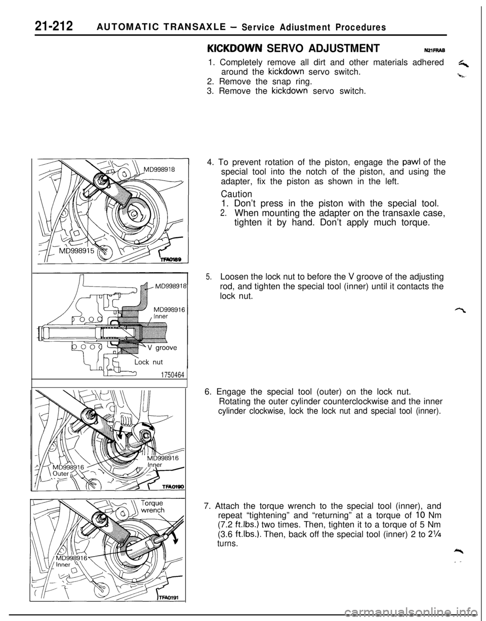
Page 674 of 1216

19-26STEERING - Manual Steering Gear Box
Grease
13AO172(2) Apply specified sealant to the threaded portion of the
top plug.
Specified sealant:
3M ATD, Part No. 8663 or equiva-klent
13. lr
:
ISTALLATION OF RACK SUPPORT/l2. RACK SUPPORT‘RING/II. CUSHION RUBBER/IO. RACK SUPPORT
3VER
(I) Apply a coating of multipurpose grease to the surface of
the rack support that contacts the rack, and then installthe rack support to the rack housing.
Grease: MOPAR Multi-mileage Lubricant Part
No. 2525035 or equivalent
(2) Fill the inner side of the rack support spring with
multipurpose grease, and then install the rack support
spring to the rack housing.
Grease: MOPAR Multi-mileage Lubricant Part
No. 2525035 or equivalent
(3) Install the rubber cushion to the rack support cover.
(4) Apply a coating of the specified sealant to the threaded
-Lpart of the rack support cover, and then install the rack
.‘.support cover to the rack housing.
Specified sealant:3M ATD, Part No.8663 or equiva-lent0 ADJUSTMENT OF TOTAL PINION TORQUE
(1
(2
) Position rack at its center and tighten rack support coverto 15 Nm (1.5 kgm, 11
ftlbs.).
:) In neutral position, rotate pinion shaft clockwise one
turn/4-6 seconds with special tool. Return rack support
cover
30”-60” and adjust torque to the standard value.
Standard value:
From
0-90°From
90°-650°
Caution
0.6-I .3 Nm (5-l 1 inIbs.
0.2-1.0 Nm (2-9 in.lbs.1
I. When adjusting, set the standard value at its
highest value.2. Assure no ratcheting or catching when operating
rack towards the shaft direction.
NOTEWhen it cannot be adjusted within the specified return
angle, check rack support cover components or replace.A
(3) After adjusting, lock rack support cover with locking nut.
Page 680 of 1216
STEERING - Power Steering Gear Box
13A0284
cket
13AO285
13R0551
13R0541
18. REMOVAL OF OIL SEAL
Using a plastic hammer, gently tap the pinion to remove it.21. REMOVAL OF BALL
BEARING/22. OIL SEAL
Using a socket, remove the oil seal and the ball bearing from
the valve housing simultaneously.23. REMOVAL OF
CIRCLIP
(1) Turn the rack stopper clockwise until the end of the
circlip comes out of the slot in the rack housing.
(2) Turn the rack stopper anticlockwise to remove the circlip.26.REMOVAL OF RACK
Pull out the rack slowly.
At this time also take out the rack stopper and the rack
bushing simultaneously.28.REMOVAL OF OIL SEAL
Partially bend oil seal and remove from rack bushing.
CautionDo not damage oil seal press
ftiing surface.
Page 683 of 1216

STEERING - Power Steering Gear BoxOil sealMB991213
Back-up washer
13G014;
Rack bushing
7
136014813K687Seal rings
13A0110-
(2) Cover rack serrations with special tool.
(3) Apply specified fluid on special tool.
Specified fluid:MOPAR ATF PLUS (Automatic Trans-
mission Fluid Type 7176)/Automatic
transmission
fiiid “DEXPON” or
“DEXRON II”
(4) Match oil seal center with rack to prevent reta’iner spring
from slipping and slowly insert rack from power cylinder
side.25. INSTALLATION OF RACK BUSHING ASSEMBLY
Wrap the rack end with vinyl tape, apply a coating of the
specified fluid, and then install the rack bushing and rack
stopper.
Specified fluid:MOPAR ATF PLUS (Automatic Transmis-sion Fluid Type 7176)/Automatic trans-
mission fluid “DEXRON” or “DWRON II”
CautionDo not allow oil seal retainer spring to slip out.
23. INSTALLATION OF
CIRCLIP
Insert circlip to rack stopper hole through cylinder hole. Turnrack stopper clockwise and insert
circlip firmly.
Caution
Insert cirdip to rack stopper hole while turning rack
stopper clockwise.22.lNSTALLATlON OF OIL SEAL
Apply a coating of the specified fluid to the outside of the
oil seal. Press the oil seal into the
valve’housing.
Specified fluid:MOPAR ATF PLUS (Automatic Transmis-sion Fluid Type
7176VAutomatic trans-
mission fluid “DEXRON” or “DEXRON II”
21. INSTALLATION OF BALL BEARINGApply a coating of the specified fluid to the outside of the
ball bearing. Press the ball bearing into the valve housing.
Specified fluid: MOPAR ATF PLUS (Automatic Transmis-sion Fluid Type 7176)/Automatic trans-
mission fluid “DEXRON” or “DEXRON II”
20,lNSTALLATlON OF SEAL RING /lg. PINION AND
VALVE ASSEMBLY
(1) When installing seal rings, press firmly into valve groove.
Apply specified fluid.
Specified fluid:MOPAR ATF PLUS (Autombtic Trans-mission Fluid Type
7176)/+tomatictransmission fluid “DEXRON” or
“DEXRON II”
Page 685 of 1216

STEERING - Power Steering Gear Box
13A017EI
\Silicon grease
Lip
Sealant131564-r-MB990776-A
13A0259l ADJUSTMENT OF TOTAL PINION TORQUE
(1) Position rack at its center. With special tool, tighten racksupport cover to 15 Nm (11
ftlbs.).(2) In neutral position, rotate pinion shaft clockwise one
turn/4-6 seconds with special tool. Return rack, support
cover
30°-60° and adjust torque to the stanoard,vaiue.Standard value:
0.6-l .3 Nm (5-l 1 in.lbs.1
Caution1. When adjusting, set the standard value at its
highest value.2. Assure no ratcheting or catching when operating
rack towards the shaft direction.
NOTEWhen it cannot be adjusted within the specified return
angle, check rack support cover components or replace.
(3) After adjusting, lock rack support cover with locking nut.8. INSTALLATION OF TIE ROD
After installing tie rod to rack, fold tab washe;, end (2
locations) to tie rod notch.
‘*,t, \
\6. APPLICATION OF GREASE TO BELLOWS
Pack tie rod bellows lock groove with specified grease.
Specified grease: Silicone grease3. INSTALLATION OF DUST COVER
(1) Pack dust cover interior and lip with multipurpose grease.Grease: MOPAR Multi-mileage Lubricant Part
No. 2525035 or equivalent
(2) Apply specified sealant to dust cover.
Specified sealant: 3M ATD Part
No.8663 or equiva-
lent
(3) Using the spcial tool, press dust cover to tie rod end.
Page 906 of 1216

21-212AUTOMATIC TRANSAXLE -Service Adiustment Procedures
1750464
KICKOOWN SERVO ADJUSTMENTNZlFRAB1. Completely remove all dirt and other materials adhered
G+around the kickdown servo switch.
-i-s-2. Remove the snap ring.
3. Remove the kickdown servo switch.
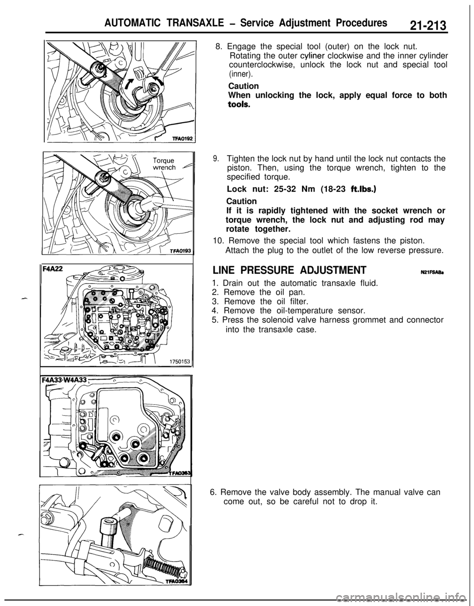
4. To prevent rotation of the piston, engage the
pawl of the
special tool into the notch of the piston, and using the
adapter, fix the piston as shown in the left.
Caution1. Don’t press in the piston with the special tool.
2.When mounting the adapter on the transaxle case,
tighten it by hand. Don’t apply much torque.
5.Loosen the lock nut to before the V groove of the adjusting
rod, and tighten the special tool (inner) until it contacts the
lock nut.
6. Engage the special tool (outer) on the lock nut.
Rotating the outer cylinder counterclockwise and the inner
cylinder clockwise, lock the lock nut and special tool (inner).7. Attach the torque wrench to the special tool (inner), and
repeat “tightening” and “returning” at a torque of
IO Nm
(7.2
ft.lbs.) two times. Then, tighten it to a torque of 5 Nm
(3.6
ftlbs.). Then, back off the special tool (inner) 2 to 2%
turns.*
. .
Page 907 of 1216

AUTOMATIC TRANSAXLE - Service Adjustment Procedures21-2138. Engage the special tool (outer) on the lock nut.
Rotating the outer cyliner clockwise and the inner cylinder
counterclockwise, unlock the lock nut and special tool
(inner).Caution
When unlocking the lock, apply equal force to bothtools.
9.Tighten the lock nut by hand until the lock nut contacts the
piston. Then, using the torque wrench, tighten to the
specified torque.
Lock nut: 25-32 Nm (18-23 ft.lbs.)
Caution
If it is rapidly tightened with the socket wrench or
torque wrench, the lock nut and adjusting rod may
rotate together.
10. Remove the special tool which fastens the piston.
Attach the plug to the outlet of the low reverse pressure.
LINE PRESSURE ADJUSTMENTN2lFSABl
1. Drain out the automatic transaxle fluid.
2. Remove the oil pan.
3. Remove the oil filter.
4. Remove the oil-temperature sensor.
5. Press the solenoid valve harness grommet and connector
into the transaxle case.
6. Remove the valve body assembly. The manual valve can
come out, so be careful not to drop it.
Page 908 of 1216

21-214AUTOMATIC TRANSAXLE - Service Adjustment Procedures
'50157
F4
1
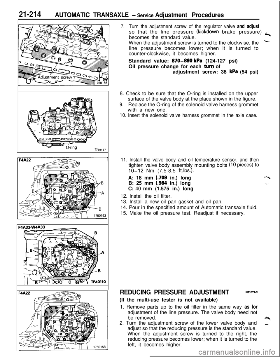
7.Turn the adjustment screw of the regulator valve and adjustso that the line pressure
(kickdown brake pressure) a,becomes the standard value.
When the adjustment screw is turned to the clockwise, the
Lline pressure becomes lower; when it is turned to
counter-clockwise, it becomes higher.
Standard value:
870-890 kPa (124-127 psi)
Oil pressure change for each turq of
adjustment screw: 38
kPa (54 psi)
8. Check to be sure that the O-ring is installed on the upper
surface of the valve body at the place shown in the figure.
9.Replace the O-ring of the solenoid valve harness grommet
with a new one.
10. Insert the solenoid valve harness grommet in the axle case.
11. Install the valve body and oil temperature sensor, and then
(IO pieces) to
tighten valve body assembly mounting bolts
IO-12 Nm (7.5-8.5 ft.lbs.).A: 18 mm
(.709 in.) long
B: 25 mm
(.984 in.) long
C: 40 mm (1.575 in.) long
12. Install the oil filter.
13. Install a new oil pan gasket and oil pan.
14. Pour in the specified amount of Automatic transaxle fluid.
15. Make the oil pressure test. Readjust if necessary.
+-t
--,,
REDUCING PRESSURE ADJUSTMENTNZlFTAC(If the multi-use tester is not available)
1. Remove parts up to the oil filter in the same way as for
adjustment of the line pressure. The valve body need not
be removed.
+%2. Turn the adjustment screw of the lower valve body and_adjust so that the reducing pressure is the standard value.
When the adjustment screw is turned to the right, the
reducing pressure becomes lower; when it is turned to the
left, it becomes higher.
Page 1046 of 1216

23-2
SPECIFICATIONS
GENERAL SPECIFICATIONS
BODY - Specifications
N23CA--
Items
Hood
We
Door
Construction
Regulator system
Locking system
Liftgate
We
Slass installation method
Windshield glass
Quarter window glass
Liftgate window glass
Zlass thicknessmm (in.)
Windshield glass
Liftgate window glass
Door glass
Quarter window glass
‘ower window motor
Type
Revolutions under no loadwm
Revolutions under load
wmAt 1
Nm t.72 ft.lbs.1At 2
Nm (1.45 ft.lbs.1Bound current A
Direction of rotation
‘ower window main switch
Type
Rated load currentA
Lock switch
Power window switch
‘ower window sub switch
TvwRated load current A
‘ower window relay
Maximum contact currentA
Rated coil currentA
Voltage drop between terminalsV(At 12 V and the rated load current)
Specifications
Rear hinged, front opening type
Front-hinged, sash construction
Wire type
Pin-fork type
Inner-hinged, with gas damper
Adhesive type
Adhesive type
Adhesive type5.3
i.21)3.5
t.1413.5
t.1413.5
t.141
Permanent magnet type (Built-in circuit breaker)
75 or more65-95
50-80
34 or less
Clockwise and counter-clockwise
Automatic reset type
10
10
Automatic reset type
10
20
Max. 0.2
0.2 or less