1991 MITSUBISHI ECLIPSE clock
[x] Cancel search: clockPage 331 of 1216

ENGINE <1.8L Engine> - Timing Belt9-47
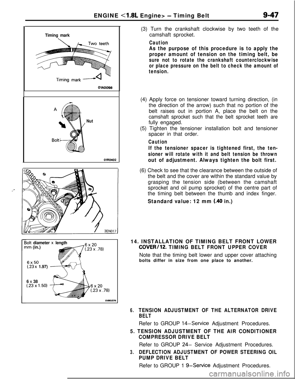
Timing mark
Nut
;olt diameter x lengthim (in.)
6x50(.23 x 1.97)
6
x 38(.23 x 1.50)(3) Turn the crankshaft clockwise by two teeth of the
camshaft sprocket.
Caution
As the purpose of this procedure is to apply the
proper amount of tension on the timing belt, be
sure not to rotate the crankshaft counterclockwise
or place pressure on the belt to check the amount of
tension.(4) Apply force on tensioner toward turning direction, (in
the direction of the arrow) such that no portion of the
belt raises out in portion A, place the belt on the
camshaft sprocket such that the belt sprocket teeth arefully engaged.
(5) Tighten the tensioner installation bolt and tensioner
spacer in that order.
Caution
If the tensioner spacer is tightened first, the ten-
sioner will rotate with it and belt tension be thrown
out of adjustment. Always tighten the bolt first.(6) Check to see that the clearance between the outside of
the belt and the cover are within the standard value by
grasping the tension side (between the camshaft
sprocket and oil pump sprocket) of the centre part of
the timing belt between the thumb and index finger.
Standard value: 12 mm (.40 in.)
14. INSTALLATION OF TIMING BELT FRONT LOWER
COVER/12. TIMING BELT FRONT UPPER COVERNote that the timing belt lower and upper cover attaching
bolts differ in size from one place to another.
6.TENSION ADJUSTMENT OF THE ALTERNATOR DRIVE
BELTRefer to GROUP
14-Service Adjustment Procedures.
5. TENSION ADJUSTMENT OF THE AIR CONDITIONER
COMPRESSOR DRIVE BELTRefer to GROUP
24- Service Adjustment Procedures.
3.DEFLECTION ADJUSTMENT OF POWER STEERING OIL
PUMP DRIVE BELTRefer to GROUP 1
g-Service Adjustment Procedures.
Page 381 of 1216

--ENGINE
<2.0L DOHC Engine> - Timing Belt9-97
ExhaustIntake cam-
CrankshaftsproketsprockekOlhw51
1r
SERVICE POINTS OF REMOVAL-a3. REMOVAL OF ENGINE MOUNT BRACKET
(1) With a wooden block placed against the oil pan part of
the engine, jack up the vehicle.
CautionJack up gently, so as not to apply a load to the
various parts.
(2) Remove the engine mount bracket,
5. REMOVAL OF DRIVE BELT (ALTERNATOR)
Before removing the drive belt, loosen the water pump
pulley mounting bolts.
21. REMOVAL OF AUTO TENSIONER
(1) Turn the crankshaft clockwise and align the timing
marks so as to bring the No. 1 cylinder to compression
top-dead-centre position.
At this time the timing marks of the camshaft sprocket
and the upper surface of the cylinder head should
coincide, and the dowel pin of the camshaft sprocket
should be at the upper side.
CautionThe crankshaft must always be rotated clockwise.
(2‘) Remove the auto tensioner.
Page 388 of 1216

ENGINE <2.0L DOHC Engine> - Timing BeltDowelCamshaft sprocket
Timing mark
6EN0264
Tim
mar22. INSTALLATION OF TIMING BELT
(1) Turn the two sprockets so that their dowel
pind arti
located on top. Then, align the timing marks facing each
-
*other with the top surface of the cylinder head. When,
you let go of the exhaust camshaft sprocket, it will
rotate one tooth in the counterclockwise direction. This
should be taken into account when installing the timing
belt on the sprockets.
NOTE
The same camshaft sprocket is used for the intake andexhaust camshafts and is provided with two timing
marks. When the sprocket is mounted on the exhaust
camshaft, use the timing mark on the right with the
*dowel pin hole on top. For the intake camshaft
-sprocket, use the one on the left with the dowel pin
hole on top.
(2) Align the crankshaft sprocket timing mark.
(3) Align the oil pump sprocket timing mark.
(4) Remove the plug on the cylinder block and insert a
Phillips screwdriver [shank diameter 8 mm
(.31 in.)]
through the hole.
If it can be inserted as deep as 60 mm (2.4 in.) or more,the timing marks are correctly aligned. If the inserted
depth is only
20-25 mm (.8-l .O in.), turn the oil pump
sprocket one turn and realign timing marks. Then checkto ensure that the screwdriver can be inserted 60 mm
(2.4 in.) or more. Keep the screwdriver inserted until theinstallation of the timing belt is finished.,+
.
NOTEStep (4) is performed to ensure that the oil pump
sprocket is correctly positioned with reference to the
silent shafts.
Page 389 of 1216

ENGINE <2.0L DOHC Engine> - Timing Belt9405
I
P(5) Thread the timing belt over the intake side camshaft
sprocket and fix it an indicated position by a clip.
(6) Thread the timing belt over the exhaust side sprocket,
aligning the timing marks with the cylinder head top
surface using two wrenches.
(7) Fix the belt at indicated position by a clip.
(8) Thread the timing belt over the idler pulley, the oil pumpsprocket, the crankshaft sprocket and the tension
pulley in the order shown.
(9) Remove the two clips.
(1O)Lift up the tensioner pulley in the direction of arrow andtighten the center bolt.
(11)Check to see that all timing marks are lined up.
(12)Remove the screwdriver inserted in step (4) and fit the
plug.
(13)Give the crankshaft a quarter counterclockwise turn.
Then, turn it clockwise until the timing marks are lined
up again.
Page 390 of 1216

9-106ENGINE <2.0L DOHC Engine> - Timing Belt. ADJUSTMENT OF TIMING BELT TENSION
(1) After turning the crankshaft
l/4 turn counterclockwise,.5;;turn it clockwise to move the No. 1 cylinder to top dead
center.(2) Loosen the center bolt, and then, as shown in the
illustration, attach the special tool and a torque wrench
and apply a torque of 2.6-2.8 Nm
(1.88-2.03 ft.lbs.).If the body interferes with the special tool and the
torque wrench, use a jack to slightly raise the engine
assembly.
NOTEUse a torque wrench that is capable of measurement
within a range of
O-3 Nm (O-2.2 ft.lbs.).(3) Holding the tensioner pulley with the special tool and
torque wrench, tighten the center bolt to specification.
(4) Screw the special tool into the engine left support
bracket until its end makes contact with the tensioner
arm. At that point, screw the special tool in some more
and then remove the set wire attached to the auto
tensioner.(5) Remove the special tool.
(6) Rotate the crankshaft two complete turns clockwise
and leave it as is for about 15 minutes. Then, measure
the auto tensioner protrusion “A” (distance between
the tensioner arm and auto tensioner body) to ensure,.+
that it is up to specification.
Standard value:
3.8-4.5 mm (.15-.18 in.)
If it is out of specification, repeat steps (6) through (1)
until the specified value is obtained.
(7) If the clearance between the tensioner arm and the
auto tensioner body cannot be measured (when the
engine is being mounted, etc.), the following proce-
dures can be used to substitute for the ordinan/ methodof measurement.
@ Screw in the special tool until it contacts the
tensioner arm.
@ From that point of contact, further screw in the
special tool, screwing it in until the push rod of the
auto tensioner body is caused to move backward
and the tensioner arm contacts the auto tensioner
body.Check to be sure that the amount that the special
tool has been screwed in (when the push rod
moves backward) is the standard value.
Standard value: 2.5-3 turns
Page 497 of 1216

FUEL SYSTEM - Service Adjustment Procedures <1.8L Engine>14-43
(14)lf it is out of specification, adjust by loosing the throttle
position sensor mounting screws and rotating the throttle
position sensor. After adjustment, tighten the screws
firmly.
NOTEClockwise rotation of the throttle position sensor increases
the output voltage.
Throttle position
sensor
t-/ /I
(15)Set the ignition switch at OFF.
(16)Adjust the free play of the accelerator cable.
(17)Reconnect the connectors of the idle speed control servo.
(18)Remove the voltmeter.
(19)Start the engine and check that the engine is running at thecurb idle speed.
Curb idle speed:
700f 100 rpm
(20)Set the ignition switch at OFF, disconnect the negative
battery cable and reconnect it more than
10 seconds later
(By doing so, the memory storing the diagnosis data duringthe idle speed control adjustment is cleared.)
(21)Restart the engine, let it run at idle for about 5 minutes, andcheck that the engine is running in good idle quality.
THROTTLE BODY (THROTTLE VALVE AREA)
CLEANING
NllRCK
(1) Warm up the engine, then stop it.
(2) Remove the air intake hose from the throttle body.
(3) Spray cleaning solvent into the valve through the throttle
body intake port and leave it for about 5 minutes.
(4) Start the engine, race it several times and idle it for about 1minute. If the idling speed becomes unstable slightly open
the throttle valve to keep the engine running.
(5) If the throttle valve deposits are not removed, repeat steps
(3) and (4).
(6) Attach the air intake hose.
(7) Disconnect the battery terminal for
10 seconds or more,
and then reconnect it.
(8) Adjust the idle speed control and throttle position sensor.
Page 504 of 1216

14-50FUEL SYSTEM - Service Adjustment Procedures <2.0L Engine>THROllLE
POSITION SENSOR ADJUSTME!-T’“.
(1) Slacken the accelerator cable enough.
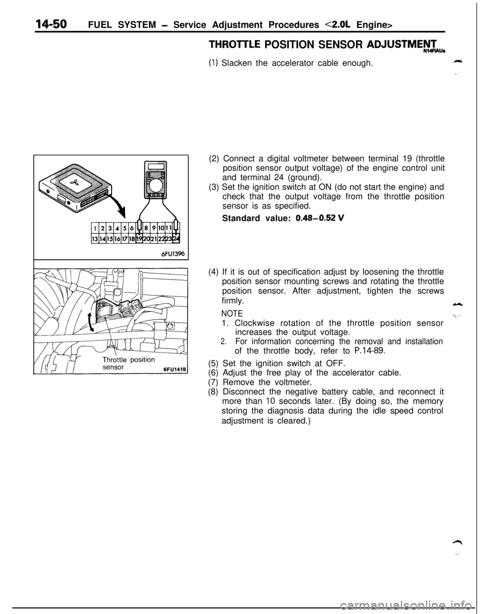
6FU13%(2) Connect a digital voltmeter between terminal 19 (throttle
position sensor output voltage) of the engine control unit
and terminal 24 (ground).
(3) Set the ignition switch at ON (do not start the engine) and
check that the output voltage from the throttle position
sensor is as specified.
Standard value:
0.48-0.52 V(4) If it is out of specification adjust by loosening the throttle
position sensor mounting screws and rotating the throttle
position sensor. After adjustment, tighten the screws
firmly.
NOTE1. Clockwise rotation of the throttle position sensor
increases the output voltage.
2.For information concerning the removal and installationof the throttle body, refer to
P.14-89.(5) Set the ignition switch at OFF.
(6) Adjust the free play of the accelerator cable.
(7) Remove the voltmeter.
(8) Disconnect the negative battery cable, and reconnect it
more than
10 seconds later. (By doing so, the memory
storing the diagnosis data during the idle speed control
adjustment is cleared.)
Page 506 of 1216

14-52FUEL SYSTEM - Service Adjustment Procedures <2.0L Engine>
IDLE POSITION SWITCH ADJUSTMENT
Caution
N14UDAThe idle position switch has been adjusted by the manu-
facturer.Do not, therefore, disturb the setting of the idle-position
switch.
If the setting is disturbed as a result of carelessness, or if
the idle-position switch is replaced, make the necessary
setting as described below.
(1) Sufficiently loosen the tension of the accelerator cable.
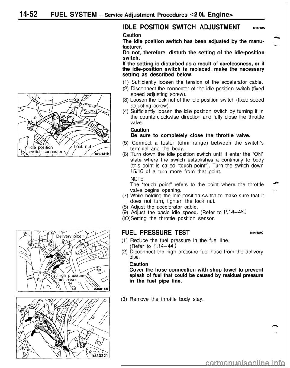
(2) Disconnect the connector of the idle position switch (fixed
speed adjusting screw).
(3) Loosen the lock nut of the idle position switch (fixed speed
adjusting screw).
(4) Sufficiently loosen the idle position switch by turning it in
the counterclockwise direction and fully close the throttle
valve.Caution
Be sure to completely close the throttle valve.
(5) Connect a tester (ohm range) between the switch’s
terminal and the body.
(6) Turn down the idle position switch until it enter the “ON”
state where the switch establishes a continuity to body
(this point is called “touch point”). Turn the switch down
15/16 of a turn more from that point.
NOTEThe “touch point” refers to the point where the throttle
valve begins opening.
(7) While holding the idle position switch to make sure that it
does not turn, tighten the lock nut.
(8) Adjust the accelerator cable.
(9) Adjust the basic idle speed. (Refer to P.14-48.)
(lO)Setting the throttle position sensor.
FUEL PRESSURE TESTN14FNAO(1) Reduce the fuel pressure in the fuel line.
(Refer to
P.14-44.)(2) Disconnect the high pressure fuel hose from the delivery
pipe.Caution
Cover the hose connection with shop towel to prevent
splash of fuel that could be caused by residual pressurein the fuel pipe line.
(3) Remove the throttle body stay.